Table of Contents
Advertisement
Quick Links
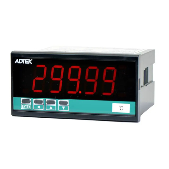
CS2-T
TEMPERATURE Indicator
DESCRIPTION
CS2-T Temperature Indicator has been designed with high accuracy
measurement, display and communication of Thermocouple or
Pt100Ω.
They are also building in 4 Relay outputs, 3 External Control Inputs, 1
Analogue output and 1 RS485 (Modbus RTU Mode) interface with
versatile functions such as control, alarm, re-transmission and
communication for a wide range of machinery and testing equipments
application.
FEATURE
●
Measuring RTD: Pt100Ω; Thermocouple: K, J, E, T, R, S, B
●
4 relay can be programmed individual to be a Hi / Lo / Hi Latch / Lo Latch / Go energized with Start Delay /
Hysteresis / Energized & De-energized Delay functions, or to be a remote control.
●
Analogue output and RS 485 communication port in option
●
3 external control inputs can be programmed individual to be Relative PV (Tare) / PV Hold / Maximum or
Minimum Hold / DI (remote monitoring) / Reset for Relay Energized Latch....
●
CE Approved & RoHS
ORDERING INFORMATION
Input
−
CS2−T−
Signal
CODE
INPUT RANGE
P1
Pt100Ω -50.00~199.99 °C
P2
Pt100Ω -150.0~800.0 °C
TECHNICAL SPECIFICATION
Input
Measuring Range
Input Impedance
P1 Pt100Ω -50.00~199.99 °C
≥ 1M ohm
P2 Pt100Ω -150.0~800.0 °C
≥ 1M ohm
K1 Type K 0.0~1200.0 °C
≥ 1M ohm
≥ 1M ohm
J1 Type J 0.0~750.0 °C
≥ 1M ohm
E1 Type E 0.0~1000.0 °C
T1 Type T 0.0~400.0 °C
≥ 1M ohm
R1 Type R 400~1600 °C
≥ 1M ohm
S1 Type S 400~1600 °C
≥ 1M ohm
≥ 1M ohm
B1 Type B 400~1800 °C
Calibration:
Digital calibration by front key
A/D converter:
16 bits resolution
Pt100Ω: ≤ ±0.1% of FS ± 1C;
Accuracy:
Thermocouple: ≤ ±0.2% of FS ± 1C;
15 cycles/sec
Sampling rate:
Response time:
≤100 m-sec.(when the AvG = "1") in standard
25 ± 10˚C, error ≤ 0.5˚C
Cold junction in T/C:
Display & Functions
Numeric: 5 digits, 0.8"(20.0mm)H red high-brightness LED
LED:
Relay output indication: 4 square red LED
RS 485 communication: 1 square orange LED
E.C.I. function indication: 3 square green LED
Max/Mini Hold indication: 2 square orange LED
Display range:
According to sensor range
Scaling function:
Fix range, please don't set.
Fix range, please don't set.
Decimal point:
Fix range, please don't set.
Over range indication:
ovfl, when input is over 20% of input range Hi
-ovfl, when input is under -20% of input range Lo
Under range indication:
Max / Mini recording:
Maximum and Minimum value storage during power on.
Display functions:
PV / Max(Mini) Hold / RS 485 Programmable
Relative PV / PV Hold / Reset for maxi(mini) hold /
Front key functions:
Reset for relay energized latch programmable
Relay
−
Analogue
−
RS 485
Output
Output
Port
OPTION 1
OPTION 2
OPTION 3
CODE
INPUT RANGE
CODE RELAY O/P
K1
Type K 0.0~1200.0
°C
J1
Type J 0.0~750.0
°C
Type E 0.0~1000.0
E1
°C
T1
Type T 0.0~400.0
°C
R1
T/C type R 400~1600
°C
T/C type S 400~1600
S1
°C
T/C type B 400~1800
B1
°C
Excitation Supply
Sensing Current: 1.6mA
CS2-T-2010-09-27
−
Aux.
Powered
CODE ANALOG O/P
N
None
N
None
R2
2 Relay
0(1) ~ 5 V
V
0 ~ 10 V
R4
4 Relay
0 ~ 10 mA
I
0(4)~20 mA
Low cut:
Digital fine adjust:
Reading Stable Function
Average:
Moving average:
Digital filter:
Set-points:
Control relay:
Relay energized mode: Energized levels compare with set-points:
Banks pre-set:
Energizing functions:
External Control Inputs(ECI)
Input mode:
Functions:
Debouncing time:
CODE RS485 PORT
CODE AXU. POWER
N
None
A
AC115/230V
8
RS 485
OPTION 4
AC 85~264V
ADH
DC 100~300V
ADL
DC 20~56V
Settable range: -19999~29999 counts
pVzro: Settable range: -19999~+29999
pVspn: Settable range: -19999~+29999
Average:
Moving average:
Digital filter:
Four set-points
Four relays
Relay 2 & Relay 3: Dual FORM-C, 5A/230Vac, 10A/115V
Relay 1 & Relay 4: Dual FORM-A, 1A/230Vac, 3A/115V
Hi / Lo / Go.12 / Go.23 / Hi.HLd / Lo.HLd; programmable
DO function: Energized by RS485 command of master.
4 banks pre-set for all relay functions to relative 4
difference scaling, and selectable by 3 External
Control Inputs(E.C.I.) Or front key
Start delay / Energized & De-energized delay / Hysteresis /
Energized Latch
Start band(Minimum level for Energizing): 0~9999counts
Start delay time: 0:00.0~9(Minutes):59.9(Second)
Energized delay time: 0.00.0~9(Minutes):59.9(Second)
De-energized delay time: 0.00.0~9(Minutes):59.9(Second)
Hysteresis: 0~5000 counts
3 ECI points, Contact or open collect input, Level trigger
Relative PV (Tare) / PV Hold / Reset for Max or Mini. Hold /
DI / Reset for Relay Energized latch / 4 Banks selection
Settable range 5 ~255 x (8m seconds)
C2-09
-1/8
Advertisement
Table of Contents

Related Manuals for ADTEK CS2-T


Summary of Contents for ADTEK CS2-T
- Page 1 CS2-T TEMPERATURE Indicator DESCRIPTION CS2-T Temperature Indicator has been designed with high accuracy measurement, display and communication of Thermocouple or Pt100Ω. They are also building in 4 Relay outputs, 3 External Control Inputs, 1 Analogue output and 1 RS485 (Modbus RTU Mode) interface with...
- Page 2 Indication Comm. status R L 1 C OM Terminate Resistor RL 2 CI11 Control Input (at latest unit): 120~300ohm/0.25W status (typical: 150ohm) Display screen Mini. Hold status °C ENT/FN Operation Key 31 32 Engineer Unit RS485 Port C2-09 CS2-T-2010-09-27 -2/8...
- Page 3 Especially, the [pVzro] & [pVspn] are not only in zero & span of PV, but also any lower point for [pVzro] & higher point for [pVspn]. The meter will be linearization for full scale. CS2-T-2010-09-27 C2-09 -3/8...
- Page 4 ► lOhld(Lo & latch). As the meter is power on and no input to display the "0" caused the relay will be energized. User can set a band and delay time to inhibit the energized of relay. C2-09 CS2-T-2010-09-27 -4/8...
- Page 5 ECI is to be closed. (external control inputs) status but also controls the relays output (DO) by Hi(Lo) Energized Latch & Reset RS485 communication ports. CS2-T & SC2-RL APPLICATION MEASURING & RS485 COMMUNICATION Hi Setting [ry_.sp] RS485 wiring 1.2KM maximum...
- Page 6 M.RS(Maximum or Minimum Reset) / relative value as like as ECI2 close. R.RS(Reset for Relay Latch) If the front key function has been set, the terminal input for ECI ● Engineer Label: over 80 types. will be disabling. C2-09 CS2-T-2010-09-27 -6/8...
- Page 7 ZSclr Span delay time E2=dn Adjustment ry!fd function ZSclr Adjustment for yes / none / aOzro / 0.00.0~ PV display aOspn / both 9(M).59.9(S) none / pVzro / pVspn / both Next Page Next Page Next Page CS2-T-2010-09-27 C2-09 -7/8...
- Page 8 / go-@3 ry$hy: Relay 4 Hysteresis ry$hy 0~5000 counts ry$rd: Relay 4 )0)0 energized delay time ry$rd 0.00.0~ 9(M).59.9(S) ry$fd: Relay 4 )0)0 de-energized delay time ry$fd 0.00.0~ 9(M).59.9(S) Plesae refer to operating manual for detail description C2-09 CS2-T-2010-09-27 -8/8...
Need help?
Do you have a question about the CS2-T and is the answer not in the manual?
Questions and answers