Table of Contents
Advertisement
Quick Links
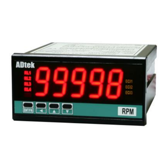
CS2-RL PULSE (FREQ.) Indicator
DESCRIPTION
CS2-RL RPM Indicator has been designed with high accuracy
measurement, display and communication of pulse (Frequency).
The innovation feature is auto-range input from 0.01Hz~ 100KHz
(option ~140KHz) and the display resolution will auto-change to
show the highest according to input frequency.
They are also building in 4 Relay outputs, 3 External Control Inputs, 1
Analogue output and 1 RS485(Modbus RTU Mode) interface with
versatile functions such as control, alarm, re-transmission and
communication for a wide range of testing and machinery control
applications.
FEATURE
●
Measuring Frequency AUTO RANGE 0.01~100KHz / ~140KHz(optional) / Contact, NPN, PNP, Voltage pulse
can be switch on rear of meter
●
Accuracy: ± 0.005%; Display range: 0~99999; Decimal Point auto moving according to input frequency
●
4 relay can be programmed individual to be a Hi / Lo / Hi Latch / Lo Latch / Go energized with Start Delay /
Hysteresis / Energized & De-energized Delay functions, or to be a remote control.
●
Analogue output and RS 485 communication port in option
●
3 external control inputs can be programmed individual to be Tare (Relative PV) / PV Hold / Maximum or
Minimum Hold / DI (remote monitoring) / Reset for Relay Energized Latch....
●
CE Approved & RoHS
ORDERING INFORMATION
CS2−RL−
Input
Input
Mode
level
CODE
C 00
N
P
V
Input mode and level
05
can be changed by
12
dip switches on rear
of meter
24
O xx
U P
TECHNICAL SPECIFICATION
Input
Input Frequency
Input Mode
Mech. Contact
0.01Hz ~ 50 Hz
NPN
0.01Hz ~ 50 Hz
PNP
0.01Hz ~ 100KHz
0.01Hz ~ 140KHz
Voltage Pulse
(optional)
Pick Up Sensor
Input Mode(NPN, PNP, Contact) & Level(5Vp, 12Vp, 24Vp)
changeable by dip switch of rear terminal block.
Calibration:
Doesn't need calibration
Auto range: 0.01Hz ~ 100KHz (~140KHz in option);
Input range:
≤ 0.005% of FS 1C;
Accuracy:
Sampling time:
15 cycles/sec(≥15Hz);
f cycles/sec(≤15Hz)
Response time:
≤100 m-sec(when the AvG = "1")
Time out function:
Auto, Manual programmable, In manual mode, the period
of time out can be set 0.0 sec~999.9sec
Display & Functions
LED:
Numeric: 5 digits, 0.8"(20.0mm)H red high-brightness LED
Relay output indication: 4 square red LED
RS 485 communication: 1 square orange LED
E.C.I. function indication: 3 square green LED
Max/Mini Hold indication: 2 square orange LED
Display type:
RPM / RPS / Linear line speed / Frequency programmable
Display range:
0.0000~99999 with auto moving of decimal point
Resolution of PV:
Decimal point will Auto-changed according to input
(Auto-Moving for d.p.)
Auto / Semi-Auto / Fix; 3 mode programmable
−
Relay
−
Analogue
−
RS 485 Port
Output
Output
OPTION 1
OPTION 2
OPTION 3
INPUT MODE
CODE REALY OUTPUT
Contact
N
None
R2
NPN
2 Relay
R4
PNP
4 Relay
Voltage Pulse
5V pulse
12V pulse
Please specify the range
24V pulse
of amplitude, if the input
Specify
mode has specified to be
Pick Up sensor
pick up sensor.
Input Level
High Level: over 2/3 of input level
Low Level: under 1/3 of input level
Specified by order
CS2-RL-2010-10-15
−
AUX.
−
*Optional
POWER
Function
CODE
ANALOG O/P
CODE
RS 485 PORT
N
None
N
None
8
RS 485
0(1) ~ 5 V
V
0 ~ 10 V
0 ~ 10 mA
I
0(4)~20 mA
Compensate error from 0.001~9.999
Compensation factor:
Over range indication:
ovfl, when input is over 20% of input range Hi
Max / Mini recording:
Maxi & Mini Value of PV storage during power on.
Display functions:
PV / Max(Mini) Hold / RS 485 programmable
Front key functions:
Relative PV / PV Hold / Reset for maxi(mini) hold /
Reset for relay energized latch programmable
Low cut:
Settable range: -19999~29999 counts
pVzro: Settable range: 0~+99999
Digital fine adjust:
pVspn: Settable range: 0~+99999
Reading Stable Function
Average:
Settable range: 1~99 times
Moving average:
Settable range: 1(None)~10 times
Digital filter:
Settable range: 0(None)/1~99 times
Control Functions(option)
Set-points:
Four set-points
Control relay:
Four relays
Relay 2 & Relay 3: Dual FORM-C, 5A/230Vac, 10A/115V
Relay 1 & Relay 4: Dual FORM-A, 1A/230Vac, 3A/115V
Programmable from 0 / 0.0 / 0.00 / 0.000 / 0.0000
D.P. of set point:
Relay energized mode:
Energized levels compare with set-points:
Hi / Lo / Go.12 / Go.23 / Hi.HLd / Lo.HLd; programmable
DO function: Energized by RS485 command of master.
Energizing functions:
Start delay / Energized & De-energized delay / Hysteresis /
Energized Latch
Start band(Minimum level for Energizing): 0~9999counts
Start delay time: 0:00.0~9(Minutes):59.9(Second)
Energized delay time: 0.00.0~9(Minutes):59.9(Second)
De-energized delay time: 0.00.0~9(Minutes):59.9(Second)
Hysteresis: 0~5000 counts
Customize function is welcome. Please contact with our
sales for detail.
CODE AUX. POWER
A
AC115/230V
OPTION 4
AC 85~264V
ADH
DC 100~300V
ADL
DC 20~56V
C2-11
-1/9
Advertisement
Table of Contents

Related Manuals for ADTEK CS2-RL


Summary of Contents for ADTEK CS2-RL
- Page 1 CS2-RL PULSE (FREQ.) Indicator DESCRIPTION CS2-RL RPM Indicator has been designed with high accuracy measurement, display and communication of pulse (Frequency). The innovation feature is auto-range input from 0.01Hz~ 100KHz (option ~140KHz) and the display resolution will auto-change to show the highest according to input frequency.
-
Page 2: Installation
Max. Hold status D-S is on when it is in down site Relay status Indication Comm. status R L 1 C OM RL 2 CI11 Control Input status Display screen Mini. Hold status ENT/FN Operation Key Engineer Unit C2-11 CS2-RL-2010-10-15 -2/9... -
Page 3: Function Description
High point from 180.00 to 170.00 19(99 M axim um Hold 18)00 Present Value 17)00 10)00 8)00 Reset the Max Level 5%00 (M ini) H old by Trigger EC I or F. Key [ l Osc ] INPUT _ 9.00V 2.75V CS2-RL-2010-10-15 C2-11 -3/9... - Page 4 [ rYsb] Start Band Hi / Lo Relay Energized Fig.1 Relay [ry_.sp] Hi Setting Start Delay Time Energized [ r Y s d ] [ry_.sp] Lo Setting [ry_.md] Hi Relay Energized Lo Relay Energized C2-11 CS2-RL-2010-10-15 -4/9...
- Page 5 [ ecI_] can be set to be rYrst(Reset the Relay energized latch). When the PV meets the condition of relay energizing, the relay will be energized and latch until the ECI is to be closed. CS2-RL-2010-10-15 C2-11 -5/9...
- Page 6 Calibrating Input Signal do not process fail (Please check Calibrating Input Signal) Calibrating Input Signal error aoCng (Please process Calibrating Output Signal) Calibrating Output Signal do not process fail (Please check Calibrating Output Signal) Calibrating Output Signal error C2-11 CS2-RL-2010-10-15 -6/9...
- Page 7 M.RS(Maximum or Minimum Reset) / relative value as like as ECI2 close. R.RS(Reset for Relay Latch) If the front key function has been set, the terminal input for ECI ● Engineer Label: over 80 types. will be disabling. CS2-RL-2010-10-15 C2-11 -7/9...
-
Page 8: Operating Diagram
E1=up: ECI.1 set )0)0 Point of energized delay Span Adjust. for to be UP Key set-point time Analogue High ry!rd E1=up function aOspn Output 0~0.0000 0.00.0~ yes / -38011~27524 9(M).59.9(S) Next Page Next Page Next Page Next Page C2-11 CS2-RL-2010-10-15 -8/9... - Page 9 Relay 4 )0)0 Code for enter de-energized delay time Pcode Engineer Level ry$fd 0000~9999 0.00.0~ 9(M).59.9(S) Flock: Function none Level Lock Flock none / user / eng / Plesae refer to operating manual for detail description CS2-RL-2010-10-15 C2-11 -9/9...
Need help?
Do you have a question about the CS2-RL and is the answer not in the manual?
Questions and answers