Wavetronix SmartSensor HD User Manual
Hide thumbs
Also See for SmartSensor HD:
- User manual (101 pages) ,
- Manual (16 pages) ,
- Quick reference manual (4 pages)
Table of Contents
Advertisement
Quick Links
Advertisement
Table of Contents

Related Manuals for Wavetronix SmartSensor HD


Summary of Contents for Wavetronix SmartSensor HD
- Page 1 SmartSensor HD USER GUIDE...
- Page 2 SmartSensor HD USER GUIDE Provo, Utah 801.734.7200 www.wavetronix.com...
- Page 3 It is recommended that purchasers and integrators evaluate the accuracy of each sensor to determine the acceptable margin of error for each application within their particular system(s). Hereby, Wavetronix LLC, declares that the FMCW Traffic Radar (SmartSensor HD, part number 101-0415) is in accordance with the 2004/108/EC EMC Directive.
-
Page 4: Table Of Contents
Choosing where to mount Choosing a mounting height and offset Occlusion and multipathing Fixing occlusion problems Fixing multipath problems INSTALLING THE SMARTSENSOR HD Mounting the sensor Aligning the sensor to the roadway Applying silicon dielectric compound Connecting the cable INSTALLING POWER, SURGE PROTECTION,... - Page 5 SSMHD communication basics Making a serial connection Making an Internet connection Making a virtual connection Troubleshooting a connection Advanced communication tools Viewing connection information Disconnecting from a sensor Using the address book Viewing the error log Password-protecting the sensor Updating the sensor CONFIGURING SENSOR SETTINGS Changing General tab settings Changing Ports tab settings...
- Page 6 VERIFYING LANES Verification options Verifying lanes using vehicle display options Verifying lanes using sidebars Verifying lanes using per vehicle data Verifying lanes using logging Lane adjustment Adjusting lane properties and thresholds SETTING UP AND DOWNLOADING SENSOR DATA Definitions Adjusting the data interval Creating, adjusting and deleting speed bins Creating, adjusting and deleting class bins Creating, adjusting and deleting approaches...
-
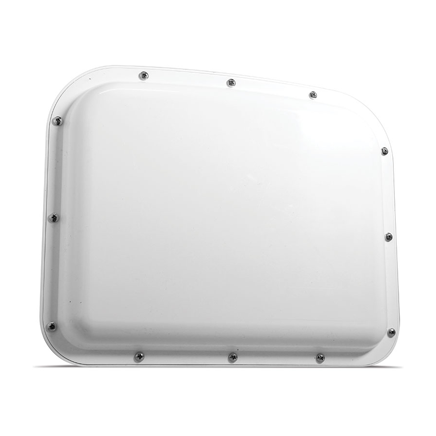
Page 8: Introduction
Figure 1. SmartSensor HD This guide will cover selecting a mounting location for, installing, and configuring a SmartSensor HD. To find the instructions for specific tasks, see the table of contents. If your questions aren’t answered in this guide, visit www.wavetronix.com/support for access to supplemental materials, like technical documents and troubleshooting information. - Page 9 Wavetronix, will void the customer warranty. Wavetronix is not liable for any bodily harm or damage caused if unqualified persons attempt to service or open the back cover of this unit. Refer all service questions to Wavetronix or an authorized distributor. Important note Failure to follow the installation guidelines laid out in this guide could result in decreased performance.
-
Page 10: Choosing A Mounting Location
Choosing a Mounting Location Mounting location, height and, offset Choosing where to mount Figure 2. The HD’s radar footprint The SmartSensor HD is a side-fire radar detector. It uses dual ˿ radar beams to get highly accurate presence, speed, and length data. - Page 11 Keep cable lengths in mind when you pick mounting locations; ˿ when you use the Wavetronix cable, cables can be as long as 600 ft. (182.9 m) if you’re using 24 VDC and RS-485 communi- cations; for longer connections, consider alternate wired and wireless options.
-
Page 12: Choosing A Mounting Height And Offset
Choosing a mounting height and offset Mounting guidelines in feet Definition. Mounting height is the distance Offset Height (acceptable range) between the sensor * reduction (9–19) and the road’s in number (9–19) of reported height, not the (9–20) speeds. bottom of the pole. If (9–21) installing a new pole, (9–22) - Page 13 For best results, choose the mounting height in the Height ˿ that range could column in the table. If you can’t, just keep it somewhere in the negatively affect acceptable range. sensor accuracy. SmartSensor HD User Guide •...
-
Page 14: Occlusion And Multipathing
Occlusion and multipathing These are two problems you might face while using a radar detector. Figure 4. Occlusion Occlusion occurs when one object blocks another object from the sensor’s view, as shown above. This can happen with Tall vehicles like semi trucks ˿... -
Page 15: Fixing Occlusion Problems
A 30-ft. (9.1-m) lateral separation would be ideal, but even just a few feet can make a difference. Adjust the sensor’s sensitivity thresholds in SmartSensor Man- ˿ ager HD, as covered in chapter 7. SmartSensor HD User Guide •... -
Page 16: Installing The Smartsensor Hd
Once you're ready to mount the sensor on the pole: insert the Chapter 2: Installing the SmartSensor HD •... -
Page 17: Aligning The Sensor To The Roadway
Figure 7. Up-and-down positioning Tilt the sensor down so the front is aimed at the center of the detection area. Figure 8. Side-to-side positioning Adjust the side-to-side angle so it’s perpendicular to the flow of traffic. SmartSensor HD User Guide •... -
Page 18: Applying Silicon Dielectric Compound
Figure 10. Applying the compound Tear the tab off the tube of silicon dielectric compound that came with the sensor. Squeeze about half of the compound on the connector at the base of the sensor. Chapter 2: Installing the SmartSensor HD •... -
Page 19: Connecting The Cable
If there’s excess cable, don’t cut it, as you may need it at a later time; leave it in the pole. SmartSensor HD User Guide •... -
Page 20: Installing Power, Surge Protection, And Communications
If you need more information, contact support@ wavetronix.com. Figure 12. Installation with pole-mount box and no cabinet Chapter 3: Installing Power, Surge Protection, and Communications •... -
Page 21: Setting Up The Pole-Mount Box
Find the mounting brackets that were included in the package and attach them to the back of the Standard Preassembled Cabinet. Use Band-It or a similar clamping system to attach the Standard Preassembled Cabinet to the pole. SmartSensor HD User Guide •... - Page 22 485- 485+ Figure 15. Connecting power cable to terminal blocks Insert the power cable through the leftmost cable grip on the bottom of the box. Twist the cable grip to tighten. Insert the black conductor into the round hole on the plug por- tion of the L terminal block (do not strip the insulation).
- Page 23 Follow the instructions in step 4 to land each conductor into the correct terminal block. The blocks are color-coded for your convenience: land the red conductor into the block with the red label, and so on. SmartSensor HD User Guide •...
- Page 24 485- 485- 485+ 485+ Figure 17. Connecting earth ground Connect the grounding lug to earth ground. More information about this setup Warning. For installs with only the pole- This cabinet is designed to be mounted on a pole and to provide mount box (no traffic everything your sensor needs: cabinet), you need...
-
Page 25: Installations With A Pole-Mount Box And Traffic Cabinet
295, How to Assemble the Power Plant. If you are not using Wavetronix devices, 485- 485+ 485- 485+ contact your dealer or visit the knowledge base at www.wavetronix.com. Figure 19. Surge Preassembled Cabinet (pole-mount box) SmartSensor HD User Guide •... - Page 26 Lightning Surge Protection Figure 20. Attaching the pole-mount box Find the mounting brackets that were included in the pack- age and attach them to the back of the Surge Preassembled Click! Cabinet. Use Band-It or a similar clamping system to attach the Surge Preassembled Cabinet to the pole.
- Page 27 Follow the instructions in steps 4 and 5 to land each conductor into the correct spots in the set of terminal blocks marked “To Traffic Cabinet,” remembering to follow the color-coded labels. 485- 485+ 485- 485+ 485- 485+ 485- 485+ Figure 23. Connecting earth ground SmartSensor HD User Guide •...
-
Page 28: Setting Up The Traffic Cabinet
Connect the grounding lug to earth ground. Setting up the traffic cabinet Note. This section assumes you are using the Standard Preassembled Backplate from Wavetronix; if you Lightning Surge Protection bought individual Click modules instead, see Click 100–400 Series User... - Page 29 Figure 26. Connecting power cable to terminal blocks Start by connecting the power cable. This backplate is shipped from Wavetronix with the conductors in the cable already ter- minated in a terminal block plug. Insert this plug into the power terminal blocks.
- Page 30 Warning. Using two Click 200s is one at either end of the underground cable run. This protects standard Wavetronix all the equipment, especially the sensor, from power surges on procedure for the cable, such as those caused when lightning hits the ground underground near where it’s buried, which makes these very important! It’s...
-
Page 31: Connecting To The Sensor
HD sensor. It can only be installed on a PC. Downloading SSMHD Figure 28. Finding the SSMHD download on the Wavetronix website In a browser, navigate to www.wavetronix.com/en/support. From the Detection drop-down menu, select SmartSensor HD. -
Page 32: Installing Ssmhd
SmartSensor Manager HD vX.X.X Setup. If you are prompted, click the Download button. Installing SSMHD Note. You must have administrator rights to install the program, as well as Microsoft .NET Framework version 3.5. Figure 29. SSMHD install wizard Double-click on the setup file. Follow the instructions on your screen to choose where to install, and then to choose which shortcuts to create. -
Page 33: Changing The Software Language
SmartSensor Manager can connect to your sensors via a serial (RS- 232 or RS-485) or Internet (IP address) connection; this may require additional equipment. There is also a virtual option for testing or demo purposes. SmartSensor HD User Guide •... -
Page 34: Making A Serial Connection
From the Speed drop-down, choose 9600 bps (the default rate Search and it will for the SmartSensor HD), unless you have previously changed cycle through all the baud rate of the sensor. available COM ports Click Connect. -
Page 35: Making An Internet Connection
˿ terminal server, leave this set to Isolated Sensor. If the terminal server can see several sensors, set this to Multi-drop Network and enter the sensor ID of the sensor you want to connect to. SmartSensor HD User Guide •... -
Page 36: Making A Virtual Connection
If you make changes to the sensor’s setup while using a virtual connection, those changes are saved to the virtual sensor file, which by default will be saved to C://ProgramFiles/Wavetronix/ SmartSensorManagerHD vX.X.X/bin/. If you want, you can back up those virtual sensor settings; that will create a sensor setup file which can then be restored to an actual sensor. -
Page 37: Troubleshooting A Connection
Make sure the sensor ID is correct. ˿ Make sure the terminal server is configured properly. ˿ If a failure occurs repeatedly, contact support@wavetronix.com. ˿ Advanced communication tools Once you’ve made a connection, the Connect button of the main screen should now be animated, with arrows moving past each other, and it should now say "Connected."... -
Page 38: Using The Address Book
Click on the notepad icon at the bottom of the connection screen (serial, Internet or virtual). The error log will be saved to C://ProgramFiles/Wavetronix/ SmartSensor Manager HD vX.X.X/bin. It will also open in your default .txt editor. If you need to save a copy for troubleshooting purposes, do a Save As, as the file will be written over next time you view an error log. -
Page 39: Password-Protecting The Sensor
Figure 40. Forgotten Password window When you’re prompted to enter the password, you’ll see a link you can click if you’ve forgotten the password you chose. It tells you to contact Wavetronix technical support and what information to give them. SmartSensor HD User Guide... -
Page 40: Updating The Sensor
Updating the sensor Figure 41. Version Control basic screen and detailed screen If the version of SSMHD doesn’t match the version of the sen- sor’s embedded firmware, then after you click Connect, the Version Control screen will appear. If you would like specifics on the mismatch, click the Details >> button. - Page 41 Downgrading the sensor Figure 43. Downgrade warning message If the downgrade message appears, it means that the sensor firm- ware is newer than the version of SSMHD you’re using. Get the newest version of SSMHD from www.wavetronix.com. SmartSensor HD User Guide •...
-
Page 42: Configuring Sensor Settings
Configuring Sensor Settings Figure 44. Settings button, main screen Access the sensor settings by clicking Settings on the main screen. Changing these settings is optional; if you leave them set to their defaults, the sensor will still function. Chapter 5: Configuring Sensor Settings •... -
Page 43: Changing General Tab Settings
Limit of 32 useful in identifying characters. the sensor later. Location Lets you enter the Change this if you sensor’s location. think you’ll find it Limit of 32 characters. useful in identifying the sensor later. SmartSensor HD User Guide •... - Page 44 Setting Description Details Orientation Lets you mark which Change this if you direction the sensor is think you’ll find it pointing. useful in identifying the sensor later. Units Sets whether the Purely for your software displays convenience—does distances in standard not affect sensor (mph/feet), metric performance.
-
Page 45: Changing Ports Tab Settings
Default is 10 ms. transmission direction. Termination Electronically You don’t need to turns RS-485 change this unless communication bus a multi-drop bus termination on or off. becomes overloaded. SmartSensor HD User Guide •... - Page 46 SSMHD is communicating over the RS-232 line. Speed Lets you change the All Wavetronix baud rate for this devices default to comm link. 9600 bps. Response Delay Lets you set how long Change this if the sensor will wait you’re using a...
-
Page 47: Changing Outputs Tab Settings
(creates simulated traffic). RF Channel Lets you change If you’re using which radio frequency multiple sensors channel the sensor is within 70 feet of each transmitting on. other, set each to its own RF channel. SmartSensor HD User Guide •... - Page 48 Size & Spacing Makes your system Use this if you used occupancy numbers emulate a system the SmartSensor HD in the interval with inductive loops. to replace loops, data, but adjusting These settings are and the rest of...
-
Page 49: Changing Data Tab Settings
Details Max Vehicle Length Lets you set your Change this if your maximum vehicle roads have a max length; any detected vehicle length. vehicle that exceeds this length is reported as being only this long. SmartSensor HD User Guide •... -
Page 50: Configuring Lanes
Configuring Lanes Figure 49. Lanes button, main screen Click the Lanes button on the main screen to open the Lanes screen, then click the Configuration button to open the Configura- tion screen. Chapter 6: Configuring Lanes •... -
Page 51: Alignment
Figure 50. Lanes screen Alignment Sidebar Sidebar button View menu Alignment arrow Figure 51. Alignment tools SmartSensor HD User Guide •... -
Page 52: Checking Sensor Alignment
Checking sensor alignment Note. Lane configuration won’t work as well as it should if the sensor is misaligned, so don’t skip this step! Figure 52. Good, mediocre, bad, and very bad alignment (left to right) Be sure traffic is flowing freely on the road in order to get this tool to work best. -
Page 53: Lane Configuration
If there’s no traffic on the road, you may need to drive your own vehicle back and forth in front of the sensor a few times. Figure 55. Automatic Lane window SmartSensor HD User Guide •... -
Page 54: Excluding Or Including A Lane Or Area
Open the Tools menu by clicking the hammer and wrench icon, then select Clear Edit Area. Click on the sidebar button until sidebar 1 appears. Open the Tools menu again and select Restart Auto Cfg. Let the configuration process run (this could take a few sec- onds to a few minutes) until all of the lanes have been found by SSMHD;... -
Page 55: Adding A Lane
Figure 58. Lane window but you can use the lowercase Click on the lane you want to edit. The Lane window will appear. version, “Lane_xx”, Change the Name field at the top. if you’d like. SmartSensor HD User Guide •... -
Page 56: Deleting A Lane
Click the X in the upper right corner to save and close the window. Deleting a lane Click on the lane you want to delete. The Lane window will appear. Click Delete. Be aware that if the lane was automatically config- ured, and if Show Auto Lanes is turned on, once it is deleted it will still appear as a blue automatic lane. -
Page 57: Viewing Sidebars
Automatic Configuration. Or use the automatically configured lanes as a reference—to see where the software has detected lanes— while you’re manually configuring or adjusting lanes. SmartSensor HD User Guide •... - Page 58 Setting Description Details Shows the lanes that Use the lanes (Saved have been saved, in currently saved configuration) black. to the sensor as a reference—to see where the lanes have previously been saved at—while you’re manually configuring or adjusting lanes. Shows a ruler Use this to measure (Scale)
-
Page 59: Using The Automatic Lane Sidebar Window
Use this if, during the halts the automatic configuration process, configuration process; there are traffic no new lanes will be events you don’t placed until you click want to be part of the again to resume. sensor’s calculations. SmartSensor HD User Guide •... -
Page 60: Using The Saved Lane Sidebar Window
Sidebar 1 shoulder area window If you click the shoulder area, instead of a lane, it will open a window with just the range/width of the shoulder and the Copy Sidebar option. Using the Saved Lane sidebar window Figure 62. Sidebar 2 (saved configuration) window When sidebar 2 (saved configuration) is open, click on one of the lanes in the sidebar to open this window. -
Page 61: Using The Vehicle Display Menu
Copy Sidebar option. Using the Vehicle Display menu Figure 63. Choosing vehicle display options Click the vehicle display button (dark blue car on a teal back- ground) to change how the detected vehicles are displayed. SmartSensor HD User Guide •... - Page 62 Setting Description Details Display vehicles by: Determines where Range is more Note. The text next detected vehicles are useful as an accurate to this button shows what units the speed displayed: Range (the depiction of what’s and length are default) means the being detected, displayed in (feet/ vehicles are displayed...
-
Page 63: Using The Tools Menu
Does not choose Hide Auto clear automatically Lanes from the View configured lanes, menu or Automatic however. Lane window. Even then, they’re not deleted, just hidden. SmartSensor HD User Guide •... - Page 64 Setting Description Details Save To File & Load Let you save lane Use these if you’re Note. This only saves From File configuration replacing an old HD lane configuration settings to file. Saving information to a file on with a new one and all configuration your computer, and don’t want to do the...
-
Page 65: Using The View Menu
Names of the text on the convenience and lanes. doesn’t affect sensor operation. Show/Hide Direction Changes the display This setting is for your of the arrows on the convenience and lanes. doesn’t affect sensor operation. SmartSensor HD User Guide •... -
Page 66: Using The Automatic Lane Window
Setting Description Details Show/Hide Compass Shows or hides a This setting is for compass that shows your information and which direction the doesn’t affect sensor sensor is pointing. operation. This is completely user-set; the information comes from the Orientation field under Settings, so if you didn’t change that setting, this will default to... - Page 67 To include the area easily be included again, click it to open again, while a deleted the Excluded Area lane will have to be window and click reconfigured. An Include. excluded area will turn red. SmartSensor HD User Guide •...
-
Page 68: Using The Lane Window
Using the Lane window Figure 67. Lane window Click a saved (black) lane in the edit area to open this window. Setting Description Details Name Lets you type in a SSMHD uses “LANE_ Note. If you decide new lane name. xx”... - Page 69 (useful for lanes that change direction at certain times of day, such as those that change to match commuter traffic at the beginning and end of the work day). SmartSensor HD User Guide •...
- Page 70 Setting Description Details Range & Width Shows and changes Change these values the size and with the arrows or placement of the lane by typing in order to (Range refers to the manually fine-tune distance from the your lane placement sensor).
-
Page 71: Using The Shoulder Area Window
Add Lane Creates a new lane in Unlike automatically the spot you clicked configured lanes, which are blue when they first appear, user-created lanes will appear black. SmartSensor HD User Guide •... -
Page 72: Using The Excluded Area Window
Setting Description Details Exclude Tells the sensor This may be useful to ignore the area in order to ignore you clicked on; phantom detections detections there from multipathing. An won’t affect alignment excluded area will or configuration. turn red. To include the area again, click it to open the Excluded Area window and click... - Page 73 Include Area Restores the area When you include or lane that was a lane that was previously excluded. previously excluded, it may reappear as an automatic lane; click on it to capture it. SmartSensor HD User Guide •...
- Page 74 Verifying Lanes Figure 70. Lanes button, main screen Click the Lanes button on the main screen to open the Lanes screen, then click the Verification button to open the Verification screen. Chapter 7: Verifying Lanes •...
- Page 75 If the actual traffic matches the software traffic, your lanes are set up properly. SmartSensor HD User Guide •...
- Page 76 If all else fails, contact your dealer or support@ option here. If you wavetronix.com. don’t have them set up, class will be Verifying lanes using sidebars grayed out in this menu.
- Page 77 You may find it useful to use these buttons to pause or restart the speed and volume counts on the sidebars. For instance, using the example in step 3 above, you could do the following: SmartSensor HD User Guide •...
- Page 78 Open the volume sidebar, then click the stop button to stop the counts. Once there is a large gap in the traffic in lane 1, click the play button. This will restart the counts at 0. Count vehicles in lane 1 manually until there is another large gap in the traffic.
- Page 79 In the lower right corner of the Verification screen, next to the word “Logging,” click the upward-pointing arrow. The Logging area will appear, as seen above. SmartSensor HD User Guide •...
- Page 80 You can also navigate to the file on your computer: C://ProgramFiles/ Wavetronix/SmartSensor Manager HD vX.X.X/bin. The file that was created will be a .csv spreadsheet that can be opened in Microsoft Excel.
- Page 81 You’ll likely need to adjust at least 10–15% in either direction (possibly much more); adjusting less may not impact detections. We recommend you keep the slider between 20 and 190%. SmartSensor HD User Guide •...
- Page 82 Contact Wavetronix for more Increasing the information regarding decibels raises the thresholds and how threshold and results to adjust them.
- Page 83 After you enter a value, the sensor automatically determines the extension time and then multiplies it by your entered value. SmartSensor HD User Guide •...
- Page 84 Setting Description Details Direction Protection Determines whether By default, Direction Note. If Direction the software reports Protection is turned Protection is on, wrong-way vehicles or ignores any on for each lane will not be shown vehicles that are (although if you set a moving across the traveling the opposite lane as bi-directional,...
- Page 85 Setting Up and Downloading Sensor Data Figure 76. Data button, main screen Click the Data button on the main screen to open the Data screen. SmartSensor HD User Guide •...
- Page 86 Figure 77. Data screen Definitions Figure 78. Definitions screen This screen lets you define interval length, bins (class, speed and direction) and approaches. You can set all, some or none of these definitions simultaneously. How you set these will affect your sensor’s onboard storage—the more definitions you have set, the larger the records will be, and the faster the onboard memory will fill up.
- Page 87 66 and 85 miles per hour. are deleted first. To delete a bin, highlight it and click the – button at the top of the Speed area. SmartSensor HD User Guide •...
- Page 88 Creating, adjusting and deleting class bins Definition. A class bin is a classification of a vehicle based on its length (usually a range of lengths); which length bin a detection falls into is part of the data collected about it. For interval data, the sensor records how Figure 80.
- Page 89 If you would like the intervals that are reporting zero volume to report speeds as zero, simply check the If volume = 0, speed = 0 checkbox. Interval Data Figure 83. Interval Data screen, Lanes tab SmartSensor HD User Guide •...
- Page 90 Access the Interval Data screen by clicking the Interval Data Note. Logging interval data is useful button on the Data screen. This screen lets you log interval data for verifying your (data collected about all detections in a given interval of time) for sensor setup—just both lanes and approaches.
- Page 91 Classes – How many vehicles fell into each of the length-, ˿ speed- and direction-based bins set on the Definitions screen. Storage Figure 85. Storage screen Access the Storage screen by clicking the Storage button on the Data screen. SmartSensor HD User Guide •...
- Page 92 Understanding data storage tools Setting Description Details On/off switch Turns interval data Turn this on for normal storage on or off. data collection. Stop when FULL Sets the sensor to Use this if you don’t stop storing data want old data to be once the storage overwritten by new capacity is reached,...
- Page 93 In the latter case, the green status bar will be a better indicator of storage capacity. Download Access the Download screen by clicking the Download button on the Data screen. Figure 86. Download screen SmartSensor HD User Guide •...
- Page 94 Downloading stored detection data Note. You can view a list of previous Type a name for your download in the Name text field. data downloads by If you want all the data currently on the sensor, keep the Down- clicking the green Downloads arrow load all of the data checkbox checked.
- Page 95 There are three formats you can view or export the downloads in: a comma-delimited (.csv) file, a Microsoft Excel file, or a Wavetronix-specific text format that opens in a text editor like Notepad. To view the downloaded data, click the desired for- mat’s icon on the View: (choose format) line.
- Page 96 Push Figure 89. Push screen Access the Push screen by clicking the Push button on the Data screen. This function lets you push data from the sensor without waiting for a request from SSMHD. You can push event, interval or presence data.
- Page 97 SmartSensor HD in for 125 ms for each a system that was vehicle detected, so designed for dual only speed will be inductive loops and measured. all you need is vehicle presence and speed. SmartSensor HD User Guide •...
- Page 98 HD (legacy) Emulates the interval Use this when data from older you’re using a newer versions of this SmartSensor HD in sensor; it’s similar to a system that was the HD format but designed for an older lacks speed bins and SmartSensor HD.
- Page 99 If you’d rather just broadcast the pushed data, click the Broad- the destination to 000/00000. cast checkbox to push the data to the broadcast address (000/65535 for SS125 and 16777215 for Z4). Click OK to finish. SmartSensor HD User Guide •...
- Page 100 Using Tools Figure 90. Tools button, main screen Click the Tools button on the main screen to open the Tools screen. Chapter 9: Using Tools •...
- Page 101 Figure 91. Tools screen Backing up and restoring sensor setup files Figure 92. Backup-Restore screen SmartSensor HD User Guide •...
- Page 102 Setting Description Details Backup File Allows you to create This may be useful a backup file (.ssc) of if you are making the sensor settings changes to the you currently have sensor and want configured. to back up your configuration before Click the magnifying you do so, so that you glass to navigate to...
- Page 103 License File Currently not in use. SmartSensor HD User Guide •...
- Page 104 Accessing power options Figure 94. Power screen Setting Description Details Power Up / Power Shows the timestamp May be useful for Down of the last time the diagnostic purposes, sensor powered up or to see if the sensor down. has lost power at some point.
- Page 106 INDEX SYMBOLS 85th percentile speed 87, 90 data .NET Framework 31 definitions. See Definitions screen (Data) downloading. See Download screen (Data) interval. See Interval Data screen (Data); See interval adapter, USB to serial 34 per vehicle. See per vehicle data address book 37–40 push. See Push screen (Data) alignment 50–72, 63, 65 storage.
- Page 107 installation type 33, 34 password 38 Internet 34 per vehicle data 74, 77–78, 87 Internet Connection screen 34 pole 10, 11, 14, 15, 18, 19–20, 24–25 interval pole-mount box. See Standard Preassembled Cabi- configuration 86, 92 net; See Surge Preassembled Cabinet data 88–90, 91 port 33, 34, 36, 95 data push 95–98 Ports tab (Settings) 44–45 interval data logging 89–90 power 19, 21, 24, 28, 103...
- Page 108 speed bins 85–86 Standard Preassembled Backplate 27–29 Standard Preassembled Cabinet 20–23 Storage screen (Data) 90–92 subnet/ID 36, 42, 98 Surge Preassembled Cabinet 24–27 surge protection 8, 19, 23, 29 terminal blocks 21–22, 25–26, 28–29 terminal server 34, 36 termination 44 thresholds 14, 75, 76, 78, 79, 81 time 43 timeout 33, 34 Tools screen 99–103 traffic cabinet 10, 24–29 trees 10, 13 troubleshooting 36, 37, 51...
- Page 109 www.wavetronix.com...
Need help?
Do you have a question about the SmartSensor HD and is the answer not in the manual?
Questions and answers