
Subscribe to Our Youtube Channel
Related Manuals for Hydronix Hydro-Control VI

Summary of Contents for Hydronix Hydro-Control VI
- Page 1 Hydro-Control VI Operators Guide To re-order quote part number: HD0456 Revision: 1.7.1 Revision date: August 2020...
- Page 2 CUSTOMER FEEDBACK Hydronix is continually looking to improve not only its products but also the services that we offer to our customers. If you have any suggestions about how we can do this or if you have any other feedback that would be helpful please complete our short form at www.hydronix.com/contact/hydronix_feedback.php.
- Page 3 +1 888 887 4822 (Toll Free) +1 231 439 5001 European Office Covers Central Europe, Russia and South Africa Tel: +49 2563 4858 Fax: +49 2563 5016 French Office Tel: +33 652 04 89 04 Hydro-Control VI Operators Guide HD0456 Rev 1.7.1...
- Page 4 Hydro-Control VI Operators Guide HD0456 Rev 1.7.1...
- Page 5 V2.0.0.0 December HS0085 v2.0.0.0 extra functionality added 2011 V1.4.0 V2.5.0.0 March 2014 HS0085 v2.5.0.0 extra functionality added Reference to the Hydro-Control VI Database Editor added V1.5.0 V2.8.0.0 October 2015 HS0102 sensor firmware features added V1.6.0 V2.9.0.0 August 2016 Recipe Editor Calibration Mix viewer added. Mix Log details updated.
- Page 6 Hydro-Control VI Operators Guide HD0456 Rev 1.7.1...
-
Page 7: Table Of Contents
Table of Contents Chapter 1 Introduction ........................... 11 Introduction to the Hydro-Control VI ................... 11 About this Manual ........................12 Chapter 2 Navigation ..........................13 Applying Power .......................... 13 The Overview Screen ......................... 13 User Login / Logout ........................14 The Main Menu .......................... - Page 8 Hydro-Control VI Operators Guide HD0456 Rev 1.7.1...
- Page 9 Table of Figures Figure 1: The Hydro-Control VI ......................11 Figure 2: The Overview Screen of the Hydro-Control VI ..............13 Figure 3: The Menu Screen ........................15 Figure 4: The Recipe Overview Screen ....................16 Figure 5: The Mix Log screen ....................... 17 Figure 6 - Recipe/Mode Screen ......................
- Page 10 Hydro-Control VI Operators Guide HD0456 Rev 1.7.1...
-
Page 11: Chapter 1 Introduction
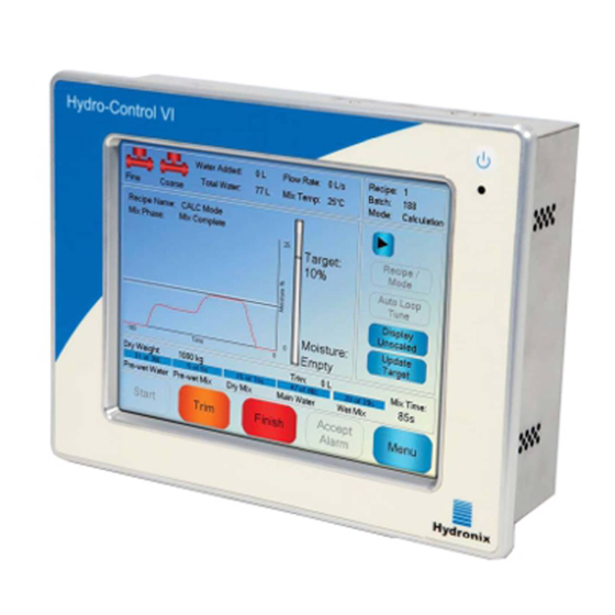
Figure 1: The Hydro-Control VI 1 Introduction to the Hydro-Control VI The Hydro-Control VI is a touch screen computer based upon the Microsoft Windows XP Embedded operating system that has been designed to work with the Hydronix range of sensors. -
Page 12: About This Manual
Hydro-Control VI. The manual is divided into chapters which cover setting up recipes in and using the Hydro-Control VI to make concrete. Chapter 2 describes how to navigate around the Hydro-Control VI and Hydro-Control VI introduces the system... -
Page 13: Chapter 2 Navigation
Navigation 1 Applying Power The Hydro-Control VI is switched on by pressing the power button in the top right hand corner of the unit. The blue light below will illuminate and the unit will boot up the control system. The unit will first display two self-test screens and will then boot the Windows XP Embedded Operating System. -
Page 14: User Login / Logout
Once a user has logged in, the Log In button on the Overview Screen will change to a Log Out button. When a user has finished using the Hydro-Control VI, they should press the Log Out button . The Log Out button will revert back to the Log In button and the menu button in the bottom right hand corner will be greyed out, indicating that it is disabled. -
Page 15: The Main Menu
Allows configuration and test of the inputs and outputs. Configuration instructions are detailed in the Installation Guide (HD0455). Sensor Configuration Displays the sensor configuration screen allowing changes to the filtering and analogue output. Configuration instructions are detailed in the Installation Guide (HD0455). Hydro-Control VI Operators Guide HD0456 Rev 1.7.1... -
Page 16: The Recipe Overview
Edit Recipe button (4). To delete a recipe, select it in the list and then press the Delete Recipe button (5) To select the next recipe to be run, change the next recipe parameter (6). Hydro-Control VI Operators Guide HD0456 Rev 1.7.1... -
Page 17: The Mix Log
Most of the system parameters will have been set up by the person installing the system and are detailed in the Installation Guide (HD0455). For day to day operation, the operator of the system should be familiar with the water addition modes, Auto-track and the system alarm parameters. Hydro-Control VI Operators Guide HD0456 Rev 1.7.1... - Page 18 Navigation Chapter 2 Hydro-Control VI Operators Guide HD0456 Rev 1.7.1...
-
Page 19: Chapter 3 Plant Operator Controls
The procedure for this is described in Chapter 8 section 2.8. For detailed descriptions of each parameter see Chapter 6. Hydro-Control VI Operators Guide HD0456 Rev 1.7.1... - Page 20 Plant Operator Controls Chapter 3 Hydro-Control VI Operators Guide HD0456 Rev 1.7.1...
-
Page 21: Chapter 4 Understanding The Mix Cycle
Main Water Mix Phase Load mixer Dry Mix Time Wet Mix Time Discharge Mixer Addition Time Signals From PLC START To PLC COMPLETE Figure 7: A simple mix cycle Hydro-Control VI Operators Guide HD0456 Rev 1.7.1... -
Page 22: Pre-Wet Water
If using the “Pre-wet Done” signal it is best practice to pause the Hydro-Control until the cement has finished loading. For this the Hydro-Control VI has an input called “Cement In”. After the “Pre-wet Done” output is given, the Hydro-Control waits for the “Cement In” before continuing onto the Dry Mix phase. -
Page 23: Figure 8: The Mix Cycle With Pre-Wet
Figure 8: The mix cycle with pre-wet The Hydro-Control VI starts its cycle when the “Start” signal is received. The first phase is the addition of the Pre-wet Water followed by the mix time defined in the parameter “Pre-wet Mix Time”. - Page 24 • Some SCC admixes In these situations the Hydro-Control VI can be configured to calculate an amount of water to add based on a reading with either just aggregates or aggregates and water added. Once water has been added to a fixed moisture content it is then optional whether an additional calculation is made to add the main water or whether a pre-set amount of water, scaled for changes in the dry weight is added.
-
Page 25: Chapter 5 Water Addition Modes
If the final product homogeneity is not important, for example if there is further processing after the mixer, then the Wet Mix Time can be decreased. Hydro-Control VI Operators Guide HD0456 Rev 1.7.1... -
Page 26: Auto Mode
To use CALC Mode the dry weight recipe parameter would have to be updated on a batch by batch basis, either by sending it using the RS232 port on the Hydro-Control VI, or by manually editing the recipe. •... -
Page 27: Chapter 6 Editing Recipes
Recipe Details Recipe parameter Description Recipe Number This is the number of the recipe in the Hydro-Control VI. Batch Number This is the number of the last batch made. Recipe Name This is the name of the recipe which is displayed on the Overview Screen. - Page 28 Wet Mix Time This is the amount of time to mix after the main water has been added before signalling Mix Complete. Using the Next button will give page 2 of the recipe editor screen. Hydro-Control VI Operators Guide HD0456 Rev 1.7.1...
-
Page 29: Figure 12: The Recipe Editor Screen
Unscaled Mode This indicates the sensor measurement mode used for the recipe. Hydro-Control VI Operators Guide HD0456 Rev 1.7.1... - Page 30 Dry Mix Time the system will prompt the operator to continue regardless of whether it has stabilised or not. Dry Mix Deviation This is the maximum deviation that the sensor signal must be within in order for the system to continue. Hydro-Control VI Operators Guide HD0456 Rev 1.7.1...
-
Page 31: Figure 13: The Recipe Editor Screen
Use Pre-wet value for main If enabled the Hydro-Control VI will use the reading measured at water the end of the pre-wet mix rather than the dry mix to calculate how much water to add in the main water addition Hydro-Control VI Operators Guide HD0456 Rev 1.7.1... - Page 32 Admix Amount Not used by the Hydro-Control but appears in the Recipe. This is the amount of admix stated in the mix design. This can be manually input for information only. Hydro-Control VI Operators Guide HD0456 Rev 1.7.1...
- Page 33 Temperature Set Point that is added to or subtracted from the target unscaled. This is used to allow the concrete to vary depending on the temperature to allow for the increased rate of hydration in hotter atmospheres. Hydro-Control VI Operators Guide HD0456 Rev 1.7.1...
- Page 34 Editing Recipes Chapter 6 Hydro-Control VI Operators Guide HD0456 Rev 1.7.1...
-
Page 35: Chapter 7 Running The First Mix
This is the amount of water to add during the pre-wet phase. Main Water This is the fixed amount of water to add during the main water addition when running in Preset mode. Dry Mix Time This defines the dry mix time. Hydro-Control VI Operators Guide HD0456 Rev 1.7.1... -
Page 36: Setting The Recipe For The First Mix
90 100 110 120 130 140 150 160 Moisture Mixer Dry Mix Water Wet Mix Discharge Loading Addition Time 90 100 110 120 130 140 150 160 Figure 15: Extending the mix times for calibration Hydro-Control VI Operators Guide HD0456 Rev 1.7.1... - Page 37 These will be reduced later when the performance of the mixer is evaluated. Enter the Dry Weight, Pre-wet and Cement Timeout (if used). Select Finish to return to the Recipe Overview screen. Press Hydro-Control VI Operators Guide HD0456 Rev 1.7.1...
- Page 38 The water valve will remain open until the button is released. Repeat the previous step until the mix is at the desired consistency, and then press the Finish Press button. Hydro-Control VI Operators Guide HD0456 Rev 1.7.1...
- Page 39 Wet Mix. If the signal is not stable then increase the mix times and run another batch to check the stability. It may be advantageous to extend the mixing times to be able to ascertain the point at which the signal becomes stable. Hydro-Control VI Operators Guide HD0456 Rev 1.7.1...
- Page 40 Running the First Mix Chapter 7 Hydro-Control VI Operators Guide HD0456 Rev 1.7.1...
-
Page 41: Chapter 8 Using Moisture Control
It is always best to view deviations in unscaled units as this is not affected by any calibration values that are defined in the recipe. Hydro-Control VI Operators Guide HD0456 Rev 1.7.1... -
Page 42: Calc Mode
The previous chapter details how to run the first batch. The Hydro-Control will then use the data recorded during the batch to generate a calibration for the recipe to use with further batches. Hydro-Control VI Operators Guide HD0456 Rev 1.7.1... - Page 43 This mode allows the user to calculate both the pre-wet water. It also allows the main water to be calculated from the pre-wet mix value in the situation where the dry mix does not stabilise quickly. Hydro-Control VI Operators Guide HD0456 Rev 1.7.1...
- Page 44 0.5. For sensors with multiple measurement modes check the deviation for each available mode. Press View Mix Trace. Press Press the Calibrate button. Press Choose which calibration mode is most appropriate for the mix and press OK Hydro-Control VI Operators Guide HD0456 Rev 1.7.1...
- Page 45 Press the Menu button and then the Overview button to return to the Overview Screen. After calibration it is always good practice to monitor the following batches of the same recipe and to check the strength and quality of the mix output. Hydro-Control VI Operators Guide HD0456 Rev 1.7.1...
-
Page 46: Figure 19: The Calc Mode Calculation
In order to achieve an accurate calibration the following values must be known: Batch weight • Quantity of water added • An accurate Dry Mix sensor reading • • An accurate Wet Mix sensor reading (which also gives the target value) Hydro-Control VI Operators Guide HD0456 Rev 1.7.1... -
Page 47: Figure 20: The Calibration Failed Error Message
100 Unscaled. However, the blue trace has the greatest difference between the dry and wet mix phase so is selected to be used for the calibration. For advice on selecting the Measurement mode contact the Hydronix support team at support@hydronix.com... - Page 48 Hydro-Control VI Operators Guide HD0456 Rev 1.7.1...
-
Page 49: Auto Mode
When a recipe is created the Hydro-Control uses a default calibration to calculate the moisture for display. Some operators prefer to use an arbitrary value for the moisture target such as 10% and to use this to monitor repeatability and deviation. Hydro-Control VI Operators Guide HD0456 Rev 1.7.1... -
Page 50: Figure 24: The Effect Of Changing The Proportional Gain
As can be seen from Figure 24, if the Proportional Gain is set too high then the moisture will overshoot the target value. If the Proportional Gain is set too low then the water is added to slowly and the moisture will take too long to get to the target value. Hydro-Control VI Operators Guide HD0456 Rev 1.7.1... -
Page 51: Figure 25: The Effect Of Changing The Integral Gain
Figure 26: The effect of changing the Derivative Gain The Derivative Gain only needs to be changed if there is overshoot on the target that settles as the water is mixed in as shown in Figure 26. Hydro-Control VI Operators Guide HD0456 Rev 1.7.1... -
Page 52: Using Admixtures
Dry Mix Time Dry Mix Time repeated Discharge Loading Addition part 1 Addition part 2 Time Moisture Time From PLC START To PLC WATER ADMIX COMPLETE Figure 27: The 2 step preset mode cycle Hydro-Control VI Operators Guide HD0456 Rev 1.7.1... -
Page 53: Figure 28: The Calibration Lines From The 2-Step Preset Mode Cycle
If required the amount of Admixture can be entered here and will be reported in the Mix Log. Save the recipe changes, then press menu and then overview to return to the Overview Screen Press Hydro-Control VI Operators Guide HD0456 Rev 1.7.1... -
Page 54: Auto-Track
In CALC Mode the Auto-track Mix Deviation should be set small enough to ensure a stable reading is used as the basis for the water addition calculation. For example, a 0.1% deviation allows a 0.1% change in the water calculated. Hydro-Control VI Operators Guide HD0456 Rev 1.7.1... -
Page 55: Temperature Compensation
It should be noted that adjusting the water demand due to temperature will cause variation in the Water/Cement ratio. When setting up this parameter ensure that Water/Cement ratios will remain in tolerance for the working temperature range. If the temperature coefficient is set to zero this function is disabled. Hydro-Control VI Operators Guide HD0456 Rev 1.7.1... - Page 56 Using Moisture Control Chapter 8 Hydro-Control VI Operators Guide HD0456 Rev 1.7.1...
-
Page 57: Figure 30: Page 2 Of The System Parameters Screen
Chapter 9 Alarm Configuration The Hydro-Control VI has a number of alarms that may be configured to assist in managing, monitoring and controlling the mixing process. When an alarm is triggered the Hydro-Control displays a visual prompt on the screen to indicate the nature of the problem to the operator and give possible resolutions, the Alarm OPTO output is also activated to signal that a problem exists to the batch control system. -
Page 58: Chapter 9 Alarm Configuration
• The moisture level of the incoming aggregates. Reduce any Pre-wet water that is added. If no Pre-wet water is being added, then • consideration of the aggregate handling and storage is advised. Hydro-Control VI Operators Guide HD0456 Rev 1.7.1... - Page 59 In AUTO Mode this alarm is triggered if the water addition has reached the ‘Water Limit’ parameter defined in the recipe. Check: • The recipe ‘Water Limit’ parameter is high enough. • The AUTO Mode tuning should be adjusted to not overshoot the target value. Hydro-Control VI Operators Guide HD0456 Rev 1.7.1...
- Page 60 Ensure cables are of the required standard • Ensure that the cable screen is connected at the sensor end only. • Further information on cabling can be found in the sensor user guides. Hydro-Control VI Operators Guide HD0456 Rev 1.7.1...
-
Page 61: Chapter 10 Using The Mix Log
Using the Mix Log 1 Introduction The mix log records information on mix cycles that have been run with the Hydro-Control VI. The following information about each batch is stored: A log of the sensor reading taken once per second during the mix cycle. - Page 62 This is the deviation in the signal taken during the Averaging Time or Auto-track time at the end of the Dry Mix. Target Value %/US This is the final target value to be achieved for the recipe. Hydro-Control VI Operators Guide HD0456 Rev 1.7.1...
- Page 63 This is the total mix time, from the time that the start signal is received by the Hydro-Control to the time that the Hydro-Control activates the Mix Complete signal. Dry Weight Kg/lbs This is the dry weight of the batch. Hydro-Control VI Operators Guide HD0456 Rev 1.7.1...
- Page 64 This is the Derivative Gain value used during the batch if the system is running in Auto mode. Cement In Error A Cement In alarm was triggered during the batch. Water Meter Fault A Water Meter Fault alarm was triggered during the batch. Hydro-Control VI Operators Guide HD0456 Rev 1.7.1...
-
Page 65: Viewing The Mix Trace
To access details for a particular batch, select one of the batches from the list and then click the View Mix Trace button. This will then display the mix trace page, which provides a graphical Hydro-Control VI Operators Guide HD0456 Rev 1.7.1... -
Page 66: Figure 33: The Mix Trace Screen (Moisture%)
It is possible to view any significant actions in the mix by pressing the left and right scroll buttons. Figure 34: The Mix Trace Screen (Unscaled) Hydro-Control VI Operators Guide HD0456 Rev 1.7.1... -
Page 67: Backing Up And Restoring
4 Backing up and Restoring The Hydro-Control VI database, including the system parameters, recipes and mix logs, can be backed-up to a USB memory stick. This facilitates the restoring of the Hydro-Control VI in the event of a fault or user error. - Page 68 The Memory Stick can be removed at any point after the system has completely restarted and the Overview Screen is shown. Hydro-Control VI Operators Guide HD0456 Rev 1.7.1...
-
Page 69: Chapter 11 Setting Up User Accounts
To create a user press the create user button and add the information to the account editor screen. Press the textboxes to enter the user information and press the OK button when done. Figure 36 - User account editor screen Hydro-Control VI Operators Guide HD0456 Rev 1.7.1... - Page 70 Setting Up User Accounts Chapter 11 Hydro-Control VI Operators Guide HD0456 Rev 1.7.1...
-
Page 71: Chapter 12 Remote Support
If connected to an Ethernet network that allows an outbound connection to the Internet, it is possible to get remote support for the Hydro-Control VI. This enables the engineer offering the support to connect to the HC06 directly from a remote location. As the engineer at the remote location makes changes the operator will see what changes are being made and what screens are accessed. - Page 72 Remote Support Chapter 12 Hydro-Control VI Operators Guide HD0456 Rev 1.7.1...
-
Page 73: Chapter 13 Optimisation
Where possible, the cement should be added either at the same time or within a few seconds after the start of the addition of sand and aggregates. Combining the materials together in this way will greatly assist the mixing process. Hydro-Control VI Operators Guide HD0456 Rev 1.7.1... -
Page 74: Consistency
3 x 2.0m In CALC Mode, keep the dry mix time as long as possible to allow the required water to be • calculated correctly, to the detriment of the wet mix time if necessary. Hydro-Control VI Operators Guide HD0456 Rev 1.7.1... -
Page 75: Chapter 14 Frequently Asked Questions
Can I adjust the contrast on the display? There is no way of adjusting the contrast of the display on a Hydro-Control VI. If either the backlight or the contrast if faulty, then the unit will need to be repaired by Hydronix. - Page 76 It will be necessary to calibrate the new sensing arm to the sensor electronics, so that the air and water factory calibration settings are correct. This process is fully detailed in the Hydro- Probe Orbiter User Guide. The calibration can be performed using the Hydro-Control VI from the Sensor Configuration page.
- Page 77 The mix log is a very useful tool for diagnosing problems with the controller. It is also useful to know the recipe, system and control parameters. These can be transferred onto a USB Memory Stick by doing a Backup. The file can be emailed to Hydronix as an aid for diagnostics. _ _ _...
- Page 78 Frequently Asked Questions Chapter 14 My Hydro-Control VI needs to be sent for repair. If I get a service replacement how do I transfer all the parameters from the old to the new unit? All System, Recipe and Mix Log data can be downloaded from one Hydro-Control VI onto a USB Memory Stick and then uploaded to another unit.
-
Page 79: Appendix A Diagnostics
Diagnostics The following tables list the most common faults found when using the controller. If you are unable to diagnose the problem from this information, please contact Hydronix technical support on +44 1483 468900 or by email: support@hydronix.com. Symptom: Displays shows ‘Searching For Sensor’ - no output from sensor... - Page 80 OPTO is on. Blown fuse Remove rear cover Continuity check ok, Contact Hydronix for check zero ohms. replacement fuse. continuity fuse on the specific OPTO module using a meter. Hydro-Control VI Operators Guide HD0456 Rev 1.7.1...
- Page 81 Symptom: When power applied display is dark and unit beeps Possible explanation Check Required result Action required on failure Self test has Remove power and Correct boot-up Contact Hydronix for repair failed re-apply details. Hydro-Control VI Operators Guide HD0456 Rev 1.7.1...
- Page 82 Hydro- power button until replacing – Contact Hydronix Control before shutting the unit powers off for further information. down the system and then press it again to restart. Hydro-Control VI Operators Guide HD0456 Rev 1.7.1...
-
Page 83: Appendix B Glossary
Calibration The Hydro-Control VI calculation mode is calibrated by running mixes in pre-set mode and adding fixed quantities of water, and changing this quantity depending on the resulting material. When a good mix has been obtained, the recipe can then be calibrated from the mix log. - Page 84 This is the time taken for the wet mix which is the mix that occurs at the end of the mix after all the main water has been added. Wet Weight Moisture This is the moisture content of the material calculated as the percentage of moisture in the wet weight of material in the sample. Hydro-Control VI Operators Guide HD0456 Rev 1.7.1...
-
Page 85: Appendix C Document Cross Reference
Hydro-Control VI Users Guide HD0679 Hydronix Moisture Sensor Configuration and Calibration Guide HD0678 Hydronix Moisture Sensor Electrical Installation Guide HD0676 Hydro-Mix Installation Guide HD0677 Hydro-Probe Orbiter Installation Guide HD0583 Hydro-Control VI Database Editor User Guide Hydro-Control VI Operators Guide HD0456 Rev 1.7.1... - Page 86 Document Cross Reference Appendix C Hydro-Control VI Operators Guide HD0456 Rev 1.7.1...
- Page 87 Main Overview .......... 13 AUTO Mode ..........49 Mix Log ............17 CALC Mode ..........44 Recipes ............. 16 Cement System Parameters........17 Addition............73 Parameters Cement In Input ......... 22 Recipe ............37 Hydro-Control VI Operators Guide HD0456 Rev 1.7.1...
- Page 88 Recipe Details ........... 27 Selecting the best mode ......26 Temperature Correction Settings ....33 Water quantity ..........37 Water Addition ........... 27 Workability ........ See Consistency Recipe Setup ..........36 Mix Times ..........36 Hydro-Control VI Operators Guide HD0456 Rev 1.7.1...
Need help?
Do you have a question about the Hydro-Control VI and is the answer not in the manual?
Questions and answers