Table of Contents
Advertisement
Quick Links
UM1018
User Manual
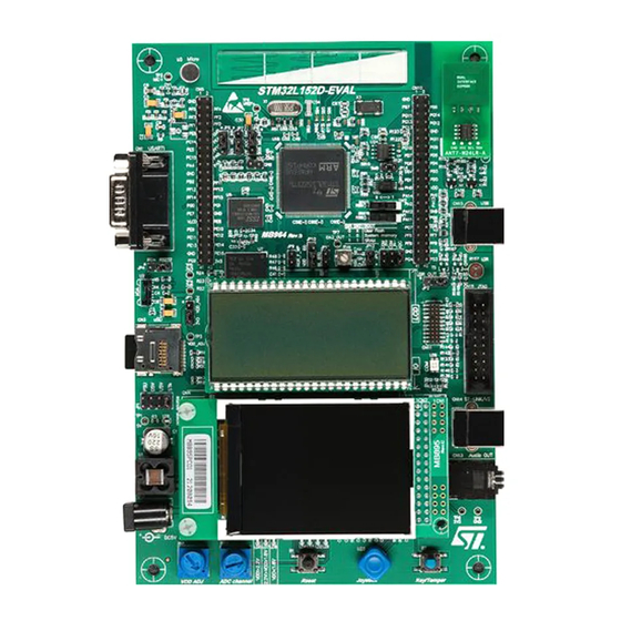
STM32L152-EVAL evaluation board
Introduction
The STM32L152-EVAL evaluation board is a complete demonstration and development
platform for STMicroelectronics' ARM cortex-M3 core-based STM32L152VBT6
microcontroller supporting two I2C, two SPI and three USART channels, 12-bit ADC, 12-bit
DAC, 16 KB internal SRAM and 128 KB Flash, USB FS, LCD controller, touch sensing and
JTAG debugging support.
The full range of hardware features on the board helps you evaluate all peripherals (USB
FS, USART, Audio DAC, microphone ADC, dot-matrix LCD, LCD glass, IrDA, light
TM
dependant resistor (LDR), MicroSD Card
and temperature sensor amongst others) and
develop your own applications. Extension headers make it possible to easily connect a
daughter board or wrapping board for your specific application.
An ST-LINK/V2 is integrated on the board as embedded in-circuit debugger and
programmer for the STM32 MCU.
December 2010
Doc ID 18141 Rev 1
1/44
www.st.com
Downloaded from
Elcodis.com
electronic components distributor
Advertisement
Chapters
Table of Contents

Subscribe to Our Youtube Channel
Related Manuals for ST STM32L152-EVAL


Summary of Contents for ST STM32L152-EVAL
- Page 1 Extension headers make it possible to easily connect a daughter board or wrapping board for your specific application. An ST-LINK/V2 is integrated on the board as embedded in-circuit debugger and programmer for the STM32 MCU. December 2010...
-
Page 2: Table Of Contents
ST-LINK/V2 programming connector CN10 ..... . . 23 ST-LINK/V2 USB type B connector CN11 ......24... - Page 3 UM1018 Contents User USB Type B connector CN1 ......24 Audio jack CN3 ..........24 JTAG connector CN9 .
-
Page 4: Features
For more information and to download the latest version available, please refer to the STM32L152-EVAL demonstration software available on www.st.com. Order code To order the STM32L152VBT6 evaluation board, use the order code STM32L152-EVAL. 4/44 Doc ID 18141 Rev 1 Downloaded from Elcodis.com... -
Page 5: Hardware And Layout
UM1018 Hardware and layout Hardware and layout The STM32L152-EVAL evaluation board is designed around the STM32L152VBT6 microcontroller in a 100-pin TQFP package. Figure 1 illustrates the connections between the STM32L152VBT6 and its peripherals (color LCD, touch sensing button, USB FS connector, temperature sensor, USART, IrDA, audio, MicroSD Card and embedded ST-LINK/V2). - Page 6 Hardware and layout UM1018 Figure 2. STM32L152-EVAL board layout CN6, CN7 Extension header VDD range TS1 & TS2 Touch sensing button LEDs indicator USB FS CN2 UART2 R34 LDR STM32L152VBT6 audio jack CN5 UART3 MicroSD card LCD glass module IrDA...
-
Page 7: Development And Debug Support
CN8 (trace) or CN9 (external JTAG and SWD). Power supply The STM32L152-EVAL is designed to be powered by a 5 V DC power supply and to be protected by PolyZen from a wrong power plug-in event. It is possible to configure the... - Page 8 Table 1. Power related jumpers Jumper Description Jumper setting For power supply from jack (CN12) to the STM32L152-EVAL only, JP12 is set as shown. For power supply from daughterboard connector (CN6) to STM32L152-EVAL only, JP12 is set as shown. JP12...
-
Page 9: Clock Source
PH1 is connected to extension connector CN7 when SB3 is closed. In such case C30 and X2 must be removed. Reset source The reset signal of STM32L152-EVAL evaluation board is low active and the reset sources include: ● Reset button B1 ●... -
Page 10: Boot Option
This configuration is used for boot loader application only. Default setting: Not fitted. LCD glass module An LCD glass module, U20, with 8-digit liquid crystal display is mounted on the STM32L152-EVAL evaluation board. It is connected to the LCD controller of STM32L152VBT6. Table 6. LCD glass related jumpers... -
Page 11: Audio
JP16 Speaker amplifier U27 is disabled when JP16 is closed. The STM32L152-EVAL evaluation board supports USB 2.0 compliant full speed communication via a USB type B connector (CN1). The evaluation board can be powered by this USB connection at 5 V DC with 500 mA current limitation. -
Page 12: Touch Sensing Buttons
Table 5 for Bootloader_BOOT0 settings. 2.10 Touch sensing buttons The STM32L152-EVAL evaluation board supports two touch sensing buttons based on either charge transfer technology (default) or RC charging. RC charging technology can be enabled by modifying the board: Remove R29. -
Page 13: Comparator
(for instance Band gap) in order to test analogue Wakeup feature of the MCU. Figure 3. STM32L152-EVAL comparator features Jumper JP17 allows 3 different usages of the potentiometer as shown in Table Table 10. -
Page 14: Temperature Sensor
Hardware and layout UM1018 Table 10. Comparator and potentiometer related jumpers (continued) Jumper Description Setting PB4 is connected to JTAG connector CN9 (TRST) when JP10 is set as shown (default setting). JP10 PB4 is connected to LDR when JP10 is set as shown. PB5 is connected to I2C_SMB, the interrupt output of temperature sensor U18 when JP11 is closed (default setting). -
Page 15: Display And Input Devices
UM1018 Hardware and layout 2.15 Display and input devices The display devices are: ● 2.4" color TFT LCD, connected to the SPI1 port of the STM32L152VBT6. ● 4 general purpose color LED's (LD 1,2,3,4). LD3 and LD4 are disabled by default; JP18 and JP19 must be closed to enable these two LEDs. -
Page 16: Idd Measurement
The built-in IDD measurement circuit implemented allows the consumption measurement of the STM32L152C6T6 while the MCU is in Run or Low power saving modes. For IDD measurement the circuit below is implemented on STM32L152-EVAL. Figure 4. STM32L152-EVAL IDD measurement circuit... - Page 17 NRST pin (U11 pin 14). The reason for this is that the NRST pin of the STM32L is connected to the ST-LINK MCU T_NRST signal (U23 pin 18), and as the ST-LINK is powered at 3.3 V a leakage current is injected into the STM32L NRST pin when MCU VDD becomes equal to or greater than 3.5 V.
-
Page 18: Ibias Current Measurement Procedure
Hardware and layout UM1018 2.16.3 Ibias current measurement procedure In Low power mode the bias current of operational amplifier input (U10 pin 4) is not negligible compared to IDD current (typical Ibias is ~240 nA). To obtain a reliable MCU IDD measurement it is possible to subtract the bias current from the IDD low power measurement since this current is not sinked by the MCU. -
Page 19: Connectors
UM1018 Connectors Connectors RS-232 connectors (CN2, CN5) Figure 6. RS-232 connector (viewed from front) Table 13. RS-232 connector CN2 with HW flow control and ISP support Pin number Description Pin number Description Bootloader_BOOT0 RS-232_RX (PD6) RS-232_RTS(PD4) RS-232_TX (PD5) RS-232_CTS(PD3)/Bootloader_RESET Table 14. RS-232 connector CN5 Pin number Description... -
Page 20: Power Connector (Cn12)
Connectors UM1018 Power connector (CN12) Your STM32L152-EVAL evaluation board can be powered from a DC 5 V power supply via the external power supply jack (CN12) shown in Figure 7. The central pin of CN12 must be positive. Figure 7. - Page 21 UM1018 Connectors Table 15. Daughterboard extension connector CN6 (continued) How to disconnect with function block on Pin Description Alternative function STM32L152-EVAL board USART2_CTS JP9 open USART2_TX / LED4 JP19 open CS_uSD Remove SD card from CN4 VLCD JTDO / COMP_POT-...
- Page 22 LCD glass_COM3 Remove LCD glass U20 +3V3 Table 16. Daughterboard extension connector CN7 How to disconnect with function block Pin Description Alternative function on STM32L152-EVAL board PD14 LCD glass_SEG34 Remove LCD glass U20 PD12 LCD glass_SEG32 Remove LCD glass U20 PD10...
-
Page 23: St-Link/V2 Programming Connector Cn10
LCD glass_SEG18 Remove LCD glass U20 ST-LINK/V2 programming connector CN10 Connector CN10 is used only for embedded ST-LINK/V2 programming during board manufacture. It is not populated by default and is not for end user usage. Doc ID 18141 Rev 1... -
Page 24: St-Link/V2 Usb Type B Connector Cn11
Connectors UM1018 ST-LINK/V2 USB type B connector CN11 The USB connector, CN11, is used to connect the embedded ST-LINK/V2 to the PC for board debugging. Figure 8. USB type B connector CN11 (viewed from front) Table 17. USB type B connector CN11... -
Page 25: Jtag Connector Cn9
UM1018 Connectors JTAG connector CN9 Figure 10. JTAG debugging connector CN9 (viewed from above PCB) Table 19. JTAG debugging connector CN9 Pin number Description Pin number Description 3.3 V power 3.3 V power PA15 PA13 PA14 RTCK RESET# DBGRQ DBGACK 3.10 Trace debugging connector CN8 This is the same connector type as CN9 (see... -
Page 26: Microsd Card Connector Cn4
Connectors UM1018 Table 20. Trace debugging connector CN8 (continued) Pin number Description Pin number Description TraceD2/PE5 TraceD3/PE6 3.11 MicroSD Card connector CN4 Figure 11. MicroSD Card connector CN4 (viewed from front) Table 21. MicroSD Card connector CN4 Pin number Description Pin number Description MicroSDcard_CLK (PB13) -
Page 27: Bnc Connector Cn13
UM1018 Connectors 3.12 BNC connector CN13 Figure 12. Analog input connector CN13 (viewed from bottom) Table 22. Analog input connector CN13 Pin number Description Pin number Description Analog input PA5 Doc ID 18141 Rev 1 27/44 Downloaded from Elcodis.com electronic components distributor... -
Page 28: Schematics
Schematics UM1018 Schematics The following schematics are listed. ● Figure 13: STM32L152-EVAL on page 29 ● Figure 14: MCU on page 30 ● Figure 15: LCD glass on page 31 ● Figure 16: Audio on page 32 ● Figure 17: Peripherals on page 33 ●... -
Page 29: Figure 13: Stm32L152-Eval
Figure 13. STM32L152-EVAL U_LCD_Glass U_MCU U_Touch Sensing LCD_Glass.SCHDOC MCU.SchDoc Touch Sensing.SchDoc SEG[0..43] SEG[0..43] TS_LOAD TS_LOAD COM[0..3] COM[0..3] TS_SHIELD TS_SHIELD TS_CT TS_CT U_Audio Audio.SchDoc Audio_IN Audio_IN U_Peripherals Audio_OUT Audio_OUT Peripherals.SchDoc U_Extension connector Extension connector.SCHDOC LED4 LED4 RESET# RESET# LED3 LED3 PH[0..2] PH[0..2]... -
Page 30: Figure 14: Mcu
SEG36 SEG39 09.03290.01 SEG38 STM32L152VBT6 100nF 100nF 100nF 100nF 100nF BAT60JFILM SEG[0..43] RESET SEG[0..43] R137 100K 220K [N/A] R138 100nF Bootloader_BOOT0 BAT60JFILM Title: RESET# Bootloader_RESET STM32L152-EVAL MCU Number: MB819 Rev: B.3(PCB.SCH) Date: 10/13/2010 Sheet Downloaded from Elcodis.com electronic components distributor... -
Page 31: Figure 15: Lcd Glass
Figure 15. LCD glass SEG[0..43] COM[0..3] SEG[0..43] COM[0..3] PD878-DP-FH-W-LV-6-RH Title: STM32L152-EVAL LCD Glass Number: MB819 Rev: B.3(PCB.SCH) Date: 10/13/2010 Sheet Downloaded from Elcodis.com electronic components distributor... -
Page 32: Figure 16: Audio
10uF R106 KECG2740TBL MIC_OUT R128 MIC+ TS461CLT R108 Audio_IN 100nF 47pF [N/A] [N/A] R129 R135 100K R101 180pF R107 R100 4.7uF 2.2uF 100K 4.7uF Title: STM32L152-EVAL Audio Number: MB819 Rev: B.3(PCB.SCH) Date: 11/8/2010 Sheet Downloaded from Elcodis.com electronic components distributor... -
Page 33: Figure 17: Peripherals
Vbus JOY_LEFT LEFT USB-typeB connector PE11 R117 I/O2 I/O2 JOY_RIGHT RIGHT R126 JOY_UP USBLC6-2P6 (optional) PA11 USB_DM PA12 MT008-A USB_DP SHELL SHELL Joystick 4.7nF Title: STM32L152-EVAL Peripherals Number: MB819 Rev: B.3(PCB.SCH) Date: 10/13/2010 Sheet Downloaded from Elcodis.com electronic components distributor... -
Page 34: Figure 18: Power
SMAJ5.0A-TR 100nF BNX002-01 VDD_ADJ LD1086D2M VDD_ADJ 124[1%] Vout Power Supply VDD_ADJ [1.65V to 3.6V] 10uF JP12 40.2[1%] U5V_ST_LINK Ground 100nF 3386P-201H[5%] 2K2[1%] Header 4X2 Title: STM32L152-EVAL Power Number: MB819 Rev: B.3(PCB.SCH) Date: 10/13/2010 Sheet Downloaded from Elcodis.com electronic components distributor... -
Page 35: Figure 19: Extension Connector
Header 25X2 Header 25X2 PA[0..15] PA[0..15] PB[0..15] PB[0..15] PC[0..15] PC[0..15] PD[0..15] PD[0..15] PE[0..15] PE[0..15] RESET# RESET# Open by default close to MCU PH[0..2] PH[0..2] Title: STM32L152-EVAL Extension Connector Number: MB819 Rev: B.3(PCB.SCH) Date: 10/13/2010 Sheet Downloaded from Elcodis.com electronic components distributor... -
Page 36: Figure 20: Lcd And Sd Card
VCCA VCCB PE15 SPI1_MOSI_3V3 SPI1_MISO_3V3 SPI1_MOSI PB15 SPI2_MOSI_3V3 SPI2_MOSI RESET +3V3 +3V3 SN74LVC2T45DCUT BSN20 BL_VDD RESET# BL_Control BL_GND BL_GND TFT LCD Do not fit Title: STM32L152-EVAL LCD&SDcard Number: MB819 Rev: B.3(PCB.SCH) Date: 10/13/2010 Sheet Downloaded from Elcodis.com electronic components distributor... -
Page 37: Figure 21: Rs-232 And Irda
SN74LVC2T45DCUT +3V3 100nF USART2_TXD 100nF IrDA_RXD VCCA VCCB +3V3 PC10 USART3_TXD USART3_TX Anode (VCC2) Cathode VCC1 100K SN74LVC2T45DCUT TFDU6300 IrDA 4.7uF 4.7uF 100nF 100nF Title: STM32L152-EVAL RS232&IrDA Number: MB819 Rev: B.3(PCB.SCH) Date: 10/13/2010 Sheet Downloaded from Elcodis.com electronic components distributor... -
Page 38: Figure 22: Idd_Measurement
Figure 22. IDD_Measurement VDD_MCU MAX9938FEUK+ IDD_Measurement SN74LVC1G66DCKT 1K[1%] 1[1%] SN74LVC1G04DCKT IDD_WAKEUP FDC606P FDC606P 100nF PC13 IDD_CNT_EN 74LV4060PW Oscillator frequency 30KHz Title: STM32L152-EVAL IDD_Measurement Number: MB819 Rev: B.3(SCH.PCB) Date: 10/13/2010 Sheet Downloaded from Elcodis.com electronic components distributor... -
Page 39: Figure 23: Temperature Sensor
Figure 23. Temperature sensor +3V3 FDN327N I2C_SDA I2C_SLK I2C_SMB OS/INT 100nF STLM75M2E FDN327N Temperature sensor Title: STM32L152-EVAL TemperatureSensor Number: MB819 Rev: B.3(PCB.SCH) Date: 10/13/2010 Sheet Downloaded from Elcodis.com electronic components distributor... -
Page 40: Figure 24: St-Link
+3V3 T_JTMS TMS/SWDIO T_NRST RESET# T_JRST U5V_ST_LINK TRST 9013 T_JTDI T_JTCK TCK/SWCLK CN11 JTAG R104 USB_DM USB_DP SHELL SHELL USB-typeB connector Title: 1.5K STM32L152-EVAL ST_LINK (JTAG only) Number: MB819 Rev: B.3(PCB.SCH) Date: 10/13/2010 Sheet Downloaded from Elcodis.com electronic components distributor... - Page 41 RESET# D8 D7 [N/A] FTSH-110-01-L-DV JTAG [N/A] R70 0 R65 [N/A] R71 0 R74 [N/A] JTAG connector TRACE_D3 TRACE_D2 TRACE_D1 TRACE_D0 TRACE_CK Trace connector Title: STM32L152-EVAL JTAG&Trace Number: MB819 Rev: B.3(PCB.SCH) Date: 10/13/2010 Sheet Downloaded from Elcodis.com electronic components distributor...
-
Page 42: Figure 26: Touch Sensing
TS_CT Mount only for Charge transfer mode---> <----ESD resistor close to MCU pad <----Touch Sensing diameter 10mm min on active shield diameter 12mm min GRM3195C1H333JA01D TS_PAD TS_PAD Title: STM32L152-EVAL Touch Sensing Number: MB819 Rev: B.3(PCB.SCH) Date: 10/13/2010 Sheet Downloaded from Elcodis.com... -
Page 43: Revision History
UM1018 Revision history Revision history Table 23. Document revision history Date Revision Changes 13-Dec-2010 Initial release. Doc ID 18141 Rev 1 43/44 Downloaded from Elcodis.com electronic components distributor... - Page 44 No license, express or implied, by estoppel or otherwise, to any intellectual property rights is granted under this document. If any part of this document refers to any third party products or services it shall not be deemed a license grant by ST for the use of such third party products or services, or any intellectual property contained therein or considered as a warranty covering the use in any manner whatsoever of such third party products or services or any intellectual property contained therein.
Need help?
Do you have a question about the STM32L152-EVAL and is the answer not in the manual?
Questions and answers