ST STM32L4 User Manual
Discovery kit for iot node, multi-channel communication
Hide thumbs
Also See for STM32L4:
- Manual (213 pages) ,
- User manual (110 pages) ,
- Programming manual (262 pages)
Table of Contents
Advertisement
Quick Links
UM2153
User manual
Discovery kit for IoT node, multi-channel communication
with STM32L4
Introduction
The STM32L4 Discovery kit for the IoT node (B-L475E-IOT01A) allows users to develop
applications with direct connection to cloud servers.
The STM32L4 Discovery kit enables a wide diversity of applications by exploiting low-power
multilink communication (BLE, Sub-GHz), multiway sensing (detection, environmental
®
®
awareness) and Arm
Cortex
-M4 core-based STM32L4 Series features.
Arduino™ Uno V3 and PMOD connectivity provide unlimited expansion capabilities with a
large choice of specialized add-on boards.
The STM32L4 Discovery kit includes an ST-LINK debugger/programmer and comes with
the comprehensive STM32Cube software libraries together with packaged software
®
examples to seamlessly connect to cloud servers. In addition a direct access to the Arm
™
mbed Enabled
on-line resources at http://mbed.org is available.
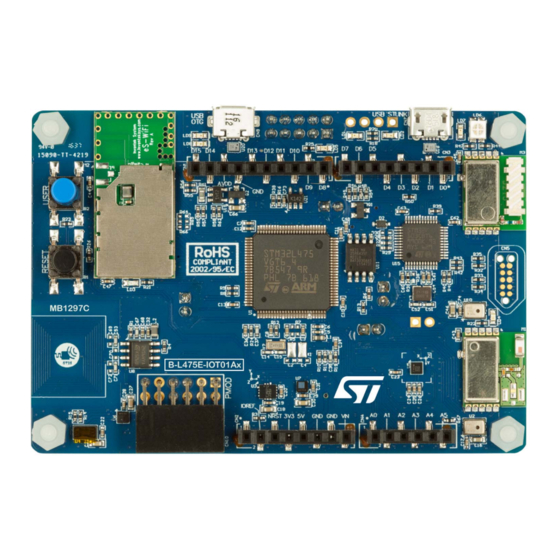
Figure 1. B-L475E-IOT01A Discovery kit
1. Picture is not contractual.
March 2018
UM2153 Rev 4
1/57
www.st.com
1
Advertisement
Table of Contents

Related Manuals for ST STM32L4


Summary of Contents for ST STM32L4
-
Page 1: Figure 1. B-L475E-Iot01A Discovery Kit
Discovery kit for IoT node, multi-channel communication with STM32L4 Introduction The STM32L4 Discovery kit for the IoT node (B-L475E-IOT01A) allows users to develop applications with direct connection to cloud servers. The STM32L4 Discovery kit enables a wide diversity of applications by exploiting low-power multilink communication (BLE, Sub-GHz), multiway sensing (detection, environmental ®... -
Page 2: Table Of Contents
Embedded ST-LINK/V2-1 ........13... - Page 3 TAG connector CN5 ......... 32 ST-LINK/V2-1 USB Micro-B ........33 ST-LINK debug connector CN8 .
- Page 4 Table 11. STM32L4 Discovery kit for IoT node I/O assignment ......37 Table 12.
- Page 5 Figure 4. STM32L4 Discovery kit for IoT node (bottom view) ......11 Figure 5.
-
Page 6: Features
Features UM2153 Features ® ® • Ultra-low-power STM32L4 Series MCUs based on Arm Cortex -M4 core with 1 Mbyte of Flash memory and 128 Kbytes of SRAM, in LQFP100 package • 64-Mbit Quad-SPI (Macronix) Flash memory ® • Bluetooth V4.1 module (SPBTLE-RF) •... -
Page 7: Product Marking
Any consequences deriving from such usage will not be at ST charge. In no event, ST will be liable for any customer usage of these engineering sample tools as reference design or in production. -
Page 8: Ordering Information
Ordering information UM2153 Ordering information To order the B-L475E-IOT01A Discovery kit for IoT node, depending on the frequency of the Sub-GHz module, refer to Table Table 1. Ordering information Order code Sub-GHz operating frequency B-L475E-IOT01A1 915 MHz B-L475E-IOT01A2 868 MHz 8/57 UM2153 Rev 4... -
Page 9: Hardware Layout And Configuration
UM2153 Hardware layout and configuration Hardware layout and configuration The STM32L4 Discovery kit for IoT node is designed around the STM32L475VGT6 (100- pin, LQFP package). The hardware block diagram (see Figure 2) illustrates the connection between the STM32 and peripherals (embedded ST-LINK, Arduino Uno V3 shields, PMOD connector, Quad-SPI Flash memory, USB OTG connectors, digital microphones, various ST-MEMS sensors and the four RF modules (Wi-Fi, Bluetooth, Sub-GHz and NFC)). -
Page 10: Stm32L4 Discovery Kit For Iot Node Layout
STM32L4 Discovery kit for IoT node layout Figure 3. STM32L4 Discovery kit for IoT node (top view) -
Page 11: Figure 4. Stm32L4 Discovery Kit For Iot Node (Bottom View)
Figure 4. STM32L4 Discovery kit for IoT node (bottom view) -
Page 12: Stm32L4 Discovery Kit For Iot Node Mechanical Drawing
STM32L4 Discovery kit for IoT node mechanical drawing Figure 5. STM32L4 Discovery kit for IoT node mechanical drawing 1. Plastic Spacer Height = 14mm, Overall Height = 26mm +/- 1mm. -
Page 13: Embedded St-Link/V2-1
In case the STM32L4 Discovery kit for IoT node is connected to the PC before the driver is installed, some STM32L4 Discovery kit interfaces may be declared as “unknown” in the PC device manager. In this case the user must install the driver files, and update the driver of... -
Page 14: St-Link/V2-1 Firmware Upgrade
Power supply The STM32L4 Discovery kit for IoT node is designed to be powered by 5 V DC power supply. It is possible to configure the STM32L4 Discovery kit to use any of the following five sources for the power supply: 5V_ST_LINK, 5V_ARD, 5V_USB_FS, 5V_VBAT and 5V_USB_CHARGER. -
Page 15: Figure 7. Jp4: 5V_St_Link Selection
UM2153 Hardware layout and configuration Figure 7. JP4: 5V_ST_LINK selection • 5V_ARD (see Figure 8) is the 7 to 12 V DC power from Arduino CN2 pin 8 (named VIN on Arduino connector silkscreen). In this case, jumper of JP4 should be on pins 3 and 4 to select the 5V_ARD power source on silkscreen of JP4. -
Page 16: Figure 9. Jp4: 5V_Usb_Fs
ST-LINK (CN7). To select the 5V_USB_CHARGER power source on silkscreen of JP4, the jumper of JP4 should be on pins 9 and 10. In this case, if the STM32L4 Discovery kit for IoT node is powered by an external USB charger then the debug is not available. If the PC is connected instead of the charger, the limitation is no longer effective and the PC could be damaged. -
Page 17: Figure 11. Jp4: 5V_Usb_Charger Selection
Do not connect the PC to the ST-LINK (CN7) when R30 is soldered. The PC may be damaged or the board may not be powered correctly. The green LED LD5 is lit when the STM32L4 Discovery kit for IoT node is powered by the 5 V correctly. -
Page 18: Figure 12. Power Tree
Hardware layout and configuration UM2153 Figure 12. Power tree 18/57 UM2153 Rev 4... -
Page 19: Programming/Debugging When The Power Supply Is Not From
X2 which is the 32.768 KHz crystal for the STM32L475VG embedded RTC • X3 which is the 8 MHz clock from ST-LINK MCU for the STM32L475VG microcontroller. Reset sources The reset signal of the STM32L4 Discovery kit is active low and the reset sources includes: • A reset button B1 •... -
Page 20: Quad-Spi Nor Flash Memory
0 ohm resistor (0402 size) at R5 position • 0 ohm resistor (0402 size) at R7 position The STM32L4 Discovery kit can be powered by the USB connectors at 5 V DC with 500 mA current limitation. A USB power switch (IC19) is also connected on V and provides power to CN9. -
Page 21: Sub-Ghz Low-Power-Programmable Rf Module
Figure 13. SPBTLE-RF module The main features of the ST SPBTLE-RF module are listed below. • Bluetooth V4.1 compliant (supports master and slave modes, multiple roles supported simultaneously •... -
Page 22: Wi-Fi Module Inventek Ism43362-M3G-L44 (802.11 B/G/N)
7.11.3 Wi-Fi module Inventek ISM43362-M3G-L44 (802.11 b/g/n) The Inventek ISM43362-M3G-L44 module (M2) is implemented on top side of the STM32L4 Discovery kit for IoT node board. This module is an embedded (eS-WiFi) wireless Internet Connectivity device. The Wi-Fi module hardware consists of an Arm® Cortex® -M3 STM32 host processor, an integrated antenna (or optional external antenna) and a Broadcom Wi-Fi device. -
Page 23: Dynamic Nfc Tag Based On M24Sr With Its Printed Nfc Antenna
Supports Broadcom WICED SDK ® ® • CPU Arm Cortex -M3 32-bit RISC core from ST Microelectronics • IEEE 802.11n D7.0 -OFDM-72.2 Mbps -single stream w/20 MHz, Short GI • IEEE 802.11g (OFDM 54 Mbps) • IEEE 802.11b (DSSS 11 Mbps) •... -
Page 24: Stmicroelectronics Sensors
7-Byte unique identifier (UID) • 128-bit password protection 7.12 STMicroelectronics sensors Several STMicroelectronics sensors are available on the STM32L4 Discovery kit for IoT node board, they are listed below: • 2 on-board ST-MEMS audio sensor omnidirectional digital microphones (MP34DT01) •... -
Page 25: Capacitive Digital Sensor For Relative Humidity And Temperature (Hts221)
UM2153 Hardware layout and configuration On the STM32L4 Discovery kit for IoT node, there are two MP34DT01 microphones: one with LR pulled to V and the second with LR pulled low. DFSDM1_CKOUT and DFSDM1_DATIN2 are connected for both. In addition, both microphones are spaced at 21 mm apart for the beamforming algorithm to work. -
Page 26: Accelerometer And 3D Gyroscope (Lsm6Dsl)
The LIS3MDL includes an I C serial bus interface, that supports standard and fast mode (100 kHz and 400 kHz), and an SPI serial standard interface. On the STM32L4 Discovery kit IoT node, the I2C2 bus from STM32L475VG is used. -
Page 27: Time-Of-Flight And Gesture Detection Sensor (Vl53L0X)
The VL53L0X integrates a leading-edge SPAD array (Single Photon Avalanche Diodes) and ™ embeds an ST second generation FlightSense patented technology. The VL53L0X 940 nm VCSEL emitter (Vertical Cavity Surface-Emitting Laser), is totally invisible to the human eye, coupled with internal physical infrared filters, it enables longer ranging distance, higher immunity to ambient light and better robustness to cover-glass optical cross-talk. -
Page 28: Stsafe-A 100
UM2153 STMicroelectronics recommended device settings are used and the operating conditions, specified in the STM32L4 datasheets, are respected. The laser output power must not be increased by any means and no optics should be used with the intention of focusing the laser beam. -
Page 29: I2C Addresses Of Modules Used On Mb1297
PC9, Wi-Fi activity blue LED4 (BLE) PC9, Bluetooth activity green 5V Power 5 V available Bicolor (red and green) ST-LINK COM green when communication Fault Power Current upper than 750 mA OCRCR green 5 V USB available 7.15 I2C addresses of modules used on MB1297... -
Page 30: Connectors
Arduino Uno V3 connectors CN1, CN2, CN3 and CN4 are female connectors (SMD component devices) compatible with Arduino Uno V3. Most shields designed for Arduino can fit to the STM32L4 Discovery kit for IoT node. Example connector references (see... -
Page 31: Table 4. Arduino Connector Pinout
UM2153 Connectors Table 4. Arduino connector pinout STM32 Connector Pin name Signal name Function number IOREF 3.3 V reference NRST STM_NRST NRST Reset 3.3 V 3.3 V input/output Power input ARD.A0-ADC ARD.A1-ADC ARD.A2-ADC ARD.A3-ADC ARD.A4-ADC ADC / I2C3_SDA ARD.A5-ADC ADC / I2C3_SCL SCL/D15 ARD.D15-I2C1_SCL I2C1_SCL... -
Page 32: Tag Connector Cn5
Connectors UM2153 TAG connector CN5 The TAG connector is implemented on the STM32L4 Discovery kit for IoT node. The TAG connector is a 10-pin footprint supporting SWD mode, which is shared with the same signals as for the ST-LINK. The TC2050-IDC-NL cable is used to link ST-LINK and TAG connector on the STM32L4 Discovery kit for IoT node, so that the STM32L4 can be easily programmed and debugged without any extra accessory. -
Page 33: St-Link/V2-1 Usb Micro-B
UM2153 Connectors ST-LINK/V2-1 USB Micro-B The USB connector is used to connect the embedded ST-LINK/V2-1 to the PC to program and debug the STM32L475VGT6 microcontroller. Figure 20. USB Micro-B connector CN7 (front view) Table 6. USB Micro-B connector STM32L4 Connector... -
Page 34: Usb Otg Fs Micro-Ab
USB Power enable PMOD connector CN10 On STM32L4 Discovery kit for IoT node, the PMOD connector provides flexibility in small form factor application. Based on PMOD Digilent standard popular in connectivity, the PMOD connector is implemented in type 2A and 4A. -
Page 35: Table 10. Pmod Solder Bridge Configuration
Table 10. PMOD solder bridge configuration Alternate configuration (UART) Standard configuration (SPI) STM32L4 Solder bridge STM32L4 Solder bridge PMOD pin Pin name Pin name STM32L4 pin configuration configuration number name SB14 open; PMOD-UART2_ SB14 close; PMOD-UART2_ PMOD-IRQ_EXTI2 SB19 close CTS/SPI2_MISO... -
Page 36: Jumper Jp5 For Idd Measurements
Connectors UM2153 Jumper JP5 for IDD measurements The STM32 current measurement can be done on JP5. By default a jumper is placed on JP5. For current measurement configuration, the jumper on JP5 should be removed and an amp-meters should be placed on JP5. 36/57 UM2153 Rev 4... -
Page 37: Appendix Astm32L4 Discovery Kit For Iot Node I/O Assignment
UM2153 STM32L4 Discovery kit for IoT node I/O assignment Appendix A STM32L4 Discovery kit for IoT node I/O assignment Table 11. STM32L4 Discovery kit for IoT node I/O assignment Pin Name Feature / Comment Signal or Label GPIO_Output M24SR64-Y-RF_DISABLE GPIO_EXTI3... - Page 38 STM32L4 Discovery kit for IoT node I/O assignment UM2153 Table 11. STM32L4 Discovery kit for IoT node I/O assignment (continued) Pin Name Feature / Comment Signal or Label SPI1_MOSI ARD.D11-SPI1_MOSI/PWM ADC1_IN13 ARD.A1-ADC ADC1_IN14 ARD.A0-ADC TIM3_CH3 ARD.D3-PWM/INT1_EXTI0 TIM3_CH4 ARD.D6-PWM GPIO_Output ARD.D8...
- Page 39 UM2153 STM32L4 Discovery kit for IoT node I/O assignment Table 11. STM32L4 Discovery kit for IoT node I/O assignment (continued) Pin Name Feature / Comment Signal or Label GPIO_EXTI9 LED3 (WIFI) & LED4 (BLE) GPIO_Output SPBTLE-RF-RST USB_OTG USB_OTG_FS_VBUS PA10 USB_OTG...
- Page 40 STM32L4 Discovery kit for IoT node I/O assignment UM2153 Table 11. STM32L4 Discovery kit for IoT node I/O assignment (continued) Pin Name Feature / Comment Signal or Label 3.3 V DD_MCU 40/57 UM2153 Rev 4...
-
Page 41: Appendix B Schematics
UM2153 Schematics Appendix B Schematics This section provides the design schematics for the STM32L4 Discovery kit for IoT node: • Overall schematics for the B-L475E-IOT01A, see Figure 22 • STM32L475VG MCU, see Figure 23 Figure 24 • USB OTG FS, see Figure 25 •... -
Page 42: Figure 22. Stm32L4 Discovery Kit For Iot Node (Top)
Figure 22. STM32L4 Discovery kit for IoT node (top) RF Modules Page 5/11 MB1297_RF_Module.SchDoc MCU1 Page 2/11 Arduino Connectors Page 9/11 MB1297_MCU1.SchDoc MB1297_Arduino.SchDoc INTERNAL-SPI3_SCK INTERNAL-SPI3_SCK ARD.D15-I2C1_SCL ARD.D15-I2C1_SCL INTERNAL-SPI3_MOSI INTERNAL-SPI3_MOSI ARD.D14-I2C1_SDA ARD.D14-I2C1_SDA INTERNAL-SPI3_MISO INTERNAL-SPI3_MISO ARD.D13-SPI1_SCK/LED1 ARD.D13-SPI1_SCK/LED1 SPSGRF-915-SPI3_CSN SPSGRF-915-SPI3_CSN ARD.D12-SPI1_MISO ARD.D12-SPI1_MISO SPSGRF-915-GPIO3_EXTI5 SPSGRF-915-GPIO3_EXTI5 ARD.D11-SPI1_MOSI/PWM... -
Page 43: Figure 23. Stm32L475Vg Microcontroller
Figure 23. STM32L475VG microcontroller ARD.D1-UART4_TX PA0/WKUP1 ARD.D3-PWM/INT1_EXTI0 ARD.D0-UART4_RX ARD.D6-PWM ARD.D10-SPI_SSN/PWM ARD.D8 ARD.D4 PB3/SWO SYS_JTDO-SWO ARD.D7 ARD.D5-PWM ARD.D13-SPI1_SCK/LED1 SPSGRF-915-SPI3_CSN ARD.D12-SPI1_MISO ST-LINK-UART1_TX ARD.D11-SPI1_MOSI/PWM ST-LINK-UART1_RX SPBTLE-RF-RST ARD.D15-I2C1_SCL USB_OTG_FS_VBUS ARD.D14-I2C1_SDA USB_OTG_FS_ID PA10 PB10 INTERNAL-I2C2_SCL USB_N USB_OTG_FS_DM PA11 PB11 INTERNAL-I2C2_SDA USB_P USB_OTG_FS_DP PA12 PB12 ISM43362-BOOT0... -
Page 44: Figure 24. Stm32L475Vg Microcontroller
Figure 24. STM32L475VG microcontroller STM_NRST 100nF Not Fitted (8.2pF) Not Fitted (0R) Not Fitted (NX3225GD-8.00M) PH0/PF0-OSC_IN NRST PH1/PF1-OSC_OUT BOOT0 VDD_MCU Open Not Fitted (0R) Not Fitted (8.2pF) VDDA SB13 VDDA VSSA Close VDD_MCU VREF+ VREF- FCM1608KF-601T03 VBAT VDDUSB VDD_MCU 100nF 100nF Close VBAT... -
Page 45: Figure 25. Usb Otg Fs
Figure 25. USB OTG FS VBUS OK LED VBUS OVRCR LED GREEN 330R BSR14 100K 5V_USB_FS USB_OTG_FS_OVRCR_EXTI3 FAULT VBUS USB_OTG_FS_PWR_EN STMPS2141STR 4.7uF Shield Shield Shield Shield 475900001 USB_OTG_FS_VBUS USB_N USB_OTG_FS_DM USB_P USB_OTG_FS_DP USB_OTG_FS_ID Vbus D+out D+in D-out D-in EMIF02-USB03F2 ESD PROTECTION SHOULD BE CLOSE TO THE CONNECTOR Designed by DiZiC Title: USB_OTG_FS... -
Page 46: Figure 26. Rf Module
Figure 26. RF module INTERNAL-SPI3_SCK SPI_SCLK SPI_SCLK Vi V V n INTERNAL-SPI3_MISO SPI_MISO SPI_MISO 100nF INTERNAL-SPI3_MOSI SPI_MOSI SPI_MOSI SPBTLE-RF-SPI3_CSN SPI_CS SPI_CS ANA_TEST 0 ANA_TEST 0 SPBTLE-RF-IRQ_EXTI6 SPI_IRQ SPI_IRQ GPIO2 GPIO2 EXT_LPCLK EXT_LPCLK ISM43362-M3G-L44 SPBTLE-RF-RST BT_RESET BT_RESET BT Module 3V3_WIFI RSTN BOOT0 2.2uF 100nF... -
Page 47: Figure 27. St-Mems Sensors
Figure 27. ST-MEMS sensors Microphone MEMS DFSDM1_CKOUT DFSDM1_DATIN2 DOUT 10uF MP34DT01-M INTERNAL-I2C2_SCL Microphone MEMS INTERNAL-I2C2_SDA VDDIO SDO/SA0 DOUT 4.7uF 100nF 100nF 100nF 10uF MP34DT01-M LSM6DSL_INT1_EXTI11 INT1 INT2 LSM6DSL Read=11010101 (D5h) Write=11010100 (D4h) AVDD_VCSEL INTERNAL-I2C2_SCL AVDD INTERNAL-I2C2_SDA AVSS_VCSEL 4.7uF 100nF INTERNAL-I2C2_SCL... -
Page 48: Figure 28. Nfc And Stsafe Part
M24SR64-Y-GPO M24SR64-Y-RF_DISABLE RFDIS M24SR64-Y 10pF Not Fitted Read=10101101(ADh) Write=10101100(ACh) 10pF Not Fitted Not Fitted INTERNAL-I2C2_SCL INTERNAL-I2C2_SDA 100nF STSAFE-A100-RESET /RESET STSAFE-A100 (Not Fitted) Read=01000001(41h) Write=01000000(40h) Designed by DiZiC Title: NFC & ST-SAFE Part Project: Size: Reference: MB1297 Revision: Date: 12/03/2017 Sheet:... -
Page 49: Figure 29. Power Supply
Figure 29. Power supply 5V PWR SELECTION FROM EXTERNAL SOURCES 5V_ST_LINK 5V_ARD USB_OTG_FS Page4/11 STLINK_V2-1 Page11/11 330R 5V_USB_FS GREEN 5V_VBAT Cannot open HEADER_2X5 file C:\Data 5V_USB_CHARGER SHUNT_BK GND PROBE Cannot Cannot open open file file C:\Data C:\Data SHUNT_BK SHUNT_BK MEMS Page6/11 5V INPUT PWR FROM ARDUINO 5V / 800mA POWER SUPPLY Page8/11... -
Page 50: Figure 30. Arduino Uno V3 Connector
Figure 30. Arduino Uno V3 connector ARDUINO UNO connector VDDA SCL/D15 ARD.D15-I2C1_SCL R3 1k SDA/D14 ARD.D14-I2C1_SDA AVDD 5V_ARD IOREF NRST SCK/D13 STM_NRST ARD.D13-SPI1_SCK/LED1 MISO/D12 ARD.D12-SPI1_MISO PWM/MOSI/D11 ARD.D11-SPI1_MOSI/PWM 100nF PWM/CS/D10 ARD.D10-SPI_SSN/PWM PWM/D9 ARD.D9-PWM WARNING voltage applied to VIN <11.5V ARD.D8 Header 8X1_Female_SMD Header 10X1_Female_SMD ARD.D7 PWM/D6... -
Page 51: Figure 31. Peripherals
Figure 31. Peripherals USER & WAKE-UP Button RESET BUTTON 100K Close Close STM_NRST BUTTON_EXTI13 100nF 10pF 100nF 10pF SW-PUSH-CMS_BLACK SW-PUSH-CMS_BLUE 100nF should be place close to the MCU 100nF should be place close to the MCU 10pF and 1K should be place close to the button 10pF and 1K should be place close to the button USER LED The 2 LEDs are top side... -
Page 52: Figure 32. St-Link/V2-1 With Support Of Swd Only
Figure 32. ST-LINK/V2-1 with support of SWD only Close T_JTMS ST-LINK MCU SYS_JTMS-SWDIO Close BAT60JFILM T_JTCK SYS_JTCK-SWCLK Close T_SWO SYS_JTDO-SWO Board Ident: PC13=0 100K Not Fitted (0R) 3V3_ST_LINK 3V3_ST_LINK Close T_NRST STM_NRST USB_RENUMn STM_JTCK Not Fitted (10K) STM32F103CBT6 3V3_ST_LINK 3V3_ST_LINK... -
Page 53: Appendix C Board Revision History And Limitations
Two pcb changes compared to the MB1297 C-01 pcb: MB1297 D-01 – The reset connexion between STM32L4 and the ST-LINK MCU (STM32F103) is implemented of the MB1297 rev D – The pcb below the Wi-Fi antenna has been removed to have more... -
Page 54: Appendix D Federal Communications Commission (Fcc)
Federal Communications Commission (FCC) and Industry Canada (IC) Compliance UM2153 Appendix D Federal Communications Commission (FCC) and Industry Canada (IC) Compliance Applicable for IoT node Discovery kit products with order code B-L475E-IOT01A1 (containing SPSGRF-915 module). FCC Compliance Statement Contains FCC ID: O7P-362 Contains FCC ID: S9NSPBTLERF Contains FCC ID: S9NSPSGRF D.1.1... -
Page 55: Compliance Statement
UM2153 Federal Communications Commission (FCC) and Industry Canada (IC) Compliance Contains/Contient IC: 8976C-SPSGRF 8.8.1 Compliance Statement Industry Canada ICES-003 Compliance Label: CAN ICES-3 (B)/NMB-3(B) This device complies with Industry Canada’s licence-exempt RSSs. Operation is subject to the following two conditions: This device may not cause interference;... -
Page 56: Revision History
Revision history UM2153 Revision history Table 13. Document revision history Date Revision Changes 31-Mar-2017 Initial version. Updated Section 7.12.6: Time-of-Flight and gesture detection 14-Apr-2017 sensor (VL53L0X) to add Class 1 laser information. Updated: Section 7.11.3: Wi-Fi module Inventek ISM43362-M3G- 28-Jun-2017 L44 (802.11 b/g/n) Section Appendix B: Schematics to reflect... - Page 57 ST products and/or to this document at any time without notice. Purchasers should obtain the latest relevant information on ST products before placing orders. ST products are sold pursuant to ST’s terms and conditions of sale in place at the time of order acknowledgement.
Need help?
Do you have a question about the STM32L4 and is the answer not in the manual?
Questions and answers