Table of Contents
Advertisement
Quick Links
UM1079
User manual
Discovery kits with STM32L152RCT6
and STM32L152RBT6 MCUs
Introduction
The STM32L152RCT6 Discovery kit (32L152CDISCOVERY) and the STM32L152RBT6
(STM32L-DISCOVERY) allow to develop applications based on the STM32L1 Series and to
benefit from the ultra-low-power features of these microcontollers.
The 32L152CDISCOVERY is based on an STM32L152RCT6 (256 Kbytes of Flash
memory). The STM32L-DISCOVERY is based on an STM32L152RBT6 (128 Kbytes of
Flash memory).
These discovery kits include the ST-LINK/V2 in-circuit debugger, one LCD (24 segments, 4
commons), four LEDs, two pushbuttons, one linear touch sensor and four touchkeys.
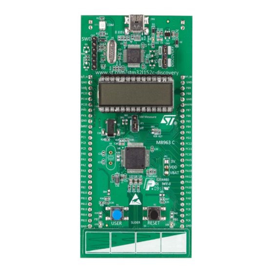
Figure 1. 32L152CDISCOVERY board
1. Picture is not contractual.
January 2017
DocID018789 Rev 4
1/38
www.st.com
1
Arrow.com.
Downloaded from
Advertisement
Table of Contents

Related Manuals for ST STM32L152RCT6 Discovery kit


Summary of Contents for ST STM32L152RCT6 Discovery kit
-
Page 1: Figure 1. 32L152Cdiscovery Board
The STM32L-DISCOVERY is based on an STM32L152RBT6 (128 Kbytes of Flash memory). These discovery kits include the ST-LINK/V2 in-circuit debugger, one LCD (24 segments, 4 commons), four LEDs, two pushbuttons, one linear touch sensor and four touchkeys. Figure 1. 32L152CDISCOVERY board 1. -
Page 2: Table Of Contents
Embedded ST-LINK/V2 ........ - Page 3 UM1079 Contents Revision history ......... . . 37 DocID018789 Rev 4 3/38 Arrow.com.
- Page 4 List of tables UM1079 List of tables Table 1. Ordering information ............6 Table 2.
- Page 5 ST-LINK/V2 (SWD only) ........
-
Page 6: Ordering Information
16 Kbyte RAM, 4 Kbyte data EEPROM). Quick start Before using the discovery kit, please accept the Evaluation product license agreement available on the 32L152CDISCOVERY page of the www.st.com/mcu web site. Getting started The following sequence allows to configure the 32L152CDISCOVERY and to launch the discovery application: •... -
Page 7: System Requirements
RTC ON STM32L152RCT6 consumption measured in Stop mode, RTC OFF STM32L152RCT6 consumption measured in Standby mode Please refer to the www.st.com/mcu web site for more details on the discovery project and the STM32L152RCT6 features. System requirements • Windows PC (XP, Vista, 7) •... -
Page 8: Demonstration Software
An STM32L152RCT6 microcontroller (256 Kbyte Flash memory, 32 Kbyte RAM, 8 Kbyte data EEPROM) in a 64-pin LQFP package • On-board ST-LINK/V2 with selection mode switch to use the kit as a standalone ST-LINK/V2 (with SWD connector for programming and debugging) •... -
Page 9: Hardware And Layout
The 32L152CDISCOVERY is designed around one STM32L152RCT6 packaged in an LQFP64. Figure 2 illustrates the connections between the STM32L152RCT6 microcontroller and its peripherals (ST-LINK/V2, pushbuttons, LEDs, LCD, linear touch sensor, touchkeys, and connectors). These connections are the same for the STM32L-DISCOVERY. Figure 2. Hardware block diagram Figure 3 Figure 4 allow to locate these features on the board. -
Page 10: Figure 3. Top Layout
Hardware and layout UM1079 Figure 3. Top layout 1. Pin 1 of CN1, CN2, P1 and P2 connectors are identified by a square. 10/38 DocID018789 Rev 4 Arrow.com. Arrow.com. Arrow.com. Arrow.com. Arrow.com. Arrow.com. Arrow.com. Arrow.com. Arrow.com. Arrow.com. Downloaded from Downloaded from Downloaded from Downloaded from Downloaded from... -
Page 11: Stm32L152Rct6 Microcontroller
UM1079 Hardware and layout Figure 4. Bottom layout 1. Pin 1 of CN1, CN2, P1 and P2 connectors are identified by a square. STM32L152RCT6 microcontroller The STM32L152RCT6 features 256 Kbytes of Flash memory, 32 Kbytes of RAM and 8 Kbytes data of EEPROM. This microcontroller embeds RTC, LCD, timers, USART, I2C, SPI, ADC, DAC, and comparators. -
Page 12: Figure 5. Stm32L152Rct6 Package
• Analog functional down to 1.8 V, and programming down to 1.65 V • Full functionality over the complete V range For more information, refer to STM32L152RCT6 datasheet available on ST website. 12/38 DocID018789 Rev 4 Arrow.com. Arrow.com. Arrow.com. -
Page 13: Figure 6. Stm32L152Rct6 Block Diagram
UM1079 Hardware and layout Figure 6. STM32L152RCT6 block diagram DocID018789 Rev 4 13/38 Arrow.com. Arrow.com. Arrow.com. Arrow.com. Arrow.com. Arrow.com. Arrow.com. Arrow.com. Arrow.com. Arrow.com. Arrow.com. Arrow.com. Arrow.com. Downloaded from Downloaded from Downloaded from Downloaded from Downloaded from Downloaded from Downloaded from Downloaded from Downloaded from Downloaded from... -
Page 14: Embedded St-Link/V2
Program/debug an MCU in an external application board using a cable connected to SWD connector CN2 The embedded ST-LINK/V2 supports only SWD for STM32 devices. For information about debugging and programming features, refer to the user manual ST-LINK/V2 in-circuit debugger/programmer for STM8 and STM32 (UM1075). -
Page 15: Using The St-Link/V2 To Program/Debug An External Application
Figure 8. 32L152CDISCOVERY connections 4.2.2 Using the ST-LINK/V2 to program/debug an external application The ST-LINK/V2 allows also to program an STM32 device on an external application. Figure 9 shows how to remove the 2 jumpers from CN3 and to connect the external... -
Page 16: Power Supply And Power Selection
Hardware and layout UM1079 Figure 9. ST-Link connections Power supply and power selection The power supply is provided either by the host computer through the USB cable, or by an external 5 V or 3.3 V power supply. The D1 and D2 protection diodes allow to use the EXT_5V and EXT_3V pins independently... -
Page 17: Leds
LEDs • LD1 COM: LD1 default status is red. LD1 turns to green to indicate that communications are in progress between the computer and the ST-LINK/V2. • LD2 PWR: red LED indicates that the board is powered. • User LD3: user green LED connected to the I/O PB7 of the STM32L152RCT6. -
Page 18: Built-In Idd Measurement Circuit
• For more detail concerning touch sensing application design and layout, refer to Guidelines for designing touch sensing applications with surface sensors (AN4312). • STM32 touch sensing library available from www.st.com/mcu Built-in I measurement circuit The 32L152CDISCOVERY built-in I measurement circuit allows to measure the consumption of the STM32L152RCT6 and to display the value on the LCD glass while the MCU is in Run or Low-power modes. -
Page 19: High Idd Range Mode
UM1079 Hardware and layout Figure 10. I measurement circuit 4.7.1 High I range mode In high I range mode, the I current is measured using the operational amplifier MAX9938FEUK+ (U5) connected to the 2 Ω shunt resistor (R21). In this case IDD_CNT_EN remains high during the measurement. -
Page 20: Ibias Current Measurement Procedure
Hardware and layout UM1079 The Q13 output of the counter allows connecting the 1 KW resistor when the current I becomes very low. Figure 11 shows how the counter and the FET transistor 1 of U20 ensure that, 150 ms after IDD_CNT_EN falling edge, the shunt resistor R22 is connected between VDD_MCU and the power supply to reduce the measurement range to 60 μA for the full scale. -
Page 21: Solder Bridges
UM1079 Hardware and layout Solder bridges Table 6. Solder bridges Bridge State Description PH0, PH1 are connected to P1 (X3, C21, C22, R30 must not be fitted). SB18,20 X3, C21, C22 and R30 provide a clock as shown in Section 7: (X3 crystal) Electrical schematics. - Page 22 Hardware and layout UM1079 Table 6. Solder bridges (continued) Bridge State Description The BOOT0 signal of the STM32L152RCT6 is held low through a 510 Ω pull-down resistor. SB3 (BOOT0) The BOOT0 signal of the STM32L152RCT6 is held high through a 10 KΩ pull-up resistor. The BOOT1 signal of the STM32L152RCT6 is held high through a 10 KΩ...
-
Page 23: Lcd (24 Segments, 4 Commons)
UM1079 Hardware and layout LCD (24 segments, 4 commons) This LCD allows the STM32L152RCT6 to display any information on six 14-segment digits and 4 bars, using all COMs. (See the LCD segment mapping in Figure 17 and pin connections in Table Note: This LCD also supports six 8-segment digits by only using COM0 and COM1. -
Page 24: Table 7. Lcd Connections
Hardware and layout UM1079 Table 7. LCD connections STM32L152RCT6 GPIO Name COM3 COM2 COM1 COM0 Name LCDSEG0 1COLON LCDSEG1 LCDSEG2 2COLON LCDSEG3 LCDSEG4 3COLON LCDSEG5 PB10 LCDSEG6 PB11 4COLON LCDSEG7 PB12 LCDSEG8 PB13 BAR2 BAR3 LCDSEG9 PB14 LCDSEG10 PB15 BAR0 BAR1 LCDSEG11 COM3... -
Page 25: Extension Connectors
UM1079 Extension connectors Extension connectors The male headers P1 and P2 can connect the 32L152CDISCOVERY to a standard prototyping/wrapping board. The STM32L152RCT6 GPIOs are available on these connectors. P1 and P2 can also be probed by an oscilloscope, a logical analyzer or a voltmeter. -
Page 26: Table 8. Mcu Pin Description Versus Board Function
Extension connectors UM1079 Table 8. MCU pin description versus board function (continued) MCU pin Board function Linear Push Main Alternate Free Touch butt LED SWD OSC P1 P2 function functions glass supp Sensor SPI1_SCK/ADC_IN 5/ DAC_OUT2/ TIM2_CH1_ETR/C OMP1_INP SPI1_MISO/ADC_I TIM3_CH1/TIM1_B KIN/ LCD_SEG3/TIM10 _CH1/... - Page 27 UM1079 Extension connectors Table 8. MCU pin description versus board function (continued) MCU pin Board function Linear Push Main Alternate Free Touch butt LED SWD OSC P1 P2 function functions glass supp Sensor ADC_IN9/TIM3_CH LCD_SEG6/COMP 1_INP/ VREF_OUT PB2/BO TIM2_CH2/PB3/TR ACESWO/SPI1_S JTDO CK/COMP2_INM/L CD_SEG7...
-
Page 28: Figure 17. Lcd
Extension connectors UM1079 Table 8. MCU pin description versus board function (continued) MCU pin Board function Linear Push Main Alternate Free Touch butt LED SWD OSC P1 P2 function functions glass supp Sensor SPI2_NSS/I2C2_S MBA/ USART3_CK/LCD_ PB12 SEG12/ADC_IN18/ COMP1_INP/ TIM10_CH1 SPI2_SCK/USART 3_CTS/ LCD_SEG13/ADC_... - Page 29 UM1079 Extension connectors Table 8. MCU pin description versus board function (continued) MCU pin Board function Linear Push Main Alternate Free Touch butt LED SWD OSC P1 P2 function functions glass supp Sensor TIM3_CH1/LCD_S EG24 TIM3_CH2/LCD_S EG25 TIM3_CH3/LCD_S EG26 TIM3_CH4/LCD_S EG27 USART3_TX/LCD_ PC10...
-
Page 30: Mechanical Drawing
Mechanical drawing UM1079 Mechanical drawing Figure 13. Mechanical drawing 30/38 DocID018789 Rev 4 Arrow.com. Arrow.com. Arrow.com. Arrow.com. Arrow.com. Arrow.com. Arrow.com. Arrow.com. Arrow.com. Arrow.com. Arrow.com. Arrow.com. Arrow.com. Arrow.com. Arrow.com. Arrow.com. Arrow.com. Arrow.com. Arrow.com. Arrow.com. Arrow.com. Arrow.com. Arrow.com. Arrow.com. Arrow.com. Arrow.com. Arrow.com. Arrow.com. -
Page 31: Electrical Schematics
UM1079 Electrical schematics DocID018789 Rev 4 31/38 Arrow.com. Arrow.com. Arrow.com. Arrow.com. Arrow.com. Arrow.com. Arrow.com. Arrow.com. Arrow.com. Arrow.com. Arrow.com. Arrow.com. Arrow.com. Arrow.com. Arrow.com. Arrow.com. Arrow.com. Arrow.com. Arrow.com. Arrow.com. Arrow.com. Arrow.com. Arrow.com. Arrow.com. Arrow.com. Arrow.com. Arrow.com. Arrow.com. Arrow.com. Arrow.com. Arrow.com. Downloaded from Downloaded from Downloaded from Downloaded from... -
Page 32: Figure 15. St-Link/V2 (Swd Only)
Electrical schematics UM1079 32/38 DocID018789 Rev 4 Arrow.com. Arrow.com. Arrow.com. Arrow.com. Arrow.com. Arrow.com. Arrow.com. Arrow.com. Arrow.com. Arrow.com. Arrow.com. Arrow.com. Arrow.com. Arrow.com. Arrow.com. Arrow.com. Arrow.com. Arrow.com. Arrow.com. Arrow.com. Arrow.com. Arrow.com. Arrow.com. Arrow.com. Arrow.com. Arrow.com. Arrow.com. Arrow.com. Arrow.com. Arrow.com. Arrow.com. Arrow.com. Downloaded from Downloaded from Downloaded from Downloaded from... - Page 33 UM1079 Electrical schematics DocID018789 Rev 4 33/38 Arrow.com. Arrow.com. Arrow.com. Arrow.com. Arrow.com. Arrow.com. Arrow.com. Arrow.com. Arrow.com. Arrow.com. Arrow.com. Arrow.com. Arrow.com. Arrow.com. Arrow.com. Arrow.com. Arrow.com. Arrow.com. Arrow.com. Arrow.com. Arrow.com. Arrow.com. Arrow.com. Arrow.com. Arrow.com. Arrow.com. Arrow.com. Arrow.com. Arrow.com. Arrow.com. Arrow.com. Arrow.com. Arrow.com. Downloaded from Downloaded from Downloaded from...
- Page 34 Electrical schematics UM1079 34/38 DocID018789 Rev 4 Arrow.com. Arrow.com. Arrow.com. Arrow.com. Arrow.com. Arrow.com. Arrow.com. Arrow.com. Arrow.com. Arrow.com. Arrow.com. Arrow.com. Arrow.com. Arrow.com. Arrow.com. Arrow.com. Arrow.com. Arrow.com. Arrow.com. Arrow.com. Arrow.com. Arrow.com. Arrow.com. Arrow.com. Arrow.com. Arrow.com. Arrow.com. Arrow.com. Arrow.com. Arrow.com. Arrow.com. Arrow.com. Arrow.com. Arrow.com.
-
Page 35: Figure 18. Idd Measurement
UM1079 Electrical schematics DocID018789 Rev 4 35/38 Arrow.com. Arrow.com. Arrow.com. Arrow.com. Arrow.com. Arrow.com. Arrow.com. Arrow.com. Arrow.com. Arrow.com. Arrow.com. Arrow.com. Arrow.com. Arrow.com. Arrow.com. Arrow.com. Arrow.com. Arrow.com. Arrow.com. Arrow.com. Arrow.com. Arrow.com. Arrow.com. Arrow.com. Arrow.com. Arrow.com. Arrow.com. Arrow.com. Arrow.com. Arrow.com. Arrow.com. Arrow.com. Arrow.com. Arrow.com. -
Page 36: Figure 19. Linear Touch Sensor/Touchkeys
Electrical schematics UM1079 SW-PUSH-CMS SW-PUSH-CMS 36/38 DocID018789 Rev 4 Arrow.com. Arrow.com. Arrow.com. Arrow.com. Arrow.com. Arrow.com. Arrow.com. Arrow.com. Arrow.com. Arrow.com. Arrow.com. Arrow.com. Arrow.com. Arrow.com. Arrow.com. Arrow.com. Arrow.com. Arrow.com. Arrow.com. Arrow.com. Arrow.com. Arrow.com. Arrow.com. Arrow.com. Arrow.com. Arrow.com. Arrow.com. Arrow.com. Arrow.com. Arrow.com. Arrow.com. Arrow.com. -
Page 37: Table 9. Document Revision History
Updated STM32L-DISCOVERY url. Modified Section 2.2: System requirements, Section 2.5: Order codes, Section 4.1: STM32L152RBT6 or STM32L152RCT6 microcontroller, Section 4.2.1: Using the ST-LINK/V2 to 19-Apr-2013 program/debug the STM32L on board, and Section 4.2.2: Using the ST-LINK/V2 to program/debug an external STM32L application... - Page 38 ST products and/or to this document at any time without notice. Purchasers should obtain the latest relevant information on ST products before placing orders. ST products are sold pursuant to ST’s terms and conditions of sale in place at the time of order acknowledgement.
Need help?
Do you have a question about the STM32L152RCT6 Discovery kit and is the answer not in the manual?
Questions and answers