Table of Contents
Advertisement
Quick Links
UM1817
User manual
Evaluation board with STM32F091VC MCU
Introduction
The STM32091C-EVAL evaluation board is designed as a complete demonstration and
development platform for STMicroelectronics ARM cortex-M0 core-based
STM32F091VCT6 microcontroller, with two I2C, two SPI, eight USART, one CAN, 12bit
ADC, 12bit DAC, two GP comparators, internal SRAM and 256KB
Flash,
Touch sensing,
CEC and SWD debugging support.
The full range of hardware features on the board is able to help you evaluate all peripherals
(8x USARTs, RS232, RS485, Audio DAC, microphone ADC, Touch sensing buttons, TFT
LCD, CAN, IrDA, IR LED, IR receiver, LDR, MicroSD card, CEC on two HDMI connectors,
Smart card slot, RF E2PROM & Temperature sensor.) and develop your own applications.
Extension headers make it possible to easily connect a daughter board or wrapping board
for your specific application. An ST-LINK/V2-1 is integrated on the board as an embedded
in-circuit debugger and programmer for the STM32 MCU.
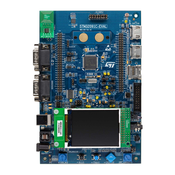
Figure 1. STM32091C-EVAL evaluation board picture
1. Picture not contractual.
February 2015
DocID026902 Rev 2
1/58
www.st.com
1
Advertisement
Table of Contents

Subscribe to Our Youtube Channel
Related Manuals for ST STM32091C-EVAL


Summary of Contents for ST STM32091C-EVAL
-
Page 1: Figure 1. Stm32091C-Eval Evaluation Board Picture
Smart card slot, RF E2PROM & Temperature sensor.) and develop your own applications. Extension headers make it possible to easily connect a daughter board or wrapping board for your specific application. An ST-LINK/V2-1 is integrated on the board as an embedded in-circuit debugger and programmer for the STM32 MCU. -
Page 2: Table Of Contents
Embedded ST-LINK/V2-1 ........10... - Page 3 Standard SWD connector CN11 ....... . 33 3.10 ST-LINK/V2-1 USB Type B connector CN12 ..... . 34 3.11 Audio jack CN13 .
- Page 4 List of tables UM1817 List of tables Table 1. Power source related jumpers ..........13 Table 2.
- Page 5 STM32091C-EVAL evaluation board picture ........
-
Page 6: Overview
Features • STM32F091VCT6 microncontroller with 256 KB Flash and 32 KB RAM • Three 5V power supply options: Power jack, ST-LINK/V2-1 USB connector or daughter board • Stereo audio jack which supports headset with microphone connected to DAC and ADC of STM32F091VCT6 •... -
Page 7: Delivery Recommendations
CN2 connector (top left corner of the board). For all information concerning the version of the MCU used on the board, its specification and possible related limitations, visit the ST web site to download relevant data sheet and errata sheet. -
Page 8: Hardware Layout And Configuration
Hardware Layout and configuration UM1817 Hardware Layout and configuration The STM32091C-EVAL evaluation board is designed around the STM32F091VCT6 (100- pin LQFP package). The hardware block diagram Figure 2 illustrates the connection between STM32F091VCT6 and peripherals (8x USARTs, RS232, RS485, Audio DAC,... -
Page 9: Figure 3. Stm32091C-Eval Board Layout
UM1817 Hardware Layout and configuration Figure 3. STM32091C-EVAL board layout TS1, TS2 Touch Buttons 8x USARTs connector CN6, CN7 Extension header HDMI Sink RF EEPROM daughter board connector HDMI Source STM32F091VCT6 MicroSD card RS232/RS485 CN10 SWD connector CN11 SWD connector... -
Page 10: Embedded St-Link/V2-1
ST-LINK/V2-1 (either available from Microsoft website or included in the USB driver for ST-LINK/V2 for XP). In case the STM32091C-EVAL evaluation board is connected to the PC before the driver is installed, some STM32091C-EVAL interfaces may be declared as “Unknown” in the PC device manager. -
Page 11: St-Link/V2-1 Firmware Upgrade
The ST-LINK/V2-1 embeds a firmware upgrade mechanism for in-situ upgrade through the USB port. As the firmware may evolve during the life time of the ST-LINK/V2-1 product (for example new functionality, bug fixes, support for new microcontroller families), it is recommended to visit www.st.com... -
Page 12: Figure 5. Structure Of Power Source
Hardware Layout and configuration UM1817 If this order is not respected, the board may be powered by VBUS first then E5V or D5V, and the following risks may be encountered: If more than 300mA current is needed by the board, the PC may be damaged or current can be limited by PC. -
Page 13: Table 1. Power Source Related Jumpers
Description JP15 is used to select one of the three possible power supply resources. For power supply jack (CN16) to the STM32091C-EVAL only, JP15 is set as shown to the right: For power supply from the daughter board connectors (CN7) to STM32091C-... -
Page 14: Mcu Power Modes Configuration
LD8 is lit when VDD<2V and in this case MCU is not functional. LD9 is lit when VDDA<2.4V and in this case analogue parts in STM32F091VCT6 are not functional. The LED LD5 is lit when the STM32091C-EVAL evaluation board is powered by the 5V correctly. -
Page 15: Clock Source
Risk of explosion if battery is replaced by an incorrect type. Dispose of used batteries according to the instructions. Clock Source Two clock sources are available on STM32091C-EVAL evaluation board for STM32F091VCT6 and RTC embedded. • X1, 32KHz Crystal for embedded RTC •... -
Page 16: Reset Source
PF1 is connected to extension connector CN7 when SB14 is closed. In such case R56 must be removed to avoid disturbance due to the 8Mhz quartz. Reset Source The reset signal of STM32091C-EVAL evaluation board is low active and the reset sources include: •... -
Page 17: Audio
The RS232 (with Hardware flow control CTS and RTS ), RS485 and IrDA communication is supported by D-type 9-pins RS232/RS485 connectors CN9, and IrDA transceiver U14 which is connected to USART1 of STM32F091VCT6 on STM32091C-EVAL evaluation board. The signal Bootloader_RESET (shared with CTS signal) and Bootloader_BOOT0 (shared with DSR signal) are added on RS232 connector CN9 for ISP support. -
Page 18: Touch Sensing Buttons
Default Setting: Not fitted Touch Sensing Buttons Two touch sensing buttons are supported on STM32091C-EVAL evaluation board and they are connected to 3 capacitive sensing channels (PD[12:14]) in group8 with active shield being connected to 2 capacitive sensing channels (PB11 and PB12) in group6. -
Page 19: Microsd Card
R37 must be removed to avoid disturbance due to the capacitor Note: Touch sensing buttons are fully functional only when STM32091C-EVAL is powered on in power mode 1 (both VDD and VDDA are connected to fixed 3.3V). It is potentially necessary to adjust the capacitor value of C8 and the firmware to adapt them to the voltage range from 1.65V to 3.6V of VDD on power mode 2 and 3. -
Page 20: Ldr (Light Dependent Resistor)
LDR (Light Dependent Resistor) The VDDA is divided by resistor bridge of LDR VT9ON1 and 8.2K resistor and connected to PA1 (COM1_IN+/ADC IN1) as shown below on STM32091C-EVAL evaluation board. Figure 6. GP comparator 1 It’s possible to compare LDR output with 1/4 band gap, 1/2 band gap, 3/4 band gap, band gap and DAC1 OUT and to connect LDR output to ADC IN1 for AD conversion. -
Page 21: Smart Card
2.14 Smart Card STMicroelectronics Smart card interface chip ST8024L is used on STM32091C-EVAL evaluation board for asynchronous 1.8V, 3V and 5V smart cards. It performs all supply protection and control functions based on the connections with STM32F091VCT6 listed in Table Table 13. -
Page 22: Rf E2Prom
DDC on HDMI_Source connector CN4. The I2C address of the RF EEPROM daughter board is 0b1010000. 2.17 HDMI CEC Two HDMI connectors CN3 and CN4 are available on STM32091C-EVAL board. • The connector CN3 is HDMI sink connector with –... -
Page 23: Ir Led And Ir Receiver
UM1817 Hardware Layout and configuration The CEC injector mode can be enabled by some PCB reworks for debugging purpose only: • Remove resistors R15, R17, R19, R28, R31, R35 and R38. • Close solder bridges SB2, SB3, SB4 and SB5. Note: The I/O PD11 must be set in open-drain output mode by firmware when working as an HPD signal control on the HDMI sink connector CN3. -
Page 24: Display And Input Devices
Hardware Layout and configuration UM1817 2.20 Display and Input devices The 2.4” color TFT LCD connected to SPI1 port of STM32F091VCT6 and 4 general purpose color LED’s (LD 1,2,3,4) are available as display device. The 4-direction joystick (B3) with selection key which connected to PA0 and supports wakeup feature. Tamper button (B2) are also available as input devices. -
Page 25: Connector
UM1817 Connector Connector 8x USARTs connector CN1 Figure 8. 8x USARTs connector CN1 Top View Table 16. 8x USARTs connector CN1 Pin number Description Pin number Description USART1_TX (PA9) USART2_RX (PD6) USART2_TX (PD5) USART3_RX (PD9) USART3_TX (PD8) USART4_RX (PC11) USART4_TX (PC10) USART5_RX (PB4) USART5_TX (PB3) USART6_RX (PF10) -
Page 26: Hdmi Sink Connector Cn3
Connector UM1817 Table 17. RF E2PROM connector CN2 Pin number Description Pin number Description I2C1_SDA (PB7) I2C1_SCL (PB6) EX_RESET(PD7) 2.3 HDMI Sink connector CN3 Figure 10. HDMI Sink connectors CN3 (front view) Table 18. HDMI Sink connectors CN3 Pin number Description Pin number Description... -
Page 27: Hdmi Source Connector Cn4
UM1817 Connector HDMI Source connector CN4 Figure 11. HDMI Source connectors CN4(front view) Table 19. HDMI Source connectors CN4 Pin number Description Pin number Description TMDS differential signal pair 1,3,4,6,7,9,10,12 I2C1_SDA (PB7) connected to CN3 CEC (PB10) 2,5,8,11,17 HDMI_5V_Source from power switch U3 I2C1_SCL (PB6) HPD (PD10) -
Page 28: Daughter Board Extension Connector Cn6 And Cn7
The space between these two connectors and position of power, GND and RESET pin are defined as a standard which allows developing common daughter boards for several ST evaluations boards. The standard width between CN6 pin1 and CN7 pin1 is 2700mils (68.58mm). - Page 29 UM1817 Connector Table 21. Daughter board extension connector CN6 (continued) How to disconnect with function block Description Alternative Function on STM32091C-EVAL board EX_RESET Remove R13 LED2 Remove R164 JOY_RIGHT Remove R189 8xUSART6_TX No Jumper mounted on CN1 PF10 8xUSART6_RX No Jumper mounted on CN1 SmartCard_1.8V...
-
Page 30: Table 22. Daughter Board Extension Connector Cn7
Connector UM1817 Table 22. Daughter board extension connector CN7 How to disconnect with function block Description Alternative Function on STM32091C-EVAL board PD14 TS_CT Remove C4, Close SB6 PD13 Remove R24, Close SB7 PD12 Remove R25, Close SB8 PC13 TAMPER_KEY Remove R181... -
Page 31: Microsd Connector Cn8
UM1817 Connector Table 22. Daughter board extension connector CN7 (continued) How to disconnect with function block Description Alternative Function on STM32091C-EVAL board PB10 HDMI_CEC Remove R12 PE14 SPI1_MISO Remove R45 PF11 BOOT0 Remove R46, open JP4 OSC_OUT Remove R56, Close SB14... -
Page 32: Table 23. Microsd Connector Cn8
Connector UM1817 Table 23. MicroSD connector CN8 Pin number Description MicroSDcard_CS (PE12) MicroSDcard_DIN(PE15) +3V3 MicroSDcard_CLK (PE13) Vss/GND MicroSDcard_DOUT(PE14) MicroSDcard_detect (PE11) Figure 14. RS232 and RS485 connector CN9 (front view) Table 24. RS232 and RS485 connector CN9 Pin number Description RS232_RX (PA10) RS232_TX (PA9) RS485_A Bootloader_BOOT0... -
Page 33: High Density Swd Connector Cn10
UM1817 Connector High density SWD connector CN10 Figure 15. High density SWD debugging connector CN10 (top view) Standard SWD connector CN11 Table 25. High density SWD debugging connector CN10 Pin number Description VDDIO2 SWDAT(PA13) SWCLK(PA14) RESET# DocID026902 Rev 2 33/58... -
Page 34: St-Link/V2-1 Usb Type B Connector Cn12
Pin number Description VDDIO2 SWDAT(PA13) SWCLK(PA14) 10K pull-down RESET# 10K pull-down 10K pull-down VDDIO2 3.10 ST-LINK/V2-1 USB Type B connector CN12 The USB connector CN12 is used to connect embedded ST-LINK/V2-1 to PC for debugging of board. 34/58 DocID026902 Rev 2... -
Page 35: Audio Jack Cn13
It is not populated by default and not for end user. 3.14 Power connector CN16 STM32091C-EVAL evaluation board can be powered from a DC 5V power supply via the external power supply jack (CN16) shown in Figure 15. The central pin of CN16 must be positive. -
Page 36: Analog Input Connector Cn18
Connector UM1817 Figure 18. Power supply connector CN16 3.15 Analog input connector CN18 Figure 19. Analog input-output connector CN18 Table 28. Analog input-output connector CN18 Pin number Description Analog input-output PC0 36/58 DocID026902 Rev 2... -
Page 37: Smart Card Connector Cn19
UM1817 Connector 3.16 Smart card connector CN19 Figure 20. Smart card connector CN19 Table 29. Smart card connector CN19 Pin number Description Detection pin of card presence Detection pin of card presence DocID026902 Rev 2 37/58... -
Page 38: Schematic
Schematic Figure 21. STM32091C-EVAL top view U_Audio U_MCU U_8x_USART Audio.SchDoc MCU.SchDoc 8x_USART.SchDoc Audio_OUT_L Audio_OUT_L 8xUSART1_TX 8xUSART1_TX Audio_OUT_R Audio_OUT_R 8xUSART2_TX 8xUSART2_TX Audio_IN Audio_IN 8xUSART3_TX 8xUSART3_TX 8xUSART4_TX 8xUSART4_TX U_CAN_SmartCard_IR 8xUSART5_TX 8xUSART5_TX CAN_SmartCard_IR.SchDoc 8xUSART6_TX 8xUSART6_TX CAN_RX CAN_RX 8xUSART7_TX 8xUSART7_TX CAN_TX CAN_TX 8xUSART8_TX 8xUSART8_TX... -
Page 39: Figure 22. Stm32091C-Eval Mcu
Figure 22. STM32091C-EVAL MCU Extension connector 20pF Left PD15 ETMB32.768B125B(hosonic) PC15 JOY_SEL PC15-OSC32_OUT PC14 PA10 LDR_OUT PC14-OSC32_IN SB11 PC13 20pF PC14 PA11 SmartCard_IO PC13 Tamper_key 11 12 PC12 PA12 PA13 SmartCard_RST PC12 USART5_TX SB12 13 14 PC11 PC15 Audio_OUT_L PC11... -
Page 40: Figure 23. Stm32091C-Eval Power
Figure 23. STM32091C-EVAL Power [N/A] ZEN056V130A24LS ST1L05BPUR +3V3_PG +3V3 CN16 +3V3 Power Supply 3.3V 220uF 20.5K[1%] Vout=1.22*(1+R1/R2) DC-10B SMAJ5.0A-TR 4.7uF 100nF BNX002-01 [N/A] 10uF[ESR<0.2ohm] 100nF 11.8K[1%] JP15 TP13 [N/A] Ground Ground U5V_ST_LINK ST1L05BPUR VDD_PG VDD_ADJ VDD_ADJ Header 3X2 +3V3_PG Power Supply VDD_ADJ [1.65V to 3.5V] considering potentiometer error tolerance 22.1K[1%]... -
Page 41: Figure 24. Stm32091C-Eval Audio
Figure 24. STM32091C-EVAL Audio VDD_ANA>2.2V VDD_ANA CN13 1.5nF R127 JP17 R180 Left 220uF R120 Default setting: close Right Microphone PJ-3028B Shutdown VOUT1 R121 R124 VDD_ANA Audio_OUT_L VIN1 VOUT2 VIN2 330nF Bypass 100nF [N/A] JP14 TS488IQT R143 R149 Audio_OUT_R 330nF R141 220uF 1.5nF... -
Page 42: Figure 25. Stm32091C-Eval Hdmi_Cec
Figure 25. STM32091C-EVAL HDMI_CEC FAULT HDMI_5V_Source Sink Source STMPS2141STR@54 4.7uF HDMI_5V_Sink TMDS_Data2+ TMDS_Data2- TMDS_Data1+ TMDS_Data1- TMDS_Data0+ TMDS_Data0- TMDS_Clock+ TMDS_Clock- 47151-0051 47151-0051 HDMI_5V_Sink PD10 HDMI_HPD_Source_5V 9012 PD11 HDMI_HPD_SINK FT pin & Open Drain mode needed 2N7002 PB13 I2C2_SCL_5V I2C1_SCL_5V PB14 I2C2_SDA_5V... -
Page 43: Figure 26. Stm32091C-Eval Lcd And Microsd Card
Figure 26. STM32091C-EVAL LCD and MicroSD card Input pin with pull-up PE11 SDcard_detect +3V3 100nF 100nF VCCA VCCB PE15 SPI1_MOSI_3V3 SPI1_MOSI PE14 SPI1_MISO_3V3 SN74LVC2T45DCUT SPI1_SCK_3V3 SPI1_MOSI_DIR SCLK +3V3 SPI1_MOSI_3V3 PE12 MicroSD_CS_3V3 Open drain pin! PJS008-2000 (SMS064FF or SMS128FF) +3V3 SPI MICRO SD... -
Page 44: Figure 27. Stm32091C-Eval Peripherals
Figure 27. STM32091C-EVAL Peripherals +3V3 Green R179 R165 LED1 +3V3 two pin header for external analog input VDD_ANA VDD<2V Orange CN18 R178 R164 R159 MCU not functional LED2 U21A R175 C100 1K[1%] R190 100nF Potentiometer R177 R191 0 R192 47... -
Page 45: Figure 28. Stm32091C-Eval Rs232, Rs485 And Irda
Figure 28. STM32091C-EVAL RS232, RS485 and IrDA +3V3 DB9-male USART2 100nF +3V3 SB15 R76 22K 100nF USART1_RTS_3V3 RS485_DIR R84 22K 100nF 100nF SB18 ST3485EBDR USART1_RTS_3V3 100nF T1IN T1OUT T2IN T2OUT T3IN T3OUT SB19 connector for USART2 & RS485 R1OUTB 100nF... -
Page 46: Figure 29. Stm32091C-Eval Temsensor And Rf Eeprom
Figure 29. STM32091C-EVAL TemSensor and RF EEPROM I2C1_SDA_5V I2C1_SCL_5V TempSensor_INT OS/INT STLM75M2F 100nF Temperature sensor Address:100100(A0) ACP_RST Open drain pin! SSM-104-L-DH RF E2P & Extension Connector RF E2P Address:1010(E2)00 Title: TemSensor & RF EEPROM Project: STM32091C-EVAL Size: Reference: MB1169 Revision:... -
Page 47: Figure 30. Stm32091C-Eval Can, Smartcard And Ir
Figure 30. STM32091C-EVAL CAN, SmartCard and IR VDD_IO2>3V +3V3 +3V3 Default setting: 1<->2 DB9-male CAN connector Default setting: Open 100nF +3V3 CAN_TX CANH CANL CAN_RX Vref IR_LED SFH409-2 SN65HVD230 SB20 R112 ESDCAN24-2BLY Optional [N/A] R116 R113 R114 +3V3 IR_OUT R103 R115 VDD>2.7V... -
Page 48: Figure 31. Stm32091C-Eval Swd
Figure 31. STM32091C-EVAL SWD VDD_IO2 [N/A] [N/A] PA13 SWDAT PA14 SWCLK RESET# ESDALC6V1W5 CN10 CN11 FTSH-105-01-L-DV VDD_IO2 VDD_IO2 [N/A] VDD_IO2 High Density SWD connector Standard SWD connector Title: Project: STM32091C-EVAL Size: Reference: MB1169 Revision: Date: 7/25/2014 Sheet:... -
Page 49: Figure 32. Stm32091C-Eval Touch Sensing
Figure 32. STM32091C-EVAL Touch Sensing PD14 DB_PD14 TS_CT 22nF(COG)GRM3195C1H223JA01L DB_PD13 DB_PD12 PD12 <----Active shield PD13 DB_PB12 PB12 SHIELD PB11 SHIELD_CT SB10 <----ESD resistor close to MCU pad DB_PB11 <----Touch Sensing diameter 10mm min on active shield diameter 12mm min TS_PAD... -
Page 50: Figure 33. Stm32091C-Eval St-Link/V2-1 (Swd Only)
Figure 33. STM32091C-EVAL ST-LINK/V2-1 (SWD only) R148 R146 BAT60JFILM JP18 +3V3_ST_LINK BAT60JFILM U16 LD3985M33R +3V3_ST_LINK R150 Vout 100K BAT60JFILM BYPASS 1uF_X5R_0603 +3V3_ST_LINK 1uF_X5R_0603 BAT60JFILM Board Ident: PC13=0 100nF 10nF_X7R_0603 100nF LD10 STM32F103CBT6 place it near USB connector mark: Over current... -
Page 51: Figure 34. Stm32091C-Eval 8X_Usart
Figure 34. STM32091C-EVAL 8x_USART 8xUSART1_TX 8xUSART2_RX 8xUSART2_TX 8xUSART3_RX PC11 8xUSART3_TX 8xUSART4_RX PC10 8xUSART4_TX 8xUSART5_RX PF10 8xUSART5_TX 8xUSART6_RX 8xUSART6_TX 11 12 8xUSART7_RX 8xUSART7_TX 13 14 8xUSART8_RX PA10 8xUSART8_TX 15 16 8xUSART1_RX Header 8X2 Title: 8x _USART Project: STM32091C-EVAL Size: Reference: MB1169... -
Page 52: Figure 35. Tft Lcd Daughter Board Mb895
Figure 35. TFT LCD daughter board MB895 Enable Enable DotClk DotClk BLGND HSYNC [N/A] HSYNC VSYNC VSYNC WR_SCL [N/A] WR/SCL #RESET [N/A] RESET [N/A] WR_SCL WR/SCL [N/A] BLGND PD10 PD10 BLGND PD17 PD11 PD17 BL_GND PD11 PD16 BL_Control PD12 PD16 BL_Control PD12 PD15... -
Page 53: Appendix A Appendix A Stm32091C-Eval Io Assignment
UM1817 Appendix A STM32091C-EVAL IO Assignment Appendix A Appendix A STM32091C-EVAL IO Assignment Table 30. IO assignement Pin No. Pin Name STM32091C-EVAL IO Assignment JOY_LEFT JOY_RIGHT TS_Shield_G7IO3 TS_Shield_CAP_G7IO4 LCD_CS VBAT VBAT PC13 TAMPER_KEY PC14-OSC32_IN OSC32_IN PC15-OSC32_OUT OSC32_OUT JOY_UP PF10 JOY_DOWN... - Page 54 Appendix A STM32091C-EVAL IO Assignment UM1817 Table 30. IO assignement (continued) Pin No. Pin Name STM32091C-EVAL IO Assignment PB1 or NPOR PB2 or NPOR SPI1_MOSI_DIR PE10 PE11 PE12 PE13 PE14 LCD/SD_SPI1_MISO PE15 LCD/SD_SPI1_MOSI PB10 USB_VBUS_detection PB11 VSS_2 VDD_2 PB12 PB13...
- Page 55 UM1817 Appendix A STM32091C-EVAL IO Assignment Table 30. IO assignement (continued) Pin No. Pin Name STM32091C-EVAL IO Assignment Smart_IO PA10 Smart_RST PA11 USB_DM PA12 USB_DP PA13 VSS_4 VDDIO2 VDDIO2 PA14 SWCLK / USART2_TX_BOOT PA15 USART2_RX_BOOT PC10 Smartcard_1.8V PC11 Smart_3/5V PC12...
-
Page 56: Appendix B Appendix B Mechanical Dimensions
Appendix B Mechanical Dimensions UM1817 Appendix B Appendix B Mechanical Dimensions Figure 36. Mechanical dimensions Table 31. Mechanical dimensions Symbol Size(mm) Symbol Size(mm) Symbol Size(mm) 68.58 77.44 26.67 2.54 111.76 2.54 5.715 24.12 5.715 17.70 19.08 114.3 23.81 172.72 56/58 DocID026902 Rev 2... -
Page 57: Revision History
UM1817 Revision History Revision History Table 32. Document Revision History Date Version Revision Details 31-Oct-2014 Initial Version Updated document title 06-Feb-2015 Updated schematics DocID026902 Rev 2 57/58... - Page 58 ST products and/or to this document at any time without notice. Purchasers should obtain the latest relevant information on ST products before placing orders. ST products are sold pursuant to ST’s terms and conditions of sale in place at the time of order acknowledgement.
Need help?
Do you have a question about the STM32091C-EVAL and is the answer not in the manual?
Questions and answers