
Related Manuals for WAGO TECHDOCS 750-600/000-001


Summary of Contents for WAGO TECHDOCS 750-600/000-001
- Page 1 Manual WAGO I/O System 750 750-600/000-001 End Module with Potential Group I/O Module for Terminating the Fieldbus Node; with Potential Group Version 1.0.1...
- Page 2 We wish to point out that the software and hardware terms as well as the trademarks of companies used and/or mentioned in the present manual are generally protected by trademark or patent. WAGO is a registered trademark of WAGO Verwaltungsgesellschaft mbH. Manual Version 1.0.1...
-
Page 3: Table Of Contents
WAGO I/O System 750 Table of Contents 750-600/000-001 End Module with Potential Group Table of Contents Notes about this Documentation ............. 4 Validity of this Documentation..............4 Copyright ....................4 Symbols ....................5 Number Notation ..................7 Font Conventions ................... 7 Important Notes .................. -
Page 4: Notes About This Documentation
Consider power layout of the WAGO I/O System 750! In addition to these operating instructions, you will also need the manual for the used fieldbus coupler or controller, which can be downloaded at www.wago.com. There, you can obtain important information including information on electrical isolation, system power and supply specifications. -
Page 5: Symbols
WAGO I/O System 750 Notes about this Documentation 750-600/000-001 End Module with Potential Group Symbols Personal Injury! Indicates a high-risk, imminently hazardous situation which, if not avoided, will result in death or serious injury. Personal Injury Caused by Electric Current! Indicates a high-risk, imminently hazardous situation which, if not avoided, will result in death or serious injury. - Page 6 Notes about this Documentation WAGO I/O System 750 750-600/000-001 End Module with Potential Group Additional Information: Refers to additional information which is not an integral part of this documentation (e.g., the Internet). Manual Version 1.0.1...
-
Page 7: Number Notation
WAGO I/O System 750 Notes about this Documentation 750-600/000-001 End Module with Potential Group Number Notation Table 1: Number Notation Number Code Example Note Decimal Normal notation Hexadecimal 0x64 C notation Binary '100' In quotation marks, nibble separated '0110.0100' with dots (.) -
Page 8: Important Notes
2.1.1 Subject to Changes WAGO GmbH & Co. KG reserves the right to provide for any alterations or modifications. WAGO GmbH & Co. KG owns all rights arising from the granting of patents or from the legal protection of utility patents. Third-party products are always mentioned without any reference to patent rights. -
Page 9: Technical Condition Of Specified Devices
These modules contain no parts that can be serviced or repaired by the user. The following actions will result in the exclusion of liability on the part of WAGO GmbH & Co. KG: •... -
Page 10: 2.1.4.1.2 Packaging
Important Notes WAGO I/O System 750 750-600/000-001 End Module with Potential Group Environmentally friendly disposal benefits health and protects the environment from harmful substances in electrical and electronic equipment. • Observe national and local regulations for the disposal of electrical and electronic equipment. -
Page 11: Safety Advice (Precautions)
WAGO I/O System 750 Important Notes 750-600/000-001 End Module with Potential Group Safety Advice (Precautions) For installing and operating purposes of the relevant device to your system the following safety precautions shall be observed: Do not work on devices while energized! All power sources to the device shall be switched off prior to performing any installation, repair or maintenance work. - Page 12 Important Notes WAGO I/O System 750 750-600/000-001 End Module with Potential Group Inadequate wire cross sections can cause temperature increases! To avoid increasing thermal risks, only use conductor cross-sections sufficient for the required maximum load current. The conductor cross-sections specified in the technical data refer exclusively to the mechanical connection capacity of the clamping points.
- Page 13 WAGO I/O System 750 Important Notes 750-600/000-001 End Module with Potential Group Protect the components against materials having seeping and insulating properties! The components are not resistant to materials having seeping and insulating properties such as: aerosols, silicones and triglycerides (found in some hand creams).
-
Page 14: Device Description
Device Description WAGO I/O System 750 750-600/000-001 End Module with Potential Group Device Description An end module must be snapped onto the assembly at the end of a fieldbus node. The end module completes the internal data bus, while providing correct data transmission. -
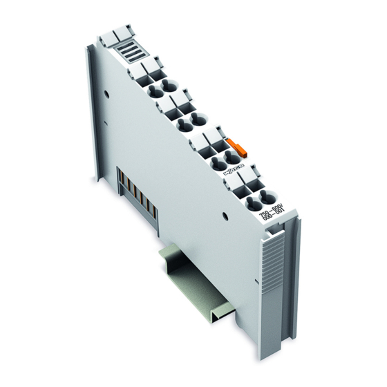
Page 15: View
WAGO I/O System 750 Device Description 750-600/000-001 End Module with Potential Group View Figure 1: View Table 3: Legend for Figure “View” Pos. Description Details See Section Marking possibility with Mini-WSB “Device Description” > … > CAGE CLAMP connectors ®... -
Page 16: Connectors
Device Description WAGO I/O System 750 750-600/000-001 End Module with Potential Group Connectors 3.2.1 Data Contacts/Local Bus Communication between the coupler/controller and the I/O modules as well as the system supply of the I/O modules is carried out via the local bus. It is comprised of 6 data contacts, which are available as self-cleaning gold spring contacts. -
Page 17: Cage Clamp ® Connectors
WAGO I/O System 750 Device Description 750-600/000-001 End Module with Potential Group 3.2.3 CAGE CLAMP ® Connectors Figure 3: CAGE CLAMP ® Connector Table 4: Legend for Figure “CAGE CLAMP ® Connector“ Designation Connector Function 0 … 230 V …... -
Page 18: Schematic Diagram
Device Description WAGO I/O System 750 750-600/000-001 End Module with Potential Group Schematic Diagram Figure 4: Schematic Diagram Manual Version 1.0.1... -
Page 19: Technical Data
WAGO I/O System 750 Device Description 750-600/000-001 End Module with Potential Group Technical Data 3.6.1 Device Table 5: Technical Data – Device Width 12 mm Height 69.8 mm Depth 100 mm Weight 48 g 3.6.2 Rated Voltages Table 6: Technical Data – Rated Voltages Supply voltage (system) 5 VDC;... -
Page 20: Climatic Environmental Conditions
Device Description WAGO I/O System 750 750-600/000-001 End Module with Potential Group 3.6.4 Climatic Environmental Conditions Table 9: Technical Data – Climatic Environmental Conditions Surrounding air temperature, operation 0 °C … 55 °C Surrounding air temperature, storage −25 °C … +85 °C Operating altitude 0 …... -
Page 21: Approvals
WAGO I/O System 750 Device Description 750-600/000-001 End Module with Potential Group Approvals For current approvals, please go to: www.wago.com/<Item number>. The following approvals have been granted to 750-600/000-001 I/O modules: Conformity Marking UL E175199 for use in Ordinary Location... -
Page 22: Standards And Guidelines
Device Description WAGO I/O System 750 750-600/000-001 End Module with Potential Group Standards and Guidelines 750-600/000-001 I/O modules meet the following requirements on emission and immunity of interference: EMC CE-Emission of interference EN 61000-6-3 EMC CE-Immunity to interference EN 61000-6-2... -
Page 23: Mounting
Do not install the device on or in the vicinity of easily flammable materials! Mounting Sequence Fieldbus couplers, controllers and I/O modules of the WAGO I/O System 750 are snapped directly on a carrier rail in accordance with the European standard EN 60175 (DIN 35). -
Page 24: Inserting And Removing Devices
Mounting WAGO I/O System 750 750-600/000-001 End Module with Potential Group Starting with the fieldbus coupler or controller, the I/O modules are mounted adjacent to each other according to the project design. Errors in the design of the node in terms of the potential groups (connection via the power contacts) are recognized, as the I/O modules with power contacts (blade contacts) cannot be linked to I/O modules with fewer power contacts. -
Page 25: Removing The End Module
WAGO I/O System 750 Mounting 750-600/000-001 End Module with Potential Group 4.2.2 Removing the End Module Remove the end module from the assembly by pulling the release tab. Figure 6: Removing the End Module The electrical connections for the data contacts are disconnected when removing the end module. -
Page 26: Connect Devices
Do not connect more than one conductor at one single connection! If more than one conductor must be routed to one connection, these must be connected in an up-circuit wiring assembly, for example using WAGO feed- through terminals. For opening the CAGE CLAMP ®... -
Page 27: Connection Examples
WAGO I/O System 750 Connect Devices 750-600/000-001 End Module with Potential Group Connection Examples The following connection examples are possible in connection with the I/O module 750-677/0x0-000: Figure 8: Connection to I/O Module 750-677 (all Channels with Inverted Configured Output). -
Page 28: List Of Figures
List of Figures WAGO I/O System 750 750-600/000-001 End Module with Potential Group List of Figures Figure 1: View ....................15 Figure 2: Data Contacts ..................16 Figure 3: CAGE CLAMP ® Connector ..............17 Figure 4: Schematic Diagram ................18 Figure 5: Snap the End Module into Place ............24 Figure 6: Removing the End Module ..............25... -
Page 29: List Of Tables
WAGO I/O System 750 List of Tables 750-600/000-001 End Module with Potential Group List of Tables Table 1: Number Notation ................... 7 Table 2: Font Conventions .................. 7 Table 3: Legend for Figure “View” ..............15 Table 4: Legend for Figure “CAGE CLAMP ®... - Page 30 WAGO GmbH & Co. KG Postfach 2880 • D - 32385 Minden Hansastraße 27 • D - 32423 Minden Phone: +49 571 887 – 0 Fax: +49 571 887 – 844169 E-Mail: info@wago.com Internet: www.wago.com...
Need help?
Do you have a question about the TECHDOCS 750-600/000-001 and is the answer not in the manual?
Questions and answers