Table of Contents
Advertisement
Advertisement
Table of Contents

Related Manuals for Sanyo MCO-18AC UV


Summary of Contents for Sanyo MCO-18AC UV
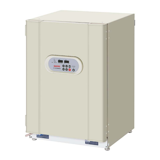
- Page 1 INSTRUCTION MANUAL MCO-18AC(UV) MCO-18AC Incubator...
- Page 2 7FB6P101567000 (29 June 2010) 5-5, Keihan-Hondori 2-Chome Moriguchi City, Osaka 570-8677 Japan Printed in Japan...
-
Page 3: Table Of Contents
CONTENTS INTRODUCTION P. 2 PRECAUTIONS FOR SAFE OPERATION P. 3 LABELS ON THE INCUBATORS P. 6 ENVIRONMENTAL CONDITIONS P. 7 INCUBATOR COMPONENTS P. 8 Control panel and keypad P. 10 Remote alarm terminal P. 11 INSTALLATION SITE P. 12 INSTALLATION P. -
Page 4: Introduction
■ Contact Sanyo sales representative or agent if any page of the manual is lost or page order is incorrect. ■ Contact Sanyo sales representative or agent if any point in this manual is unclear or if there are any inaccuracies. -
Page 5: Precautions For Safe Operation
PRECAUTIONS FOR SAFE OPERATION It is imperative that the user complies with this manual as it contains important safety advice. Items and procedures are described so that you can use this unit correctly and safely. If the precautions advised are followed, this will prevent possible injury to the user and any other person. - Page 6 WARNING Do not use the unit outdoors. Current leakage or electric shock may result if the unit is exposed to rain water. Only qualified engineers or service personnel should install the unit. The installation by unqualified personnel may cause electric shock or fire. Install the unit on a sturdy floor and take an adequate precaution to prevent the unit from turning over.
- Page 7 WARNING Ensure you do not inhale or consume medication or aerosols from around the unit at the time of maintenance. These may be harmful to your health. Never splash water directly onto the unit as this may cause electric shock or short circuit. Never put containers with liquid on the unit as this may cause electric shock or short circuit when the liquid is spilled.
-
Page 8: Labels On The Incubators
CAUTION Use a dedicated power source (a dedicated circuit with a breaker) as indicated on the rating label attached to the unit. A branched circuit may cause fire resulting from abnormal heating. Connect the power supply plug to the power source firmly after removing the dust on the plug. A dusty plug or improper insertion may cause a heat or ignition. -
Page 9: Environmental Conditions
ENVIRONMENTAL CONDITIONS This equipment is designed to be safe at least under the following conditions (based on the IEC 61010-1): ■ Indoor use; ■ Altitude up to 2000 m; ■ Ambient temperature 5 C to 40 ■ Maximum relative humidity 80% for temperature up to 31 C decreasing linearly to 50% relative humidity at 40 ■... -
Page 10: Incubator Components
INCUBATOR COMPONENTS 9 (inside) Handles 19,20 (inside) For MCO-18AC(UV) or when an optional UV system kit MCO-18UVS3 is installed. Handles 10, 11 For MCO-18AC(UV) or when an optional UV system kit MCO-18UVS3 is installed. Rear Right Side Rear Left Side... - Page 11 18. Humidifying pan cover*: Prevents UV light being exposed to the chamber. When filling the pan, lift the front side and take out the pan. See page 30 for details. 19. UV lamp*: Sanyo UV lamp does not generate ozone. Never look at the UV light directly. For replacement, contact Sanyo sales representative or agent.
-
Page 12: Control Panel And Keypad
See page 31 and 32 for the details. Also, used to change the UV lamp ON period. See page 21 for the details. Note: This operation affects the basic performance. When calibrating the CO density, contact a Sanyo sales representative or agent. -
Page 13: Remote Alarm Terminal
12. Alarm buzzer stop key (BUZZER): Press this key to silence the buzzer when the alarm operates and the buzzer sounds (The remote alarm is not stopped). 13. CO gas supply line indicator (A/B): The lamp for the supply line currently in use lights up provided that MCO-21GC automatic CO cylinder changeover system (option) is installed. -
Page 14: Installation Site
INSTALLATION SITE To operate this incubator properly and to obtain maximum performance, install the incubator in a location with the following conditions: WARNING Ventilate a room air occasionally when using CO gas for control. The gas density will increase in an enclosed small room and high level of gas density can be hazardous to health. -
Page 15: Installation
INSTALLATION 1. Remove the packaging materials and tapes Remove all transportation packaging materials and tapes. Open the doors and ventilate the incubator. If the outside panels are dirty, clean them with a neutral detergent and wipe it up with a wet cloth. WARNING Do not put the packing plastic bag within reach of children as suffocation may result. -
Page 16: Connection Of Co 2 Gas Cylinder
Connection of CO gas cylinder WARNING Check the gas type and ensure that it is fit for the purpose. Make sure that all pipes are connected correctly and are not liable to become disconnected. Ensure that the gas pressure is set at the specified value. -
Page 17: Preventing Contamination
PREVENTING CONTAMINATION To prevent contamination of the chamber, select an appropriate location for installation as well as the complete disinfection of the chamber components. ● Avoid hot and humid location Avoid location with high temperature and/or humidity as the presence of bacteria in the air is greater than in normal environment. -
Page 18: Precautions For Cultures
PRECAUTIONS FOR CULTURES ● Do not subject to direct air flow Do not allow the air for air conditioning to hit the incubator or door directly. Direct hit may cause condensation or contamination. ● Allow adequate space between the cultures When storing cultures in the chamber, keep the Petri dishes or bottles containing the cultures sufficiently apart from each other to allow adequate air circulation. -
Page 19: Start-Up Of Incubator
START-UP OF INCUBATOR When start the test operation or the operation, follow these steps as below. 1. Install the incubator referring to “INSTALLATION” on page 13. 2. Remove all transportation packaging materials and tapes on the attachments in the chamber. Then clean and sterilize the chamber and inner attachments. -
Page 20: Setting The Chamber Temperature And Co
SETTING THE CHAMBER TEMPERATURE AND CO DENSITY Table below shows the basic procedure for setting the chamber temperature and CO density. The upper limit alarm temperature setting is also shown in the table. Perform key operations in the sequence indicated in the table. The example in the table is based on the assumption that the desired temperature is 37 C and CO density is 5%. -
Page 21: Uv Lamp(Mco-18Ac(Uv) Or Mco-18Ac With Mco-18Uvs3)
ON time reaches approximately 1,000 hours, the UV indicator blinks (when the UV lamp is not lit). It is recommended that the UV lamp be quickly replaced at this point. Contact a Sanyo sales representative or agent for information on replacing the UV lamp. -
Page 22: Precautions When Using The Uv Lamp
Precautions when using the UV lamp The clauses below are applicable when the model is MCO-18AC(UV) or an optional UV system kit MCO-18UVS3 is installed. WARNING Do not look directly at UV light. UV light is harmful to the eyes. ... -
Page 23: Setting The Uv Lamp On Period
It will also shorten the service life of the UV lamp. When replacing the UV lamp, contact a Sanyo sales representative or agent. Pressing calibration key (CAL) for about 5 seconds leads the calibration mode. In the calibration mode, the calibration of temperature and CO density is possible. -
Page 24: Lighting The Uv Lamp For 24 Hours
Lighting the UV lamp for 24 hours The clauses below are applicable when the model is MCO-18AC(UV) or an optional UV system kit MCO-18UVS3 is installed. If the chamber has been contaminated by dirt or by spilling the medium, use the following procedure to decontaminate the chamber by lighting the UV lamp for 24 hours. -
Page 25: Key Lock Function
KEY LOCK FUNCTION This incubator is provided with a key lock function. When the key lock is ON, change of temperature or density setting through the key pad is not available. Note: The key lock is set in OFF mode (L0) at the factory. Display Mode Function... -
Page 26: Water Level Sensor(Mco-18Ac(Uv) Or Mco-18Ac With Mco-18Uvs3)
WATER LEVEL SENSOR (MCO-18AC(UV) or MCO-18AC with MCO-18UVS3) Water level sensor for the humidifying pan is used with the MCO-18AC(UV) or the MCO-18AC with an optional UV system kit MCO-18UVS3 installed. The sensor is set in active position with respect to the installation of the humidifying pan. -
Page 27: Alarms, Safety, And Self-Diagnosis
(BUZZER). When MCO-21GC is installed, press the alarm buzzer stop key (BUZZER) to silence the alarm after changeover of gas supply line. • If one of E05 to E18 (except for E12, E13, and E14) is displayed, contact a Sanyo sales representative or agent. -
Page 28: Setting Of Alarm Resume Time
SETTING OF ALARM RESUME TIME The alarm buzzer is silenced by pressing alarm buzzer stop key (BUZZER) on the control panel during alarm condition (The remote alarm is not stopped). The buzzer will be activated again after certain suspension if the alarm condition is continued (The remote alarm continues). -
Page 29: Routine Maintenance
ROUTINE MAINTENANCE Cleaning the chamber and inner attachments When the chamber of the incubator is contaminated, the chamber and internal attachments should be cleaned and sterilized as follows. WARNING Before performing any repairs or maintenance, turn OFF the power switch and unplug the incubator. Failure to do say may result in electric shock or injury. - Page 30 6. Pull out the humidifying pan. (See Fig. 4.) 7. Loosen the two screws securing the fan cover and take off the fan cover. (See Fig. 5.) 8. Lift the duct and remove it from the pins on the rear side. (See Fig. 6.) Duct Fan cover Humidifying pan...
- Page 31 15. (MCO-18AC(UV) or when an optional UV system kit MCO-18UVS3 is installed) Wipe the water level sensor with sterilizing alcohol. Be careful not to leave any residual alcohol. When cleaning the sensor, take care not to apply excessive force to the lead wires. 16.
-
Page 32: Filling The Humidifying Pan
Filling the humidifying pan Use the following procedure to fill the humidifying pan or to replace the water. 1. (MCO-18AC(UV) or when an optional UV system kit MCO-18UVS3 is installed)Lift the humidifying pan cover. After that pull the humidifying pan forward. (See Fig. -
Page 33: Calibration Temperature Calibration
CALIBRATION Temperature calibration 1. Press the calibration key (CAL) for approximately 5 seconds again to enter the temperature calibration input mode. 2. The left digit of the digital temperature indicator blinks, and the digital CO density indicator goes out. 3. Set the present correct temperature with the digit shift key ( ) and numerical value shift key ( then press the enter key (ENT). -
Page 34: Co 2 Calibration
CALIBRATION calibration Span setting Span setting should be done under stable condition of temperature, humidity, and CO density. 1. Press the calibration key (CAL) once to enter the CO calibration pre-conditioning mode. 2. Confirm blinking the decimal point in the digital CO density indicator. -
Page 35: Troubleshooting
CO gas density normal, it may be that dust on the HEPA filter prevents the gas flow. Contact a Sanyo sales representative or agent. • The CO control method for the incubator is the ON-OFF method. CO... -
Page 36: Disposing Of The Co 2 Incubator
Note: If the problem still has not been solved after trying the above checks and countermeasures, or for any problems not covered here, contact a Sanyo sales representative or agent. DISPOSING OF THE CO INCUBATOR When disposing of the CO incubator, contact a Sanyo sales representative or agent. - Page 37 Waste Electrical and Electronic Equipment (WEEE) Directive-2002/96/EC (English) Your SANYO product is designed and manufactured with high quality materials and components which can be recycled and reused. This symbol means that electrical and electronic equipment, at their end-of-life, should be disposed of separately from your household waste.
- Page 38 (French) Votre produit Sanyo est conçu et fabriqué avec des matèriels et des composants de qualité supérieure qui peuvent être recyclés et réutilisés. Ce symbole signifie que les équipements électriques et électroniques en fin de vie doivent être éliminés séparément des ordures ménagères.
- Page 39 Por favor, ajude-nos a conservar o ambiente em que vivemos! (Italian) Il vostro prodotto SANYO è stato costruito da materiali e componenti di alta qualità, che sono riutilizzabili o riciclabili. Prodotti elettrici ed elettronici portando questo simbolo alla fine dell’uso devono essere smaltiti separatamente dai rifiuti casalinghi.
- Page 40 Alstublieft help allen mee om het milieu te beschermen. (Swedish) Din SANYO produkt är designad och tillverkad av material och komponenter med hög kvalitet som kan återvinnas och återanvändas. Denna symbol betyder att elektriska och elektroniska produkter, efter slutanvändande, skall sorteras och lämnas separat från Ditt hushållsavfall.
-
Page 41: Automatic Co 2 Cylinder Changeover
AUTOMATIC CO CYLINDER CHANGEOVER An automatic CO cylinder changeover system (MCO-21GC) is available as an optional accessory. This system switches the gas supply line when one CO gas cylinder is empty. Note: The installation of the MCO-21GC must be performed only by qualified service personnel. Install the MCO-21GC and then perform the following procedure 1. -
Page 42: Stacking Incubators
STACKING INCUBATORS Use the following procedure to stack incubators. This work is potentially dangerous, so contact a Sanyo sales representative or agent. CAUTION Select a floor that is strong enough to support the stacked incubators. Never stack three or more incubators. Doing so is dangerous. - Page 43 Front panel Stacking plate B Front side Stacking plate A Protective sticker Hook Fig.A...
-
Page 44: Specifications
Extra tray (MCO-47ST) including 2 tray supports, Half tray (MCO-25ST) Automatic CO cylinder changeover system (MCO-21GC), Roller base (MCO-18RB) RS232C/RS485 Interface (MTR-480), Ethernet (LAN) Interface (MTR-L03) SANYO Data acquisition software (MTR-5000) Note: Design or specifications will be subject to change without notice. -
Page 45: Performance
PERFORMANCE Ambient temperature +5 C to 50 C (ambient temperature; 5 C to 35 Temperature control range ± 0.25 C (ambient temperature; 25 C, setting; 37 C, CO 5%, no load) Temperature distribution ± 0.1 C (ambient temperature; 25 C, setting; 37 C, CO 5%, no load) Temperature variation... -
Page 46: Safety Check Sheet
CAUTION Please fill in this form before servicing. Hand over this form to the service engineer to keep for his and your safety. Safety check sheet 1. Incubator contents : □Yes □Yes □No □No Risk of infection: □Yes □Yes □No □No Risk of toxicity: □Yes...
Need help?
Do you have a question about the MCO-18AC UV and is the answer not in the manual?
Questions and answers