Table of Contents
Advertisement
Quick Links
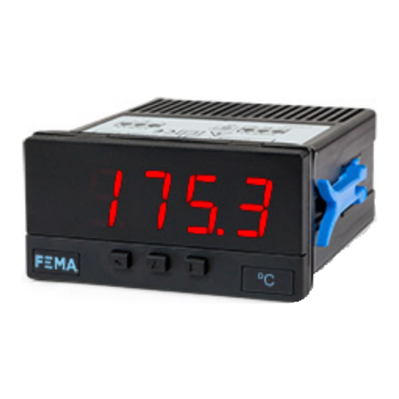
Series S . S40-T
Panel meter for temperature signals
PANEL METERS
Panel meter for process temperature, in compact size 72 x 36 mm, and standard 14 mm digit height.
Accepts signals from Pt100 / RTD (2 and 3 wires) and thermocouples J, K, T, E, S, R, N, C, L and X. Read-
ing configurable in ºC or ºF. Manual offset configurable. Configurable cold junction compensation.
Sensor break detection. Reading with 4 digit display. Fast access to alarm setpoints, 'on power up'
function, configurable reading brightness. Universal AC and DC power. Up to 2 optional modules for
output and control (relays, transistor, control SSR, analog outputs, Modbus RTU communications, RS-
485 ASCII, RS-232, ...)
2264r08
ELECTRONICS
FOR
PANEL METERS . SIGNAL CONVERTERS . LARGE DISPLAYS
Tel. (+34) 93.729.6004 info@fema.es
User's Manual
INDUSTRIAL
AUTOMATION
www.fema.es
Advertisement
Table of Contents

Related Manuals for Fema S Series


Summary of Contents for Fema S Series
- Page 1 Sensor break detection. Reading with 4 digit display. Fast access to alarm setpoints, ‘on power up’ function, configurable reading brightness. Universal AC and DC power. Up to 2 optional modules for output and control (relays, transistor, control SSR, analog outputs, Modbus RTU communications, RS- 485 ASCII, RS-232, ...) www.fema.es Tel. (+34) 93.729.6004 info@fema.es 2264r08...
-
Page 2: Table Of Contents
FEMA ELECTRÓNICA . Series S . S40-T 1. Panel meter S40-T Panel meter in compact 72 mm size for temperature signals Panel meter in compact 72 x 36 mm size, for temperature signals, with Independent alarms configurable as maximum or minimum, with 1 14 mm digit height. -
Page 3: Front View
FEMA ELECTRÓNICA . Series S . S40-T 1.2 Front view 1.5 Signal connections - Pt100 / RTD Alarms For Pt100 / RTD with 2 wires 1 2 3 Pt100 2 wires Logo Units For Pt100 / RTD with 3 wires 1 2 3 Button ‘UP’ Button ‘SQ’... -
Page 4: Technical Specifications
FEMA ELECTRÓNICA . Series S . S40-T 1.8 Technical specifications Thermocouples J, K, T, E, S, R, N, C, L and X Digits (thermocouple X is 10 uV/ºC linear signal) number of digits resolution 1º 7 segments led (see Table 1) -
Page 5: Messages And Errors
FEMA ELECTRÓNICA . Series S . S40-T 1.8 Technical specifications (cont.) 1.9 Messages and errors Mechanical The error messages are shown on display in flash mode. mounting panel connections plug-in screw terminal housing material ABS, polycarbonate (V0) Messages and errors weight <150 grams... -
Page 6: How To Operate The Menus
FEMA ELECTRÓNICA . Series S . S40-T 1.10 How to operate the menus The instrument has two menus accessible to the user : Example of operation inside the ‘configuration menu’. ‘Configuration menu’ (key SQ) (<) 1. The SQ (<) key enters into the ‘Fast access’... -
Page 7: Configuration Menu
FEMA ELECTRÓNICA . Series S . S40-T 1.11 Configuration menu 1.11.1 Initial set-up Press ‘SQ’ (<) for 1 second to access the ‘configuration menu’. For a description on how to operate inside the menus see section 1.10 . For a full vision of the ‘configuration menu’ structure see To configure the initial set up of the instrument, select the type of 1.12... -
Page 8: Alarms
FEMA ELECTRÓNICA . Series S . S40-T 1.11 Configuration menu (cont.) 1.11.3 Alarms The ‘Alarms’ (‘ALr’) menu configures the independent activation of Alarms up to 2 relay outputs (or transistor or control SSR), installed with the R1 (or T1 or SSR) optional modules (see section 2.1). For outputs up to 4 relays, see special modules R2 and R4 at section 2.8. -
Page 9: Display Filters
FEMA ELECTRÓNICA . Series S . S40-T 1.11 Configuration menu (cont.) 1.11.4 Display filters The instrument provides several functions associated to the reading Display Steps of the display values • the ‘Steps’ (‘StEP’) function allows to define minimum reading steps, which will be done in steps of 1, 2, 5, 10, 20 or 50 counts. -
Page 10: Menu 'On Power Up
FEMA ELECTRÓNICA . Series S . S40-T 1.11 Configuration menu (cont.) 1.11.7 Menu ‘On Power Up’ The ‘On Power Up’ (‘on.Pu’) menu configures functions to apply at On Power-Up Delay Seconds start-up. It applies only to instrument restart after power loss. It does not apply to instrument restart due to change in configuration. -
Page 11: Firmware Version
FEMA ELECTRÓNICA . Series S . S40-T 1.11 Configuration menu (cont.) 1.11.11 Firmware version The ‘Version’ (‘VEr’) menu informs of the current firmware version Version installed in the module. Minimum 1.11.12 Brightness Brightness At the ‘Brightness’ (‘LIGh’) menu select the light intensity for the Standard front leds. -
Page 12: Full Configuration Menu
FEMA ELECTRÓNICA . Series S . S40-T 1.12 Full configuration menu Press ‘SQ’ (<) for 1 second to access the ‘Configuration 1.11 menu’. See section for a description of each menu entry. Alarms Pt100 / RTD 2 wires Input Pt100 / RTD 3 wires Alarm 1... - Page 13 FEMA ELECTRÓNICA . Series S . S40-T 1.11 Full configuration menu (cont.) Minimum Key UP Tools Setpoint 1 Brightness (fast access) Standard Setpoint 2 Maximum Memory of maximum Memory of Configuration menu for the module installed at Opt.1 minimum Option 1 Configuration menu for the module installed at Opt.2 Option 2...
-
Page 14: To Access The Instrument
FEMA ELECTRÓNICA . Series S . S40-T 1.13 To access the instrument You may need to access the inside of the instrument to add or re- place internal modules. Use a flat screwdriver to unlock the upper clips marked with ‘A’. Then unlock the lower clips marked with ‘B’ and remove the front cover. -
Page 15: Precautions On Installation
FEMA ELECTRÓNICA . Series S . S40-T 1.15 Precautions on installation strument must be assured. Do not expose the instrument to excess of humidity. Maintain Risk of electrical shock. Instrument terminals can be connected clean by using a humid rag and do NOT use abrasive products such as alcohols, solvents, to dangerous voltage. -
Page 16: Output And Control Modules
FEMA ELECTRÓNICA . Series S . S40-T 2. Output and control modules 2.1 Module R1 2.2 Module T1 The R1 module provides 1 relay output to to install at digital panel The T1 module provides 1 transistor output to install at digital panel meters from Series S, up to a maximum of 2 relays in a single meter. -
Page 17: Module Ssr
FEMA ELECTRÓNICA . Series S . S40-T 2.3 Module SSR 2.4 Module AO The SSR module provides 1 output to control SSR relays, to install at The AO module provides 1 analog output with 4/20 mA or 0/10 Vdc digital panel meters from Series S, up to a maximum of 2 SSR con- configurable output range. -
Page 18: Module Rtu
FEMA ELECTRÓNICA . Series S . S40-T 2.5 Module RTU 2.6 Module S4 The S4 module provides a RS-485 communications module for Series The RTU module provides a Modbus RTU communications module for Series S of panel meters. The RTU module implements function S of panel meters. -
Page 19: Module S2
FEMA ELECTRÓNICA . Series S . S40-T 2.7 Module S2 2.8 Modules R2, R4 The S2 module provides a RS-232 communications module for Series The R2 and R4 modules provide 2 and 4 relay outputs for Series S S of panel meters. ASCII protocol with ‘Master’ / ‘Slave’ architecture.
Need help?
Do you have a question about the S Series and is the answer not in the manual?
Questions and answers