Table of Contents
Advertisement
Quick Links
Datasheet
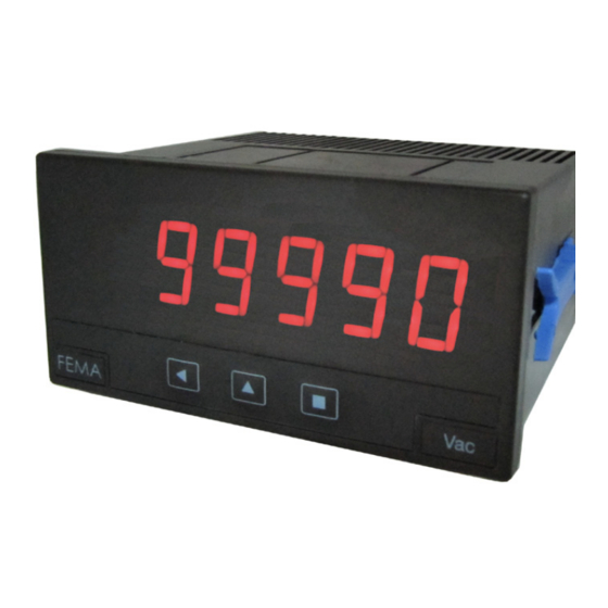
Series M40
Panel Meters
Model M40-P
Panel meter for process signals in mA and Vdc. Accepts both active and passive
signals, monopolar and bipolar, from 2 and 3 wire transducers.
standard. Display in 4 or 5 digits.
linearization,
signal autocorrection, "measure" function, peak&hold, alarms with double setpoints, 5
levels of brightness, ... Universal AC and DC power modules and up to 3 modules for
signal retransmission and control.
USER'S MANUAL
(2145R00)
Amplicon.com
Sales:
+44 (0) 1273 570 220
maximum and minimum display memory, scalable reading, filters, steps,
IT and Instrumentation for industry
Website:
www.amplicon.com
Panel meter 96x48mm
for process signals
( ±20mA and ±10Vdc)
Provides excitation voltage for transducers. Segment
Email:
sales@amplicon.com
Housing 96x48mm DIN
Advertisement
Table of Contents

Related Manuals for Fema M40 Series


Summary of Contents for Fema M40 Series
- Page 1 Datasheet Series M40 Panel Meters Panel meter 96x48mm for process signals Model M40-P ( ±20mA and ±10Vdc) Panel meter for process signals in mA and Vdc. Accepts both active and passive signals, monopolar and bipolar, from 2 and 3 wire transducers. Housing 96x48mm DIN standard.
-
Page 2: Order Reference
Datasheet Meter M40-P Panel meter 96x48mm size for process signals Panel meter for process signals in mA and Vdc, active and “measure” function (visualizes input signal without scaling), passive, monopolar and bipolar, from 2 or 3 wire transducers. offset and signal high autocorrection (assigns the actual Provides +15V (max. -
Page 3: Signal Connections
Datasheet er’s Manual M40-P Front View Signal Connections Alarms Active current loop 4/20mA / ±20mA 1 2 3 Jumper 5 closed Current Signal generator Common Passive current loop 4/20mA / ±20mA Logo Button LE Button SQ Units Button UP 1 2 3 Jumper 5 closed Rear View 2 Wire... -
Page 4: Technical Data
Datasheet Technical Data Technical Data (cont.) Digits 4 (or 5 with last digit fixed to zero) Thermal stability Type 7 segments, red offset 25 ppm/ºC Height 14 mm span* 60 ppm/ºC Display maximum 9999 (99990) *span drift includes the offset drift Display minimum -9999 (-99990) Decimal point... -
Page 5: Information Menu
Datasheet er’s Manual M40-P Information Menu Operating the Information Menu To enter the “Information Menu” press the SQ button. The “Information Menu” allows to visualize information and does mA or Vdc not allow to modify the configuration of the instrument. It is Configuration not affected by the “PASSWord”... -
Page 6: Configuration Menu
Datasheet Configuration Menu Range 4/20mA See menu for Alarm1 Input Range 0/10Vdc See menu for Alarm1 Range ±20mA See menu for Alarm1 Range ±10Vdc Display Scaling Input Low Fixed Digits Fix digits Display Low Input High Average Display High Press LE to change selection Decimal Point Steps Auto correction... -
Page 7: Default Factory Configuration
Datasheet er’s Manual M40-P Configuration Menu Peak & Hold Time (Sec.) Tools Advanced Points Input0 Display0 display (Segment linearization) Input10 Display10 Enter signal values (“Input”) and associated display val- ues (“Display“) for each linearization point. Then activate “Act” to “On”. In case of error verify the points data. Activate Reset Password... - Page 8 Datasheet Hysteresis (hySt) - Value from “0” to “9999”. Points of hyster- Input Menu esis. The hysteresis applies on the deactivation of the alarm. The input menu allows for selection of the input signal range. Delay (dEL) - Value from “0.0” to “99.9” seconds. Delay to be Options are 4/20mA, 0/10Vdc, ±20mA and ±10Vdc.
-
Page 9: Tools Menu
Datasheet er’s Manual M40-P Peak & Hold (P.hLd) - Peak & Hold function detects sharp the alarm type (“Max/Min”), the setpoint, the hysteresis value, drops in the displayed value, and holds the display if a display the activation delay and the value of setpoint2 (“Off” or the drop is detected. -
Page 10: Accessing The Instrument
The scope of this warranty is limited to the repair cost of the instrument, not being the manufacturer eligible for responsibility on additional damages or costs. . CE Declaration of Conformity Manufacturer FEMA ELECTRÓNICA, S.A. Immunity rules Altimira 14 - Pol. Ind. Santiga 61000-6-2 Generic rules of immunity E08210 - Barberà...
Need help?
Do you have a question about the M40 Series and is the answer not in the manual?
Questions and answers