
Related Manuals for Fema TAS-1-IDC


Summary of Contents for Fema TAS-1-IDC
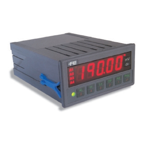
- Page 1 TAS-1 Series INTELLIGENT PANEL METERS Intelligent Panel Meters TAS-1-IAC AC Current TAS-1-IDC DC Current TAS-1-VAC AC Voltages TAS-1-VDC DC Voltages USER’S MANUAL info@fema.es www.fema.es FEMA ELECTRÓNICA - Page 1...
-
Page 2: Table Of Contents
7.3.5- Modbus frame structure-I 7.3.6- Character Structure 7.3.7- Modbus frame structure-II 7.4- Peak, Valley, Hold, Tare, Reset - TEK Option Board 7.4.1- Available Functions 7.4.2- Connections 7.4.3- Configuration 8.- CE Certificate / Warranty 9.- Safety Information FEMA ELECTRÓNICA - Page 2... -
Page 3: If This Is The First Time You Work With A Tas-1 Meter
Connector for PC Green Led - keypad acting as direct access Configuration (PCConnector cable needed) Note .- The 2 relay outputs and the Optional Boards are OPTIONAL and are NOT INCLUDED with the basic unit. FEMA ELECTRÓNICA - Page 3... -
Page 4: Programming Menu
↵ ↵ ↵ ↵ ↵ Decimal Point Position Keypad Blocking menu, remember the 5 digit INPUT number you are about to enter. The instrument will not accept any future order until the same 5 digit password is reintroduced. FEMA ELECTRÓNICA - Page 4... -
Page 5: Adjusting The Low Indication
3-Validate the changes pressing 3-Press message «INPUT» shows the configuration has been accepted 4-Message «Cr Hi» shows the unit has corrected the high level value, linking the current input signal to the high indication value memorized (HI keypad) FEMA ELECTRÓNICA - Page 5... -
Page 6: Alarm Configuration
Led is active when alarm is inactive Securty Mode deactivated Alarm text active **Output relay are inactive until the set point is Alarm text inactive reached for the first time. Text associated with alarm led FEMA ELECTRÓNICA - Page 6... -
Page 7: Manual Adjustment
0/5 AAC Lo - Low Level Indication Lo - Low Level Indication HI - High Level Indication 650.0 HI - High Level Indication 5.000 Decimal Point 0 0 0.0 0 Decimal Point 0 0.0 0 0 FEMA ELECTRÓNICA - Page 7... -
Page 8: Messages And Errors
Additional options are shown in the small own «SAVE TO FILE» / «LOAD FROM FILE» buttons. window to the right. COM Selection «START COM» Button Options Configuration Window Signal/Display adjustments Input Signal Ranges «WRITE_D» Button Forces writing configuration to the instrument FEMA ELECTRÓNICA - Page 8... -
Page 9: Technical Specifications
1 2 3 4 5 6 7 8 9 0 1 2 3 4 5 6 7 8 9 1 2 3 4 5 6 7 8 9 0 1 2 3 4 5 6 7 8 9 15mm 96mm FEMA ELECTRÓNICA - Page 9... -
Page 10: Available Options .- Installing And Configuring
3.- To configure the analog output you need to know the analog output signal and the related display indication Input Signal Indication Analog Output 4 mA 0 Vdc (00000 miliVots) 20 mA 100.00 10 Vdc (10000 miliVolts) FEMA ELECTRÓNICA - Page 10... -
Page 11: Configuration
Note2 : The TEK board can share the expansion bus with the TSAT option of with the R485M option, or can be directly connected to the bus alone. Nota3 : Boards TSAT for Analog Output and R485M for Modbus output can not be integrated simultaneously on the same instrument. FEMA ELECTRÓNICA - Page 11... -
Page 12: Modbus Output - R485M Option Board
Note2 : The length of all registers is 2 bytes, defined as LSB and MSB. b1=1 AL2 in ON state b3=1 AL4 in ON state MSB (Most Significant Byte) is the first to be transmitted LSB (Least Significant Byte) us the second to be transmitted FEMA ELECTRÓNICA - Page 12... -
Page 13: Connections And Bus Terminator
RESPONSE : Communication SLAVE to MASTER ADDRESS 1 CARACTER Instrument Address FUNCTION 1 CARACTER Function 04H, register read LENGTH 1 CARACTER Number of data characters following DATA X CARACTERES Response data* 2 CARACTERES Control Checksum FEMA ELECTRÓNICA - Page 13... -
Page 14: Available Functions
↵ ↵ ↵ ↵ ↵ When entering code «14 22» to apply a unit reset, the TEK option is configured as follows : INPUT o ERROR STATE FUNCTION CONTROL 1 HOLD CONTROL 2 HOLD CONTROL12 FEMA ELECTRÓNICA - Page 14... - Page 15 TAS-1-IAC or repaired by personnel or companies without the official authorization DIRECTIVES of FEMA ELECTRÓNICA, S.A. This Warranty is VOID also for damages EUROPEAN DIRECTIVE FOR LOW VOLTAGE D73/23/CEE AMENDED BY D93/68/CEE. caused by defective or inappropriate applications. Equipments powered from 50 to 1000 Vac. and /or from 75 to 1500 Vdc.
- Page 16 Pol. Ind. Santiga • Altimira, 14 (T14 - N2) • P.O. Box 49 • Tel. (+34) 93 729 6004 • E-08210 BARBERÀ DEL VALLÈS (Barcelona) España info@fema.es • www.fema.es • Fax (+34) 93 729 6003 • FEMA ELECTRÓNICA - Page 16...
Need help?
Do you have a question about the TAS-1-IDC and is the answer not in the manual?
Questions and answers