
Related Manuals for Fema BAR MBR Series


Summary of Contents for Fema BAR MBR Series
- Page 1 USER’S MANUAL SERIES BAR · Model MBR CONFIGURABLE BAR GRAPH METER SERIES SPECIAL www.fema.es 4/20 m A 0/10 V dc ±20 m A ±10 V dc SPECIAL Process Process Process Process Potentiometer 5245r01...
-
Page 2: Table Of Contents
21. Warranty ......19 16.1 Option customized 22. CE declaration of conformity ....19 FEMA · MANUFACTURING FOR INDUSTRIAL AUTOMATION... -
Page 3: How To Order
• configure alarms 1 and 2 (see section 11.2). • connect alarms 1 and 2 (see section 15.1). 6. If analog output is installed: User’s Manual www.fema.es/docs/5245_MBR_manual_en.pdf • configure analog output (see section 11.13). Datasheet www.fema.es/docs/5247_MBR_datasheet_en.pdf • connect analog output (see section 15.2). -
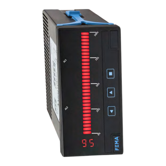
Page 4: Front View
0 Vdc n.c. + Vdc 60 to 240 Vac neutral n.c. phase Table 5 EXTERNAL CONTROL CONNECTIONS Input terminals EXTERNAL CONTROL shortcircuit between terminal 1 (external external control control) and terminal 4 (common) to activate external control FEMA · MANUFACTURING FOR INDUSTRIAL AUTOMATION... -
Page 5: Technical Specifications
SERIES BAR · Model MBR SERIES SPECIAL . BAR METERS 8. Technical specifications 9. Dimensions (mm (inch)) INPUT SIGNAL RANGES process unipolar 4/20 mA, 0/10 Vdc 48 mm process bipolar ±20 mA, ±10 Vdc (1.89 in.) type of signal active or passive, passive, the instrument 75 mm 96 mm provides +15 Vdc excitation voltage to power (0.63 in.) -
Page 6: How To Operate The Instrument
When ‘Eco’ function is active and the display is powered off, the decimal point remains active (flashing) indicating that the display is off due to the ‘Eco’ function. To configure the ‘Eco’ function, see section 11.12. FEMA · MANUFACTURING FOR INDUSTRIAL AUTOMATION... -
Page 7: How To Operate The 'Fast Access' Menu
SERIES BAR · Model MBR SERIES SPECIAL . BAR METERS 10. How to operate the instrument (cont.) 10.4 How to operate the ‘fast access’ menu 10.5 How to activate the ‘fast functions’ HOW TO ENTER THE ‘FAST ACCESS’ MENU HOW TO ACTIVATE ‘FAST FUNCTIONS’ With the instrument in ‘normal mode’... -
Page 8: Configuration Menu
(default). Select Flash excess segments ‘Flash excess segments’ (EX) to flash bar graph segments on the alarm section (including hysteresis affected segments). Select ‘No No flash flash’ (no) to deactivate bar graph flashing. FEMA · MANUFACTURING FOR INDUSTRIAL AUTOMATION... -
Page 9: Average Filter
SERIES BAR · Model MBR SERIES SPECIAL . BAR METERS 11. Configuration menu (cont.) 11.3 Average filter At the ‘Average filter’ (13) menu entry, configure the strength of the filter Filter strength (0 to 99) applied to the display. The filter can be used to reduce oscillations on Average filter noisy signals. -
Page 10: Password
The input low signal is fixed to 0 mA and 0 Vdc and can not be modified. Correction applied to the input high level (20 mA, 10 Vdc) applies also to the symmetric negative input signal (-20 mA, -10 Vdc). FEMA · MANUFACTURING FOR INDUSTRIAL AUTOMATION... -
Page 11: Firmware Version
SERIES BAR · Model MBR SERIES SPECIAL . BAR METERS 11. Configuration menu (cont.) 11.10 Firmware version The ‘Version’ (2.3) menu entry is located inside the ‘Tools’ (20) menu. Version The ‘Version’ (2.3) menu entry informs about the firmware version running in the instrument. -
Page 12: Full Configuration Menu
F. correction high Hysteresis 0 to 99 Alarm 2 hysteresis Version Flash on alarm Alarm 2 flash Flash excess segments No flash Factory reset Filter strength (0 to 99) ‘Eco’ mode Seconds Average filter FEMA · MANUFACTURING FOR INDUSTRIAL AUTOMATION... -
Page 13: Error Codes
SERIES BAR · Model MBR SERIES SPECIAL . BAR METERS 12. Full configuration menu (cont.) 13. Factory default parameters (10) Input signal 4/20 mA = 0/100 % (0.1) (11) Alarm 1 Alarm 1 setpoint (1.S) 100 % Analog output Bar low Alarm 1 type (1.t) maximum (MX) Alarm 1 hysteresis (1.h) 1 % Alarm 1 flash (1.F) yes (YS) -
Page 14: Output And Control Modules
Table 9 CONNECTIONS FOR A1 AND A2 RELAY MODULES Table 10 CONNECTIONS FOR M1 MODULE Opt.2 (A2) Opt.1 (A1) Opt.1 (M1) com. com. Vexc. 4/20 mA common G H I A B C A B C FEMA · MANUFACTURING FOR INDUSTRIAL AUTOMATION... - Page 15 SERIES BAR · Model MBR SERIES SPECIAL . BAR METERS 15. Output and control modules (cont.) CONNECTIONS Image 3 ANALOG OUTPUT CONFIGURATION PARAMETERS For an active 4/20 mA loop, connect terminal A (+15 Vdc excitation voltage, current output) and terminal B (mA signal, current input). For a passive 4/20 mA loop, connect terminal B (mA signal, current output) and terminal C (common, current input).
-
Page 16: Other Options
16. Other options 16.1 Option customized Instruments can be adapted to your needs. This includes: • improved technical specifications • custom functions • factory pre-configurations • others as requested Image 4 Custom instruments FEMA · MANUFACTURING FOR INDUSTRIAL AUTOMATION... -
Page 17: Accessories
SERIES BAR · Model MBR SERIES SPECIAL . BAR METERS 17. Accessories 17.1 Adapter DRA 17.4 WME wall mount housing The DRA is an adapter that allows to install a standard 96 x 48 mm (1/8 The WME is allows to install a standard 96 x 48 mm (1/8 DIN) size panel DIN) size panel meters into a standard 35 mm OMEGA DIN rail. - Page 18 Optional modules can be replaced, changed, added or removed simply by placing the proper module at the proper location. See section 15 for a list of available optional modules. Table 12 Internal structure of the instrument ‘Optional module Opt.1’ ‘Front filter’ ‘Optional module Opt.2’ ‘Display’ ‘Motherboard’ ‘Housing’ FEMA · MANUFACTURING FOR INDUSTRIAL AUTOMATION...
-
Page 19: Precautions On Installation
Within the warranty period and after examination by the manufacturer, the unit will be repaired or substituted when found to be defective. Extended warranty available at https://www.fema.es/warranty w w w. fem a . es...
Need help?
Do you have a question about the BAR MBR Series and is the answer not in the manual?
Questions and answers