Table of Contents
Advertisement
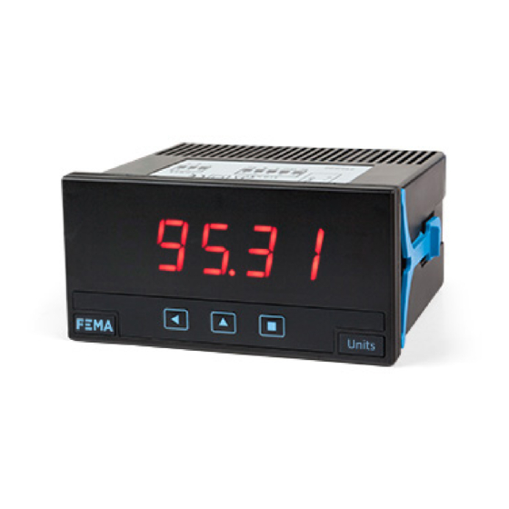
Series C . C40-D
Multisignal panel meter
PANEL METERS. OEM APPLICATIONS
Multisignal digital panel meter, configurable to work as AC and DC voltmeter (up to 600 Vac / dc), AC and DC
ammeter (up to 5 Aac / dc), accepts process signals (mA, Vdc), thermocouples, resistive temperature probes
(Pt, Ni, PTC and NTC), resistances, potentiometers and frequency. Configurable. Standard 96 x 48 mm size
(1/8 DIN). Scalable reading with 4 digits (9999 / -1999). 'Fast access' function to alarm setpoints, 'external
control' to activate predefined functions, 'Eco' mode for low consumption, selectable dual scaling, 5 levels
of configurable brightness. Single universal power supply 18 to 265 Vac/dc. Optional modules for output
and control (relays, analog output, Modbus RTU). Recommended for OEM applications.
4149r07
ELECTRONICS
FOR
PANEL METERS . SIGNAL CONVERTERS . LARGE DISPLAYS
Tel. (+34) 93.729.6004 info@fema.es
User's Manual
INDUSTRIAL
AUTOMATION
OEM
APPLICATIONS
YOUR METER !
www.fema.es
Advertisement
Table of Contents


Need help?
Do you have a question about the C Series and is the answer not in the manual?
Questions and answers