Table of Contents
Advertisement
Quick Links
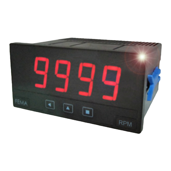
Series K . K40-C1
Impulse counter, ratemeter
PANEL mEtErS
Impulse counter, ratemeter and periodmeter, with 20 mm digit height. Accepts all type of impulse
sensors (NPN, PNP, Namur, TTL, inductive, mechanical, encoders, ...). Provides configurable excitation
voltage to power-up the transducer. Standard 96 x 48 mm size (1/8 DIN). Reading with 4 digit display.
Fast access to alarm setpoints, special modes for fast counting and for slow ratemeter applications,
'on power up' function, configurable reading brightness. Universal AC and DC power. Up to 3 optional
modules for output and control (relays, analog outputs, Modbus RTU communications, RS-485 ASCII,
RS-232, ...)
3590r00
ELECTRONICS
FOR
PANEL METERS . SIGNAL CONVERTERS . LARGE DISPLAYS
Tel. (+34) 93.729.6004 info@fema.es
User's Manual
INDUSTRIAL
AUTOMATION
www.fema.es
Advertisement
Table of Contents

Related Manuals for Fema K Series


Summary of Contents for Fema K Series
- Page 1 Fast access to alarm setpoints, special modes for fast counting and for slow ratemeter applications, ‘on power up’ function, configurable reading brightness. Universal AC and DC power. Up to 3 optional modules for output and control (relays, analog outputs, Modbus RTU communications, RS-485 ASCII, RS-232, ...) www.fema.es Tel. (+34) 93.729.6004 info@fema.es 3590r00...
-
Page 2: Table Of Contents
FEMA ELECTRÓNICA . Series K . K40-C1 1. Panel meter K40-C1 Counter, ratemeter and periodmeter, 96 x 48 mm (1/8 DIN), with 20 mm digit height Panel meter 96 x 48 mm (1/8 DIN) and 4 digits with 20 mm digit Front protection IP54 with optional IP65. -
Page 3: How To Order
FEMA ELECTRÓNICA . Series K . K40-C1 1.1 How to order model Power Option 1 Option 2 Option 3 Others -NBt (85-265 Vac/dc) (1 relay) (no buttons) (11/60 Vdc, (analog output) (front IP65) 24 Vac, 48 Vac) -RTU (Modbus RTU) -
Page 4: Front View
FEMA ELECTRÓNICA . Series K . K40-C1 1.6 Front view 1.9 Rear view Option 3 Option 1 Option 2 Alarms Logo Units 1 2 3 4 5 8 9 0 Signal Power Button ‘LE’ Button ‘UP’ Button ‘SQ’ (see section 3.2) (see section 1.7) -
Page 5: Technical Specifications
FEMA ELECTRÓNICA . Series K . K40-C1 1.11 Technical specifications Digits number of digits Counter Mode Frequency Section 7 segments led ‘FAST’ mode max. 250 KHz 1.16 color Counter digit height 20 mm normal mode max. 9 KHz 1.19.2 Reading Counter + inhibition max. -
Page 6: Function 'Trigger Sense
FEMA ELECTRÓNICA . Series K . K40-C1 1.13 Function ‘Trigger Sense’ The trigger level is automatically configured when selecting a sensor from the ‘Sensor / Configuration’ (‘SnSr’ / ‘Auto’) menu list. the trig- ger level can be also manually modified from the ‘SnSr’ / ‘TrIG’ menu entry. -
Page 7: How To Operate The Menus
FEMA ELECTRÓNICA . Series K . K40-C1 1.17 How to operate the menus The instrument has two menus accessible to the user : Example of operation inside the ‘configuration menu’. ‘Configuration menu’ (key SQ) (<) 1. The SQ (<) key enters into the ‘Fast access’... -
Page 8: Configuration Menu
FEMA ELECTRÓNICA . Series K . K40-C1 1.19 Configuration menu 1.19.1 Initial set-up Press ‘SQ’ (<) for 1 second to access the ‘configuration menu’. For a description on how to operate inside the menus see section 1.17 . For a full vision of the ‘configuration menu’ structure see To configure the initial set up of the instrument, select the function 1.20... -
Page 9: Configuration For 'Cnq.2
FEMA ELECTRÓNICA . Series K . K40-C1 1.19 Configuration menu (cont.) 1.19.3 Configuration for ‘cnq.2’ Multiplier Configuration menu for mode ‘counter quadrature’ (‘cnq.2’). to- 1 to 9999 Multiplier tal impulses received are multiplied by the value of the ‘multiplier’ Conf. counter quadrature (‘MuLt’) register and divided by the ‘divider’... -
Page 10: Configuration For 'Cnd.5
FEMA ELECTRÓNICA . Series K . K40-C1 1.19 Configuration menu (cont.) 1.19.6 Configuration for ‘cnd.5’ Multiplier Configuration menu for mode ‘counter differential’ (‘cnd.5’). to- 1 to 9999 Configuration Multiplier tal impulses received are multiplied by the value of the ‘multiplier’... -
Page 11: Configuration For 'Prd.8
FEMA ELECTRÓNICA . Series K . K40-C1 1.19 Configuration menu (cont.) • select the ‘edges’ to count for each quadrature cycle (‘q.124’). Se- 1 imp. per cycle lect ‘1--1’ for 1 impulse per quadrature cycle. Select ‘1--2’ for 2 im- pulses per quadrature cycle. - Page 12 FEMA ELECTRÓNICA . Series K . K40-C1 1.19 Configuration menu (cont.) • ‘Pulls on channel A’ (‘PuL.A’) - activates pull resistors at chan- No pull resistor nel A. Select ‘P.uP’ to activate pull-up resistors (needed for NPN Pulls on channel A sensors).
-
Page 13: Alarms
FEMA ELECTRÓNICA . Series K . K40-C1 1.19 Configuration menu (cont.) 1.19.11 Alarms Alarms The ‘Alarms’ (‘ALr’) menu configures the independent activation of up to 3 relay outputs, installed with the R1 optional modules (see section 2.1). For outputs up to 4 and 6 relays, see special modules r2,... -
Page 14: Fast Access
FEMA ELECTRÓNICA . Series K . K40-C1 1.19 Configuration menu (cont.) 1.19.12 Fast access The ‘UP’ (5) key at the front of the instrument gives access to a list Tools of functions configurable by the operator. See section 1.17 for an ex- planation on how to operate the ‘fast access’... -
Page 15: Menu 'Key Le
FEMA ELECTRÓNICA . Series K . K40-C1 1.19 Configuration menu (cont.) 1.19.15 Menu ‘Key LE’ No function The ‘LE’ (3) key at the front of the instrument can be configured to Key LE activate several functions. Only one function can be assigned to the ‘LE’... -
Page 16: Full Configuration Menu
FEMA ELECTRÓNICA . Series K . K40-C1 1.20 Full configuration menu Press ‘SQ’ (<) for 1 second to access the ‘Configuration menu’. See 1.19 section for a description of each menu entry. Multiplier Counter 1 to 9999 Multiplier Conf. counter... - Page 17 FEMA ELECTRÓNICA . Series K . K40-C1 1.20 Full configuration menu (cont.) Max. waiting time ‘SLOW’ mode Average filter Filter strength 1 to 1000 Sec. Average filter Filter strength Mechanical contact Sensor Automatic conf. Namur Multiplier NPN 2 wire 1 to 9999 Conf.
- Page 18 FEMA ELECTRÓNICA . Series K . K40-C1 1.20 Full configuration menu (cont.) by rising edge Activation for Tools reset by falling edge Key UP Setpoint 1 (‘fast access’) Excitation voltage Setpoint 2 Setpoint 3 Memory of maximum Antirrebound filter (0 to 1000 mSec.)
-
Page 19: Factory Configuration
FEMA ELECTRÓNICA . Series K . K40-C1 1.20 Full configuration menu (cont.) 1.21 Factory configuration Function counter (‘cn.1’) With left zeros Decimal point Counter configuration Left zeros Without left zeros Multiplier Divider Preset mode Password ‘FAST’ Sensor Pulls on channel A... -
Page 20: To Access The Instrument
Operation must be performed by qualified personnel only. 1.23 Modular system K Series panel meters are designed to create a modular system. this modular system allows for addition, replacement or substitution of any of the internal modules conforming the instrument. Below is a graphic explanation for the position of each module. -
Page 21: Precautions On Installation
FEMA ELECTRÓNICA . Series K . K40-C1 1.24 Precautions on installation soon as power is connected. The instrument does not have protection fuse, Risk of electrical shock. Instrument terminals can be connected the fuse must be added during installation. to dangerous voltage. -
Page 22: Output And Control Modules
2.1 Module R1 2.2 Module AO The R1 module provides 1 relay output to K Series panel meters. Up The AO module provides 1 analog output with 4/20 mA or 0/10 Vdc to a maximum of 3 R1 modules can be installed in a single instru- configurable output range. -
Page 23: Module Rtu
(20 mm digit height) and BDF Series (60 mm and 100 mm digit installed (see section 1.23). height). The RTU module can be ordered pre-installed into a K Series panel • Access to display values, alarm status, memory of maximum and meter, or standalone for delayed installation, as it does not require minimum, alarm setpoints, ... -
Page 24: Module S2
(see section 1.23). The R2, R4 and R6 modules can be ordered pre-installed into a K The S2 module can be ordered pre-installed into a K Series panel Series panel meter, or standalone for delayed installation, as they do meter, or standalone for delayed installation, as it does not require not require soldering or special configuration. - Page 25 FEMA ELECTRÓNICA . Series K . K40-C1...
-
Page 26: Other Options
FEMA ELECTRÓNICA . Series K . K40-C1 3. Other options 3.1 Option NBT Instruments without front key- pad. To configure the instrument, remove the meter from the panel and remove the front filter. Inter- nal press buttons for configuration are accessible. Optionally, request... -
Page 27: Accessories
4.3 Adapter DRA-M Benchtop housing for M Series Adapter for DIN rail mount, for and K Series panel meters. Handle m Series and K Series panel me- with three selectable positions. ters. Power connector with manual switch and fuse holder. - Page 28 Compact 72 x 36 mm ‘Customized’ Isolators Low cost instruments MODBUS truermS truermS rS-485 Load FEMA ELECTRÓNICA, S.A. Altimira 14 - Pol. Ind. Santiga E08210 Barberà del Vallès rS-232 BARCELONA - SPAIN Pt100 Tel. +34 93.729.6004 Fax +34 93.729.6003 Custom Shunts Pt100 info@fema.es...
Need help?
Do you have a question about the K Series and is the answer not in the manual?
Questions and answers