Table of Contents
Advertisement
Quick Links
Series S . S40-C1
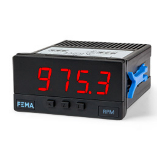
Impulse counter, ratemeter
PANEL METERS
Impulse counter, ratemeter and periodmeter, in compact size 72 x 36 mm, and standard 14 mm digit
height. Accepts all type of impulse sensors (NPN, PNP, Namur, TTL, inductive, mechanical, encoders,
...). Provides configurable excitation voltage to power-up the transducer. Reading with 4 digit display.
Fast access to alarm setpoints, special modes for fast counting and for slow ratemeter applications,
'on power up' function, configurable reading brightness. Universal AC and DC power. Up to 2 optional
modules for output and control (relays, transistor, control SSR, analog outputs, Modbus RTU commu-
nications, RS-485 ASCII, RS-232, ...)
2983r11
ELECTRONICS
FOR
PANEL METERS . SIGNAL CONVERTERS . LARGE DISPLAYS
Tel. (+34) 93.729.6004 info@fema.es
User's Manual
INDUSTRIAL
AUTOMATION
www.fema.es
Advertisement
Table of Contents

Subscribe to Our Youtube Channel
Related Manuals for Fema S40-C1


Summary of Contents for Fema S40-C1
- Page 1 ELECTRONICS INDUSTRIAL AUTOMATION PANEL METERS . SIGNAL CONVERTERS . LARGE DISPLAYS Series S . S40-C1 Impulse counter, ratemeter PANEL METERS Impulse counter, ratemeter and periodmeter, in compact size 72 x 36 mm, and standard 14 mm digit height. Accepts all type of impulse sensors (NPN, PNP, Namur, TTL, inductive, mechanical, encoders, ...).
-
Page 2: Table Of Contents
Index 1. Panel meter S40-C1 ..... . 2 1.19.14 Menu ‘Key LE’ ....14 1.1 How to order . -
Page 3: How To Order
FEMA ELECTRÓNICA . Series S . S40-C1 1.1 How to order Model Power Option 1 Option 2 Others (85-265 Vac/dc) (1 relay) (green led) (11/60 Vdc, (analog output) 24 Vac, 48 Vac) -RTU (Modbus RTU) (RS-485) (RS-232) (1 transistor) -SSR (1 control SSR) (empty) 1.2 Impulse counter modes 1.5 Functions included... -
Page 4: Front View
FEMA ELECTRÓNICA . Series S . S40-C1 1.6 Front view 1.9 Rear view Option 1 Option 2 Alarms Logo Units 1 2 3 4 5 8 9 0 Signal Power Button ‘UP’ Button ‘SQ’ Button ‘LE’ (see section 1.10) (see section 1.7) Front reset ‘Fast access‘... -
Page 5: Technical Specifications
FEMA ELECTRÓNICA . Series S . S40-C1 1.11 Technical specifications Digits number of digits Counter Mode Frequency Section 7 segments led ‘FAST’ mode active max. 250 KHz 1.19.2 color red or green Counter digit height 14 mm normal mode max. 9 KHz 1.19.2... -
Page 6: Function 'Trigger Sense
FEMA ELECTRÓNICA . Series S . S40-C1 1.13 Function ‘Trigger Sense’ The trigger level is automatically configured when selecting a sensor from the ‘Sensor / Configuration’ (‘SnSr’ / ‘Auto’) menu list. The trig- ger level can be also manually modified from the ‘SnSr’ / ‘TrIG’ menu entry. -
Page 7: How To Operate The Menus
FEMA ELECTRÓNICA . Series S . S40-C1 1.17 How to operate the menus The instrument has two menus accessible to the user : Example of operation inside the ‘configuration menu’. ‘Configuration menu’ (key SQ) (<) 1. The SQ (<) key enters into the ‘Fast access’... -
Page 8: Configuration Menu
FEMA ELECTRÓNICA . Series S . S40-C1 1.19 Configuration menu Press ‘SQ’ (<) for 1 second to access the ‘configuration menu’. 1.19.1 Initial set-up For a description on how to operate inside the menus see section 1.17 . For a full vision of the ‘configuration menu’ structure see To configure the initial set up of the instrument, select the function 1.20... -
Page 9: Configuration For 'Cnq.2
FEMA ELECTRÓNICA . Series S . S40-C1 1.19 Configuration menu (cont.) 1.19.3 Configuration for ‘cnq.2’ Multiplier Configuration menu for mode ‘counter quadrature’ (‘cnq.2’). To- 1 to 9999 Multiplier tal impulses received are multiplied by the value of the ‘multiplier’ Conf. counter quadrature (‘MuLt’) register and divided by the ‘divider’... -
Page 10: Configuration For 'Cnd.5
FEMA ELECTRÓNICA . Series S . S40-C1 1.19 Configuration menu (cont.) 1.19.6 Configuration for ‘cnd.5’ Multiplier Configuration menu for mode ‘counter differential’ (‘cnd.5’). To- 1 to 9999 Configuration Multiplier tal impulses received are multiplied by the value of the ‘multiplier’... -
Page 11: Configuration For 'Prd.8
FEMA ELECTRÓNICA . Series S . S40-C1 1.19 Configuration menu (cont.) • for slow frequencies activate the ‘SLoW’ parameter configuring the ‘tIME’ parameter between 1 and 1000 seconds. Configure the ‘nuMb’ Max. waiting time parameter between 1 and 32 impulses. See section 1.15 for more in- ‘SLOW’... - Page 12 FEMA ELECTRÓNICA . Series S . S40-C1 1.19 Configuration menu (cont.) • ‘Pulls on channel A’ (‘PuL.A’) - activates pull resistors at chan- No pull resistor nel A. Select ‘P.uP’ to activate pull-up resistors (needed for NPN Pulls on channel A sensors).
-
Page 13: Alarms
FEMA ELECTRÓNICA . Series S . S40-C1 1.19 Configuration menu (cont.) 1.19.11 Alarms Alarms The ‘Alarms’ (‘ALr’) menu configures the independent activation of up to 2 relay outputs (or transistor or control SSR), installed with the R1 (or T1 or SSR) optional modules (see section 2.1). For outputs up Alarm 1... -
Page 14: Fast Access
FEMA ELECTRÓNICA . Series S . S40-C1 1.19 Configuration menu (cont.) 1.19.12 Fast access The ‘UP’ (5) key at the front of the instrument gives access to a list of func- Tools tions configurable by the operator. See section 1.17 for an explanation on how to operate the ‘fast access’... -
Page 15: Menus 'Overrange / Underrange
FEMA ELECTRÓNICA . Series S . S40-C1 1.19 Configuration menu (cont.) 1.19.16 Menus ‘Overrange / underrange’ Flash The ‘Counter overrange’ (‘c.orG’) and ‘Counter underrange’ (‘c.urG’) Counter To zero overrange parameters configure the behavior of the instrument when reading is higher than ‘9999’ (overrange) or lower than ‘-1999’ (underrange). -
Page 16: Full Configuration Menu
FEMA ELECTRÓNICA . Series S . S40-C1 1.20 Full configuration menu Press ‘SQ’ (<) for 1 second to access the ‘Configuration menu’. See 1.19 section for a description of each menu entry. Multiplier Counter 1 to 9999 Multiplier Conf. counter... - Page 17 FEMA ELECTRÓNICA . Series S . S40-C1 1.20 Full configuration menu (cont.) Max. waiting time Max. waiting time ‘SLOW’ mode ‘SLOW’ mode Number of pulses Number of pulses Filter strength Filter strength Average filter Average filter (0 = disabled) (0 = disabled)
- Page 18 FEMA ELECTRÓNICA . Series S . S40-C1 1.20 Full configuration menu (cont.) rising edge Channel A acti- Tools falling edge vation by rising edge Key UP Setpoint 1 Activation for (‘fast access’) reset by falling edge Setpoint 2 Excitation voltage Memory of...
-
Page 19: Factory Configuration
FEMA ELECTRÓNICA . Series S . S40-C1 1.20 Full configuration menu (cont.) 1.21 Factory configuration Function counter (‘cn.1’) With left zeros Decimal point Counter configuration Left zeros Without left zeros Multiplier Divider with Vexc. error control Preset Mode Control Vexc. -
Page 20: To Access The Instrument
FEMA ELECTRÓNICA . Series S . S40-C1 1.22 To access the instrument You may need to access the inside of the instrument to add or re- place internal modules. Use a flat screwdriver to unlock the upper clips marked with ‘A’. Then unlock the lower clips marked with ‘B’ and remove the front cover. -
Page 21: Precautions On Installation
FEMA ELECTRÓNICA . Series S . S40-C1 1.24 Precautions on installation 1.26 CE declaration of conformity Manufacturer FEMA ELECTRÓNICA, S.A. Risk of electrical shock. Instrument terminals can be connected Altimira 14 - Pol. Ind. Santiga to dangerous voltage. E08210 - Barberà del Vallès BARCELONA - SPAIN Instrument protected with double isolation. -
Page 22: Output And Control Modules
FEMA ELECTRÓNICA . Series S . S40-C1 2. Output and control modules 2.1 Module R1 2.2 Module T1 The R1 module provides 1 relay output to to install at digital panel The T1 module provides 1 transistor output to install at digital panel meters from Series S, up to a maximum of 2 relays in a single meter. -
Page 23: Module Ssr
FEMA ELECTRÓNICA . Series S . S40-C1 2.3 Module SSR 2.4 Module AO The SSR module provides 1 output to control SSR relays, to install at The AO module provides 1 analog output with 4/20 mA or 0/10 Vdc digital panel meters from Series S, up to a maximum of 2 SSR con- configurable output range. -
Page 24: Module Rtu
FEMA ELECTRÓNICA . Series S . S40-C1 2.5 Module RTU 2.6 Module S4 The S4 module provides a RS-485 communications module for Series The RTU module provides a Modbus RTU communications module for Series S of panel meters. The RTU module implements function S of panel meters. -
Page 25: Module S2
FEMA ELECTRÓNICA . Series S . S40-C1 2.7 Module S2 2.8 Modules R2, R4 The S2 module provides a RS-232 communications module for Series The R2 and R4 modules provide 2 and 4 relay outputs for Series S S of panel meters. ASCII protocol with ‘Master’ / ‘Slave’ architecture. - Page 26 FEMA ELECTRÓNICA . Series S . S40-C1 Notes...
- Page 27 FEMA ELECTRÓNICA . Series S . S40-C1 Notes...
Need help?
Do you have a question about the S40-C1 and is the answer not in the manual?
Questions and answers