Sign In
Upload
Download
Table of Contents
Contents
Add to my manuals
Delete from my manuals
Share
URL of this page:
HTML Link:
Bookmark this page
Add
Manual will be automatically added to "My Manuals"
Print this page
×
Bookmark added
×
Added to my manuals
Manuals
Brands
Eaton Manuals
Relays
MP-3000
Instruction leaflet
Eaton MP-3000 Instruction Leaflet
Motor protection relay
Hide thumbs
Also See for MP-3000
:
Instruction leaflet
(103 pages)
,
Manual
(123 pages)
1
2
Table Of Contents
3
4
5
6
7
8
9
10
11
12
13
14
15
16
17
18
19
20
21
22
23
24
25
26
27
28
29
30
31
32
33
34
35
36
37
38
39
40
41
42
43
44
45
46
47
48
49
50
51
52
53
54
55
56
57
58
59
60
61
62
63
64
65
66
67
68
69
70
71
72
73
74
75
76
77
78
79
80
81
82
83
84
85
86
87
88
89
90
91
92
93
94
95
96
97
98
99
100
page
of
100
Go
/
100
Contents
Table of Contents
Troubleshooting
Bookmarks
Table of Contents
Table of Contents
1 General
MP-3000 Features and Enhancements
Replacing the IQ 1000 II with the MP-3000
Section 1 - Introduction
Use of this Manual
Section 2 - Product Overview
2 General Overview
Optimum Motor Protection
Motor Starting and Control Functions
User Interface
SECTION 3 - MP-3000 Technical Specifications
4 General Description
Default Mode
History Mode
Monitor Mode
View Setting and Program Mode
SECTION 4 - Operator Panel
SECTION 5 - Programming the MP-3000
5 General
SP MOTOR, Settings P1L1 to P1L8
SP RTD, Settings P2L1 to P2L10
SP TRIP, Settings P3L1 to P3L14
SP START, Settings P5L1 to P5L12
Sp DI 1
SP AREL, Settings P8L1 to P8L22
SP AUX1, Settings P9L1 to P9L25
Sp DI 2
Sp a out
SP AUX2, Settings P10L1 to P10L23
SP SYS, Settings P12L1 to P12L18
SP TEST, Settings P13L1 to P13L8
SP COMM, Setting P15L1
SP RESET, Settings P14L1 to P14L4
6 Mounting the MP-3000 Motor Protection Relay
Wiring-General Information
SECTION 6 - Installation and WIRING
SECTION 7 - Startup
7 General
Initial AC Power Checks
Initial Checking with AC Power to Relay
Power-Off Checks
Checking Contact Outputs
Checking Data Communications
Entering Relay Settings
Further Checking of the Relay with AC Power
Checking the Complete Motor Drive System
SECTION 8 - MOTOR Thermal PROTECTION Basics
8 General
Protective Functions
Sensing Inputs
9 General
Motor Protection
Motor Cycle Monitoring
AC Line Interruptions
SECTION 9 - Applications and SETTINGS
10 General
Choosing a PONI
Connecting the PONI to the Network or Host
Connecting the PONI to the Relay
Mounting the PONI
Emulating the IQ 1000 II Using an D-PONI,I-PONI, and RS485-PONI
Powernet INCOM Communications Protocol
SECTION 10 - Data Communications
Section 11 - Testing
11 General
Bench Test of Current Inputs
Testing the Alarm Relay
Testing the AUX1 Relay
Testing the AUX2 Relay
Testing the Trip Relay
Tests on a Running Motor
Verifying Current Inputs
What to Test
Checking Discrete Input 1
Checking Discrete Input 2
12 General
Panel Operations
Troubleshooting MP-3000 Monitored Equipment
Technical Assistance
Troubleshooting the MP-3000
SECTION 12 - Troubleshooting
SECTION 13 - Drawout Case OPTION for the MP-3000 MOTOR PROTECTION Relay
13 Introduction
General Description
Installation
Wiring and Setup
Application Considerations
Drawout Operation
Warranty and Liability Information
Technical Assistance
Advertisement
Quick Links
1
View Setting and Program Mode
Download this manual
IM02602002E - Rev. E
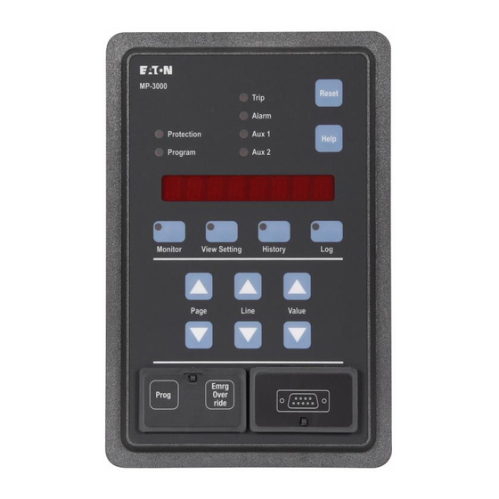
MP-3000 Motor Protection Relay
Instruction Leaflet for Installing, Operating, and Maintaining the
Eaton MP-3000 Motor Protection Relay
IM02602002E
www.eaton.com
Table of
Contents
Previous
Page
Next
Page
1
2
3
4
5
Advertisement
Table of Contents
Troubleshooting
SECTION 12 - TROUBLEShOOTING
83
Troubleshooting the MP-3000
84
Need help?
Do you have a question about the MP-3000 and is the answer not in the manual?
Ask a question
Questions and answers
Related Manuals for Eaton MP-3000
Relays Eaton Cutler-Hammer MP-3000 Manual
Motor protection relay (123 pages)
Relays Eaton MP-3000 Instruction Leaflet
Cutler-hammer motor protection relay (103 pages)
Relays Eaton MP3010 Instruction Leaflet
Motor protection relay (100 pages)
Relays Eaton MP-4000 Instruction Bulletin For Installing, Operating, And Maintaining
Motor protection relay (112 pages)
Relays Eaton Moeller ZEV Series Installation Instructions Manual
Motor-protective system (42 pages)
Relays Eaton MCS Series Instruction Leaflet
(6 pages)
Relays Eaton MPCV Series Instruction Booklet
Network protection relay (32 pages)
Relays Eaton easyE4 Manual
(879 pages)
Relays Eaton D64RP410 Manual
Grownd fault relay (15 pages)
Relays Eaton easyE4 series Manual
(622 pages)
Relays Eaton ZB12/XTOB BC1 Series Manual
Motor-protective relays, overload monitoring of ex e motors (93 pages)
Relays Eaton easy800 Manual
Control relay (394 pages)
Relays Eaton ESR5-VE3-42 Manual
Safety relay (27 pages)
Relays Eaton Power Xpert C445 User Manual
Global motor management relay (436 pages)
Relays Eaton Cutler-Hammer Digitrip 3000 Instructions For Installation, Operation And Maintenance
Protective relay (92 pages)
Relays Eaton EDR-5000 Nstallation, Operation And Maintenance Manual
Distribution (1041 pages)
This manual is also suitable for:
Mp3010
Mp3010incom
Mp3010modbus
Mp3010devicen
Mp3110
Mp3110incom
...
Show all
Mp3110modbus
Mp3110devicen
Mp3011
Mp3012
Mp3013
Mp3014
Mp3111
Mp3112
Mp3113
Mp3114
Mp3010vpi
Mp3010vpm
Mp3010vpd
Mp3110vpi
Mp3110vpm
Mp3110vpd
Table of Contents
Print
Rename the bookmark
Delete bookmark?
Delete from my manuals?
Login
Sign In
OR
Sign in with Facebook
Sign in with Google
Upload manual
Upload from disk
Upload from URL


Need help?
Do you have a question about the MP-3000 and is the answer not in the manual?
Questions and answers