
Related Manuals for Eaton MP-4000


Summary of Contents for Eaton MP-4000
- Page 1 IB02602002E Rev. F MP-4000 Motor Protection Relay Instruction Bulletin for Installing, Operating, and Maintaining the Eaton MP-4000 Motor Protection Relay IB02602002E www.eaton.com...
- Page 2 DOCUMENT SHALL NOT BECOME PART OF OR MODIFY ANY CONTRACT BETWEEN THE PARTIES. In no event will Eaton be responsible to the purchaser or user in contract, in tort (including negligence), strict liability or otherwise for any special, indirect, incidental, or consequential damage or loss whatsoever, including but not lim-...
-
Page 3: Table Of Contents
Page 24, SP2 AUX 2, Settings P24L1 to L7..............................5-14 5.25 Page 25, SP2 SYS, P25L1 to L9, WATT Hours Display ...........................5-15 5.26 Page 26, SP COMM Settings for RS232 Communications ........................5-15 SECTION 6 - INSTallaTION aND WIRING ................................6-1 Mounting the MP-4000 Motor Protection Relay ............................6-1 Wiring - General Information ..................................6-1 www.eaton.com Page... - Page 4 11.10 Checking Discrete Input 1 ..................................11-2 11.11 Checking Discrete Input 2 ..................................11-2 11.12 Verify Voltage Inputs....................................11-2 SECTION 12 - TROUBlEShOOTING ..................................12-1 12.0 General........................................12-1 12.1 Panel Operations.......................................12-1 12.2 Troubleshooting MP-4000 Monitored Equipment ............................12-1 12.3 Troubleshooting the MP-4000 ...................................12-2 12.4 Technical Assistance ....................................12-2 Page www.eaton.com...
- Page 5 MP-4000 IB02602002E SECTION 13 - DRaWOUT CaSE OPTION FOR ThE MP-4000 MOTOR PROTECTION RElay ................13-1 13.0 Introduction........................................13-1 13.1 General Description....................................13-1 13.2 Installation .........................................13-1 13.3 Wiring and Setup .......................................13-2 13.4 Application Considerations ..................................13-2 13.5 Drawout Operation ....................................13-4 13.6 Warranty and Liability Information ................................13-4 13.7 Technical Assistance ....................................13-4 www.eaton.com Page...
- Page 6 IB02602002E MP-4000 This Page Intentionally Left Blank Page www.eaton.com...
-
Page 7: Section 1 - Introduction
MP-3000. The cutout and mounting are compatible. The relay termi- nal configuration and wiring connections are similar. When replacing The MP-4000 protects 50 or 60 Hz three-phase motors of any size or voltage level. It can protect induction or synchronous motors, with or the IQ 1000 II or MP-3000 with the MP-4000, additional terminals are without RTDs. -
Page 8: Use Of This Manual
17. Emergency override function resets jogging limit functions and Once the User is familiar with the basics of operating the MP-4000, clears thermal-model bucket to permit restart with a time-tagged Tables 4.1 through 4.5 can be used as guides to program and monitor event log. - Page 9 MP-4000 IB02602002E Table 1.2 MP-4000 Motor Protection Relay Ordering Information. Catalog Number Style Number Description MP4010 Fixed Case, 5A CT 66D2206G01 Fixed Case, 5A CT, with INCOM Communications MP4010INCOM 66D2206G02 Fixed Case, 5A CT, with Modbus Communications MP4010MODBUS 66D2206G03 Fixed Case, 5A CT, with DeviceNet Communications MP4010DEVICEN...
- Page 10 IB02602002E MP-4000 Table 1.3 MP-4000 Motor Protection Relay accessories. Catalog Number Style Number Description URTD Module Universal RTD Module 2D78559G01 IQ DC dc to ac power supply converter, 100 - 150 Vdc IQDCPS 66C2462G01 1 Meter precut optical fiber link for URTD with connectors MPFO-1 66D2037G01...
-
Page 11: Section 2 - Product Overview
Pickup, start and run timers, and separate alarm settings are provided. The MP-4000 has two discrete inputs, four form C (1 N.O. and 1 N.C.) output contacts, and one 4 to 20 mA analog output. The relay lets the 2.1.4 Ground Fault Protection... -
Page 12: Motor Starting And Control Functions
Separate alarm functions are also load current for greater than the locked rotor time. The MP-4000 has a timing feature that holds off thermal tripping during the long accel- provided. -
Page 13: Section 3 - Mp-4000 Technical Specifications
MP-4000 IB02602002E SECTION 3 - MP-4000 TEChNICal SPECIFICaTIONS Motor Overload Protection (I Full Load Amps: 10 to 3,000 A Locked Rotor Current: 300 to 1,200% FLA Control Power Locked Rotor Time: 1 to 120 sec. Nominal Voltage: 120 Vac or 240 Vac Ultimate Trip Current: 85 to 150% FLA (+10%, –25%) - Page 14 IB02602002E MP-4000 alarm Setting Range IPONI Communications (Section 10 contains more protocols.) Ground Fault: Off, 2% to 55% CT Ratio Type: 2-wire, 115.2 kHz carrier Off, 60 to 99% I Baud Rate: 1,200 ASK or 9,600 FSK Overload I Jam: Off, 100 to 1,200% FLA Max.
-
Page 15: Section 4 - Operator Panel
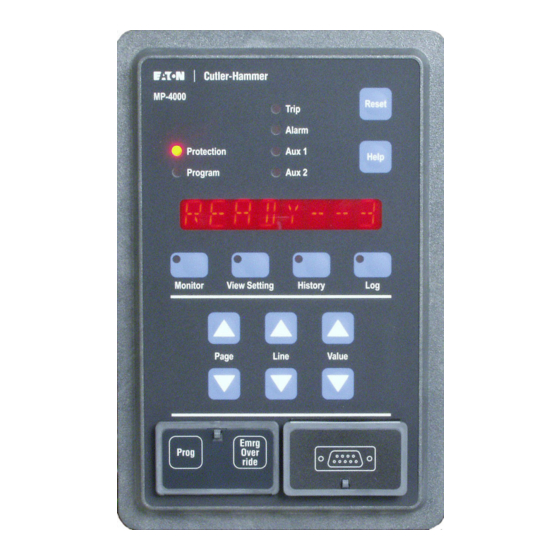
There are 10 LEDs on the operator panel. 4.0 General Description The Protection LED is lit when the MP-4000 is in the Protection mode. The faceplate of the MP-4000 contains the display, indicators, and The MP-4000 provides protection when the relay is in the Program pushbuttons that make up the Operator Panel (Figures 4.1 and 4.2). -
Page 16: Monitor Mode
IB02602002E MP-4000 the new state flashes on the display for five seconds, and the display 4.4 history Mode returns to the value being monitored. Pressing the History mode pushbutton displays the past history of the 4.2 Monitor Mode motor as listed in Table 4.4. - Page 17 MP-4000 IB02602002E Reset Help Display View Setting Mode Monitor Log Mode Page History Mode Line Value RS-232 Connector Program Mode Security Door Figure 4.1 MP-4000 Pushbuttons. Auxiliary 1 Trip Alarm Protection Program Auxiliary 2 Monitor History Mode View Setting Figure 4.2 MP-4000 lED Indicators. www.eaton.com Page...
- Page 18 READY--1 READY TO START MOTOR, SINGLE WaRNING PHASE TEST MODE MP-4000 has been set to 1 PHASE for bench testing only. Will not protect a 3-phase motor. Change setting P13L1 to 3 PHASE for normal motor protection. READY--3 READY TO START MOTOR, THREE Motor is stopped and MP-4000 is ready for a start, 3-phase mode.
- Page 19 AUXILIARY TEMP IN DEGREES F or C RTD reading - terminals 33, 34, 35. MONT REAL TIME MOTOR DATA Motor monitoring data follows. MP-4000 software version in use. VER XXXX SOFTWARE VERSION NUMBER Percentage of thermal bucket used. %I2T XXX...
- Page 20 IB02602002E MP-4000 Table 4-2. Monitor Mode Display. SUB- LINE DISPLAY COMPLETE HELP MESSAGE DESCRIPTION MENU MONT REAL-TIME DATA FROM CURRENT PHASOR MEASUREMENTS Phase A current magnitude. IAMG XXXX IA PHASOR MAGNITUDE Phase B current magnitude. IBMG XXXX IB PHASOR MAGNITUDE Phase C current magnitude.
- Page 21 MP-4000 IB02602002E Program Date Control Schematic Unit ID/Starter Type Work Order # Motor HP Mfgr. Serial # Volts Stall Time/LRT Accel. Time RTD Type Other Table 4-3. View Setting Mode/Program Worksheet. SUB- LINE # DISPLAY HELP MESSAGE SETTING RANGE/VALUE VALUE SELECTED MENU (DEFaUlT SElECTION aND ValUE aS ShIPPED IN BOlD) VIEW SP...
- Page 22 IB02602002E MP-4000 Table 4-3. View Setting Mode/Program Worksheet. SUB- LINE # DISPLAY HELP MESSAGE SETTING RANGE/VALUE VALUE SELECTED MENU (DEFaUlT SElECTION aND ValUE aS ShIPPED IN BOlD) GFSD XX GROUND FAULT START DELAY IN (5) 2-60 ac cycles (1 cycle increments) CYCLES GFRD XX GROUND FAULT RUN DELAY IN CYCLES (2)
- Page 23 MP-4000 IB02602002E Table 4-3. View Setting Mode/Program Worksheet. SUB- LINE # DISPLAY HELP MESSAGE SETTING RANGE/VALUE VALUE SELECTED MENU (DEFaUlT SElECTION aND ValUE aS ShIPPED IN BOlD) INSQ XXX INCOMPLETE SEQUENCE REPORT 1-240 sec., OFF (1 sec. increments) BACK TIME IN SECONDS ON DISCRETE INPUT 2 NOTE: Choosing a time value here (not OFF) also locks P7L1 to INC SEQ and no other choices are available there.
- Page 24 IB02602002E MP-4000 Table 4-3. View Setting Mode/Program Worksheet. SUB- LINE # DISPLAY HELP MESSAGE SETTING RANGE/VALUE VALUE SELECTED MENU (DEFaUlT SElECTION aND ValUE aS ShIPPED IN BOlD) Choose: ENABLE PHASE UNBALANCE ALARM UB a ON Toggles between , UB T ON, and UB A ON OR TRIP TO ACTIVATE ALARM RELAY UB OFF...
- Page 25 MP-4000 IB02602002E Table 4-3. View Setting Mode/Program Worksheet. SUB- LINE # DISPLAY HELP MESSAGE SETTING RANGE/VALUE VALUE SELECTED MENU (DEFaUlT SElECTION aND ValUE aS ShIPPED IN BOlD) PaGE 9, SP aUX 1 SETTINGS FOR aUX 1 RElay OUTPUT CONFIGURaTION LSPU XXX LOAD SHED PICK-UP CURRENT AS 50-150%, (1% increments) % OF FLA NOTE: P9L1 and P9L2 are forced to be coherent. Refer to Section 5 for details.
- Page 26 IB02602002E MP-4000 Table 4-3. View Setting Mode/Program Worksheet. SUB- LINE # DISPLAY HELP MESSAGE SETTING RANGE/VALUE VALUE SELECTED MENU (DEFaUlT SElECTION aND ValUE aS ShIPPED IN BOlD) RCOM ON ENABLE RTD MODULE RCOM OFF Toggles between RCOM ON and COMMUNICATION FAILURE TO RCOM OFF ACTIVATE AUX1 RELAY OUTPUT OR DISABLE IOCT ON...
- Page 27 MP-4000 IB02602002E Table 4-3. View Setting Mode/Program Worksheet. SUB- LINE # DISPLAY HELP MESSAGE SETTING RANGE/VALUE VALUE SELECTED MENU (DEFaUlT SElECTION aND ValUE aS ShIPPED IN BOlD) Choose: ENABLE MOTOR BEARING ALARM OR Toggles between MB A ON, MB T ON, and MB A ON TRIP TO ACTIVATE AUX2 RELAY MB OFF...
- Page 28 IB02602002E MP-4000 Table 4-3. View Setting Mode/Program Worksheet. SUB- LINE # DISPLAY HELP MESSAGE SETTING RANGE/VALUE VALUE SELECTED MENU (DEFaUlT SElECTION aND ValUE aS ShIPPED IN BOlD) PaGE 12, SP SyS SETTINGS FOR SySTEM CONFIGURaTION TP MODE X CONFIGURE TRIP RELAY OUTPUT TO TP MODE2 Toggles between TP MODE 1 and BE MODE 1 -- TRIP RELAY ENERGIZES ON TRIP...
- Page 29 MP-4000 IB02602002E Table 4-3. View Setting Mode/Program Worksheet. SUB- LINE # DISPLAY HELP MESSAGE SETTING RANGE/VALUE VALUE SELECTED MENU (DEFaUlT SElECTION aND ValUE aS ShIPPED IN BOlD) TRP ENER TRP ENER - ENERGIZE TRIP RELAY Toggles between TRP ENER and TRP DENR TRP DENR - DE-ENERGIZE TRIP RELAY Reset button to perform...
- Page 30 IB02602002E MP-4000 Table 4-3. View Setting Mode/Program Worksheet. SUB- LINE # DISPLAY HELP MESSAGE SETTING RANGE/VALUE VALUE SELECTED MENU (DEFaUlT SElECTION aND ValUE aS ShIPPED IN BOlD) button, ENG RST ENG RST - PUSH RAISE TO ENABLE Reset Change to PUSH RST and press ENERGY RESET PUSH RST PUSH RST - PUSH RESET TO EXECUTE...
- Page 31 MP-4000 IB02602002E Table 4-3. View Setting Mode/Program Worksheet. SUB- LINE # DISPLAY HELP MESSAGE SETTING RANGE/VALUE VALUE SELECTED MENU (DEFaUlT SElECTION aND ValUE aS ShIPPED IN BOlD) OVA XXXX OVERVOLTAGE MAIN ALARM Main over voltage alarm (59 M-2) 10 - 150 V THRESHOLD OVARXXXX.X OVERVOLTAGE MAIN ALARM RUN Main over voltage alarm (59 M-2) time delay DELAY (0.1 sec.
- Page 32 IB02602002E MP-4000 Table 4-3. View Setting Mode/Program Worksheet. SUB- LINE # DISPLAY HELP MESSAGE SETTING RANGE/VALUE VALUE SELECTED MENU (DEFaUlT SElECTION aND ValUE aS ShIPPED IN BOlD) LGPFE XXXX LAGGING POWER FACTOR ALARM Power factor (55) alarm enable or disable select ENABLE OR DISABLE lagging ( PFLGA XXXX LAGGING POWER FACTOR ALARM...
- Page 33 MP-4000 IB02602002E Table 4-3. View Setting Mode/Program Worksheet. SUB- LINE # DISPLAY HELP MESSAGE SETTING RANGE/VALUE VALUE SELECTED MENU (DEFaUlT SElECTION aND ValUE aS ShIPPED IN BOlD) Choose: ENABLE UNDERPOWER ALARM OR UP OFF Toggles between UP T ON, UP A ON, UP A ON TRIP TO ACTIVATE AUX1 RELAY UP T ON...
- Page 34 IB02602002E MP-4000 Table 4.4 history Mode Display. PAGE LINE DISPLAY COMPLETE HELP MESSAGE DESCRIPTION HIST HISTORY OF MOTOR STATISTICS Number of motor starts logged since last reset. OCNT XX OCNT XX OPERATION COUNT SINCE LAST RESET MM/DD/YY DATE OF RESET Date when OCNT was reset.
- Page 35 MP-4000 IB02602002E Table 4.4 history Mode Display. PAGE LINE DISPLAY COMPLETE HELP MESSAGE DESCRIPTION Total number of I2T trips that occurred I2TT XX I2TT XX NUMBER OF I2T TRIPS SINCE LAST RESET since reset. Date when I2T trip function was reset. MM/DD/YY DATE OF RESET HH:MM:SS Time when I2T trip function was reset.
- Page 36 IB02602002E MP-4000 Table 4.4 history Mode Display. PAGE LINE DISPLAY COMPLETE HELP MESSAGE DESCRIPTION Total number of INCOM remote trips that occurred since reset. INCT XX INCT XX NUMBER OF INCOM REMOTE TRIPS SINCE LAST RESET Date when INCOM remote trip function was reset.
- Page 37 MP-4000 IB02602002E Table 4.4 history Mode Display. PAGE LINE DISPLAY COMPLETE HELP MESSAGE DESCRIPTION Date when ground fault alarms function was reset. MM/DD/YY DATE OF RESET HH:MM:SS Time when ground fault alarms function was reset. TIME OF RESET Total number of I2T alarms that occurred since last reset.
- Page 38 IB02602002E MP-4000 Table 4.4 history Mode Display. PAGE LINE DISPLAY COMPLETE HELP MESSAGE DESCRIPTION HH:MM:SS Time when voltage unbalance failure alarms function was reset. TIME OF RESET Total number of over frequency alarms that occurred since last reset. OF A XX OF A XX...
- Page 39 CLEARED A TRIP OR ALARM communications network. Date that event occurred. MM/DD/YY DATE OF LOGGED EVENT TRIP BYPASS < JUMPER BYPASS OF TRIP MP-4000 TRIP RELAY > BYPASS Date that event occurred. MM/DD/YY DATE OF LOGGED EVENT Time that event occurred. HH.MM.SS...
- Page 40 IB02602002E MP-4000 Table 4-5. log Mode Display. SUB- LINE DISPLAY COMPLETE HELP MESSAGE DESCRIPTION MENU RTD temperatures at time of trip. WT4 XXX WINDING TEMP 4 IN DEGREES (F OR C) AT TIME OF EVENT RTD temperatures at time of trip. WT5 XXX WINDING TEMP 5 IN DEGREES (F OR C) AT TIME OF EVENT RTD temperatures at time of trip.
-
Page 41: Section 5 - Programming The Mp-4000
Open the front panel security door and press the Prog(ram) pushbut- than this value. Remember the Stop Current Threshold is ton to place the MP-4000 into the Program mode (see Figure 4.1). programmed as a percentage of the PCT. For comparison, Table 4.3 can be used as both a guide and a worksheet for program-... - Page 42 For example, a set of three 400:5 phase CTs might be used with an MP-4000 specified for 5 A CTs. The phase CT ratio is then set to 400. For normal use, set UTC to the service factor times 100%. The avail- Alternatively, a set of three 400:1 CTs could be used with an MP-4000 able range is 85% to 150%.
-
Page 43: Sp Rtd, Settings P2L1 To P2L10
5.1.7 Setting P1l7, Frequency (FREQ) Input 11 is an auxiliary general-use input. FREQ sets the MP-4000 for either a 60 Hz or 50 Hz ac supply All RTD inputs have alarm and trip values set below. But, note that frequency. The device assumes the supply and phase currents are only the maximum of the values read via stator RTD channels 1 at the same nominal frequency. -
Page 44: Sp Trip, Settings P3L1 To P3L14
5.2.6 Setting P2l6, load Bearing Trip (lB T) Assume the MP-4000 jam trip function (see Subsection 5.3.6) is set for P2L6 specifies the load bearing temperature limit above which either of a start delay of 15 seconds and a run delay of 5 seconds. If the motor the two load bearing RTDs causes the relay to trip the motor. -
Page 45: Sp Alarm, Settings P4L1 To P4L8
P3L9 sets the current level in percentage of FLA below which the alarm functions are enabled, in power cycles. Use this to block GFT MP-4000 determines that the motor has lost its load and trips the mo- operation until the ground current of power factor correction capacitors tor. -
Page 46: Sp Start, Settings P5L1 To P5L12
Sets the current limit in percent of FLA at which the jam alarm picks up. time between starts is enforced. The MP-4000 treats a start as the first This alarm can be set to OFF. JMA is set to a lower level than the jam in a sequence of cold starts if the motor has been stopped for at least trip level P3L6. -
Page 47: Sp Di 1
Connect the zero 5.5.8 Setting P5l8, Incomplete Sequence Report Back Time speed switch contact to MP-4000 Discrete Input 1. If the contact fails to (INSQ) open within LRT/2 (one-half of locked-rotor time setting P1L3) after a start, the relay trips with a zero speed switch trip message. -
Page 48: Sp Di 2
Incomplete sequence trip; MTR STOP - Motor Stop Detection Blocking - With this setting, a • voltage input to DI 1 keeps the MP-4000 in the RUN mode, even when Remote trip (via discrete input); • the motor current drops below 100 mA secondary. This feature is used Differential trip;... -
Page 49: Sp Aux2, Settings P10L1 To P10L23
MP-4000 is de-energized. ThE OPERaTING SPECIFICS OF ThE TRaNSITION FUNCTION MUST BE CONFIGURED ON ThE SP STaRT PaGE 5, SETTINGS The MP-4000 is normally set for Mode 2 operation of the TRIP and P5l5 TO P5l9, IF ThE TRaNSITION FUNCTION IS SET ON hERE ALARM relays. WITh P10l1. - Page 50 The override can also delay an impending thermal trip of a running motor. The emergency override P12L16 selects the action to take if any of the MP-4000 internal back- action is counted in the history record, and noted with its time tag in the ground self-monitoring programs detect a problem with the relay.
-
Page 51: Sp Test, Settings P13L1 To P13L8
MP-4000 IB02602002E selected, the MP-4000 still displays all alarms and trips, but the trip Stop the motor first. The test is blocked if the motor is running. output relay contact remains in its non-tripped state. Determine whether the MP-4000 trip relay is configured for For safety purposes when the unit is DISARMED, the MP-4000 scrolls MODE 1 or MODE 2 operation. -
Page 52: Spvutrp, Settings P15L1 To P15L7
P16L1 sets the value (in Hz) below which the under frequency trip function begins to time out. 5.18.2 Setting P18l2, Over Voltage Main Trip Threshold (OVT) 5.16.2 Setting P16l2, Under Frequency Trip alarm Start Delay P18L2 sets the voltage threshold (in volts) above which the MP-4000 (UFSD) trips. P16L2 sets the number of seconds after a start until the under fre- 5.18.3 Setting P18l3, Over Voltage Main Run Delay (OVTR) -
Page 53: Sp Uvtrp, Settings P19L1 To P19L7
5.19.2 Setting P19l2, Main Undervoltage Threshold (UVT) 5.21.2 Setting P21l2, leading Power Factor Trip Threshold (PFlDT) P19L2 sets the voltage level (in volts) below which the MP-4000 trips. P21L2 sets the trip threshold for the Leading Power Factor Trip 5.19.3 Setting P19l3, Main Undervoltage Trip Run Delay (UVTR) Threshold. P19L3 sets the number of seconds that the voltage must remain be- 5.21.3 Setting P21l3, lagging Power Factor Trip Enable or... -
Page 54: Arel, Settings P22L1 To L7
IB02602002E MP-4000 5.21.9 Setting P21l9, lagging Power Factor alarm Enable 5.23 Page 23, SP UPTRP, Settings P23l1 to P23l7 Disable (lGPFE) 5.23.1 Setting P23l1 P21L19 enables or disables the Lagging Power Factor Alarm function. P23L1 allows the Voltage Unbalance Alarm or Trip to activate the AUX 1 Relay Output. This function can be disabled by setting this 5.21.10 Setting P21l10, lagging Power Factor alarm Threshold 2... -
Page 55: Sp2 Sys, P25L1 To L9, Watt Hours Display
P26L1 enables (on) or disables (off) the RS-232 communications 5.25.3 Setting P25l3, Volt-amps Display mode. Note that URTD and PONI communications are disabled when P25L3 sets the volt-amps display to kilo, mega, or giga. the MP-4000 is in the RS-232 mode. www.eaton.com Page 5-15... - Page 56 IB02602002E MP-4000 This page intentionally left blank Page 5-16 www.eaton.com...
-
Page 57: Section 6 - Installation And Wiring
PONI, or D-PONI. An E-PONI is 0.5 in. (12.7 mm) deeper. 6.0 Mounting the MP-4000 Motor Protection Relay The PONI, if used, is always mounted on the back of the MP-4000. If no URTD is mounted there, use the mounting bracket supplied with The following subsections describe the mounting of the MP-4000 mo- the MP-4000, as shown in Figure 6.4. - Page 58 MP-4000 are 120 Vac nominal. The voltage inputs are clamped at 220 Vac. Continuous voltages above this level should 6 VA. Do not attempt to power the URTD from the MP-4000 120 Vac discrete source. That source is for contact reading only, and cannot never be applied to the MP-4000, and may result in failure of the unit.
- Page 59 Terminals 24 and 25 provide an isolated source of dc current between necessary to connect both. If both are connected, the MP-4000 uses 4 and 20 mA, the exact value indicating an internal MP-4000 measure- data from the optical fiber. It defaults to the wired connection, only if ment.
- Page 60 IB02602002E MP-4000 Figure 6.2 Panel Cutout Dimensions. Page www.eaton.com...
- Page 61 MP-4000 IB02602002E 6.72 [17.07CM] 0.50 [1.27CM] MP-4000 Reset Trip Alarm Protection Aux 1 Help Program Aux 2 10.25 [26.04CM] Monitor View Setting History Page Line Value Emrg Prog Over ride DIMENSIONS IN INCHES [CM] Figure 6.3 Faceplate Dimensions. www.eaton.com Page...
- Page 62 IB02602002E MP-4000 DIMENSIONS IN INCHES [CM] Figure 6.4 MP-4000 Case Depth Dimensions. Page www.eaton.com...
- Page 63 MP-4000 IB02602002E DIMENSIONS IN INCHES [CM] Figure 6.5 Universal RTD Module Mounting Dimensions. www.eaton.com Page...
- Page 64 IB02602002E MP-4000 Figure 6.6 Rear Panel Terminals. Page www.eaton.com...
- Page 65 MP-4000 IB02602002E Figure 6.7 MP-4000 Typical CT & PT Circuits and Motor Control Wiring. Note: Voltage Inputs Are 120 Nominal, Limited to 150 Vac. Figure 6.8 MP-4000 Typical CT & PT Circuits and Motor Control Wiring (WyE-WyE). www.eaton.com Page...
- Page 66 IB02602002E MP-4000 Figure 6.9 MP-4000 Typical CT and PT Circuits and Motor Control Wiring (Open Delta). Figure 6.10 Typical aC Supply and URTD Wiring. Page 6-10 www.eaton.com...
- Page 67 MP-4000 IB02602002E Figure 6.11 alternatives for Discrete Input Wiring. www.eaton.com Page 6-11...
- Page 68 IB02602002E MP-4000 UNIVERSAL RTD MODULE TERMINALS CABLE RTD TERMINALS SHIELD CABLE SHIELD WIRE RTD WIRING (TWO-LEAD TYPE) RTD WIRING (THREE-LEAD TYPE) NOTES: 1. CONNECT CABLE SHIELD AT RTD MODULE TERMINALS ONLY. . CUT SHIELD SHORT AT MOTOR END AND USE SHRINK TUBING OR ELECTRICAL TAPE TO INSULATE ..
-
Page 69: Section 7 - Startup
DURES. FaIlURE TO COMPly CaN RESUlT IN SERIOUS OR If the optional URTD module is to be powered from terminals FaTal INjURy aND/OR EQUIPMENT DaMaGE. 4 and 7 of the MP-4000, the supply must be 120 Vac only. The URTD is rated only for 120 Vac, and cannot operate CaUTION from 240 Vac. If necessary, use an auxiliary 240 V/120 V step-down transformer for the URTD, able to handle a 6 VA burden. -
Page 70: Further Checking Of The Relay With Ac Power
View SP mode button. the normal state. Reconfirm that the motor nameplate values agree with the Use the MP-4000 discrete input test page indications to test corresponding relay settings. the actual operation of the contacts, if possible. Reconfirm that the ratios of the phase and ground CTs in the gear agree with the PCT and GCT settings of the relay. -
Page 71: Checking The Complete Motor Drive System
PowerNet display. display reads READY - 3. • It is wise to verify the ability of the MP-4000 to open the Follow any startup procedures for the load equipment. contactor and trip the motor. The easiest way is by remote trip, via remote trip contact or data communications. - Page 72 IB02602002E MP-4000 This Page Intentionally Left Blank Page www.eaton.com...
-
Page 73: Section 8 - Motor Thermal Protection Basics
From these samples, the MP-4000 computes RMS currents and average currents. It also performs phasor calculations The MP-4000 has four output relays. The Trip relay is connected in se- leading to direct and precise measurement of positive and negative sequence currents. - Page 74 C phasor 240 degrees in the negative direction. See Figure 8.2.3 Thermal Bucket 8.5. The formula for I The MP-4000 models heating as the filling of a thermal reservoir or accumulating bucket whose size is determined by the thermal capac- -120°) + (I - 240°)
- Page 75 MP-4000 IB02602002E Figure 8.1 Motor Phase Currents from Three Main Motor Phase CTs. Figure 8.2 Torques from Sequence Currents. Figure 8.3 Unbalanced Motor Current Example. www.eaton.com Page...
- Page 76 MP-4000 IB02602002E Figure 8.4 Positive Sequence Component Calculation. Figure 8.5 Negative Sequence Component Calculation. Page www.eaton.com...
-
Page 77: Section 9 - Applications And Settings
Use this data in conjunction with Section 5 and Table 4.3 to develop starting until the temperature, as reflected in the thermal accumulator settings for the MP-4000, as well as to make appropriate wiring de- bucket level, cools below the alarm level setting I2TA, P4L2. - Page 78 TER alSO CONTaINS FUSES, WhICh CaN INTERRUPT ThESE Underload Jam Protection Curve example in Figure 9.3. Here, the FaUlT CURRENTS. underload trip is set at 60% of FLA. The MP-4000 has settings for un- derload alarm (ULA, P4L5), and underload trip (ULT, P3L9). Each can ThE MP-4000 TRIP COMMaND IS INTENDED TO OPEN all be disabled by setting it to OFF. These would be represented by two ThREE PhaSES VIa ThE CONTaCTOR aND BlOCK FURThER such vertical lines, both below the normal load current.
- Page 79 The MP-4000 stores the last four starting current profiles. This profile 9.1.5 load Shedding Function data cannot be read on the front panel display. In some applications, the MP-4000 can forestall a jam alarm or trip, or a thermal trip, by sending a signal to the process to reduce loading. 9.1.8 Thermal Protection by Direct Measurement...
-
Page 80: Motor Cycle Monitoring
Initially, the motor is stopped and the return is normally made from the neutral of the secondary wire winding current is zero. As long as the MP-4000 is not in a trip state, it permits of the supply power transformer. Resistance grounding is acceptable,... -
Page 81: Ac Line Interruptions
User to start the motor. If the current fails to • Under frequency start delay (UFSD, P16L2); stop when the MP-4000 trips a running motor, it may be because of a • Over frequency start delay (OFSD, P17L2);... - Page 82 MP-4000 For a complete supply interruption, the nominal ride-through rating is The MP-4000 declares a motor stop after about 20 cycles of no current. 13 cycles. The relay typically continues to operate for 13 to 20 power The only way to extend this time is to assign the MOTOR STOP func-...
- Page 83 MP-4000 IB02602002E Figure 9.1 Rotor Temperature Tracking. www.eaton.com Page...
- Page 84 IB02602002E MP-4000 Figure 9.2 Motor Protection Curve. Page www.eaton.com...
- Page 85 MP-4000 IB02602002E Figure 9.3 Underload jam Protection Curve. www.eaton.com Page...
- Page 86 IB02602002E MP-4000 Figure 9.4 Motor Protection Curve Example (without RTDs). Page 9-10 www.eaton.com...
- Page 87 MP-4000 IB02602002E Figure 9.5 Motor Protection Curve Example (with RTDs). www.eaton.com Page 9-11...
- Page 88 IB02602002E MP-4000 Figure 9.6 Motor Start and Run Cycles. Page 9-12 www.eaton.com...
-
Page 89: Section 10 - Data Communications
Port®, or host software via its communications port and an optional accessory PONI module mounted on or near the back of the unit. Attach the PONI to the back of the MP-4000 using the mounting bracket supplied with the relay. If the URTD module is to be mounted... -
Page 90: Powernet Incom Communications Protocol
PONIs for further information. documentation. PowerNet software is supplied with its own comprehensive instruc- tions, which explain how to access MP-4000 data and control capabili- ties at the host client computer. Figure 10.1 PONI Communications Module. Page 10-2 www.eaton.com... -
Page 91: Section 11 - Testing
• MODE 1 or MODE 2 operation. Refer to SYSTEM Page To test the MP-4000 inputs and outputs, use the SP TEST page in the Setting P12L1. Program mode. Refer to Subsections 5.0 and 5.13 and to Table 4.3 for In MODE 1, the trip relay is normally de-energized. -
Page 92: Checking Discrete Input 1
11.12 Verify Voltage Inputs Use P13L7 to determine if discrete input 1 is on or off. Apply or re- A DVM can be used to verify readings displayed by the MP-4000. Measure voltage between the ground input connection and each move 120 Vac to check both states. -
Page 93: Section 12 - Troubleshooting
100 events, a log of the last 20 abnormal events with more details, and By QUalIFIED PERSONNEl WhO aRE FaMIlIaR WITh ThE MP- a detailed log of the last four starts. The MP-4000 logs motor events in 4000 aND ITS aSSOCIaTED MOTOR aND MaChINES. FaIlURE chronological order with details and time tag as listed in Table 4.5. -
Page 94: Troubleshooting The Mp-4000
If two or more trip conditions occur at the same time, the display If the motor trips or alarms for one of these failures, the MP-4000 must alternates between or among the menu item and the cause be replaced. - Page 95 MP-4000 IB02602002E Table 12.1 alarm Conditions. Display Complete help Message Probable Cause Solution Insulation failure - ground DANGER: Personnel hazard. GND FAULT GROUND FAULT ALARM current leakage. Stop and isolate the motor as soon as possible to avoid more dangerous or damaging fault. Get expert evaluation of motor insulation condition.
- Page 96 IB02602002E MP-4000 Table 12.1 alarm Conditions. Display Complete help Message Probable Cause Solution An under voltage condition UND VOLT UNDERVOLTAGE ALARM occurred. An over frequency condition OVR FREQ OVER FREQUENCY ALARM occurred. An over frequency condition UND FREQ UNDER FREQUENCY ALARM occurred. An under power condition...
- Page 97 • Use DI 2 test to confirm that lay, was not received in time the MP-4000 sees an input. after the start or transition. An interruption (of 20 •Check setting P5L8 against seconds minimum to 40 sec- the process feedback time.
- Page 98 IB02602002E MP-4000 Table 12.2 Trip Conditions. Display Complete help Message Probable Cause Solution Discrete input 1 has been • Make sure this function has ZSW TRIP ZERO SPEED SWITCH INPUT FAILED TO BE set for zero speed switch been intentionally enabled. • If ZSW trip occurs at the FALSE WITHIN 1/2 OF sensing via setting P6L1.
- Page 99 The causes are: • An incoming source has The MP-4000 is set for non- reversing starter; the motor swapped phases. Swap two is never supposed to run of the incoming power leads backwards.
- Page 100 Probable Cause Solution Incoming ac deficient. All LEDs and displays are off or The MP-4000 operates down to 55% of unintelligible. rated voltage, but such a low voltage is not normal and should be diagnosed. Verify that 120 or 240 Vac (±15%) exists between terminals 4 and 7.
-
Page 101: Section 13 - Drawout Case Option For The Mp-4000 Motor Protection Relay
Motor Protection Relay. windings. The basic operation of the MP-4000 relay is applicable to all styles of the drawout case. Table 13.1 lists the Drawout Case versions. An extra set of self-shorting terminals can be used to keep the motor running while the relay is out of its case, or to provide a No Protection Alarm (refer to Subsection 13.4 for more information). -
Page 102: Wiring And Setup
The outputs of the MP-4000 relay can be configured in either Mode 1 or Mode 2 operation. Refer to Subsections 5.12.1 and 6.2.3 for more In each terminal block, wire the lower tier terminals before the information on the functionality of modes 1 and 2. - Page 103 IB02602002E MP-4000 5.380 [136.65] 2.690 [68.33] .062 R AD [1.59] 4 P LAC E S 2.531 [64.29] 0.203 DIA [5.16] 5.062 [128.57] 10 P LAC E S P ANE L C UT OUT DIME NS IONS IN INC HE S [MM] Figure 13.1 Panel Cutout Dimensions.
-
Page 104: Drawout Operation
• Set the INCOM communication device address. In no event will Eaton Inc. be responsible to the purchaser or User in • If the URTD fiber optic cable is used, refer to Subsection contract, in tort (including negligence), strict liability, otherwise for any 13.3.1 for special instructions concerning the proper installa-... - Page 105 IB02602002E MP-4000 DIMENSIONS IN INChES (MM) Figure 13.2 MP-4000 Drawout Panel Mounting. DIMENSIONS IN INChES (MM) Figure 13.3 Rear View of MP-4000 Drawout Outer Case. www.eaton.com Page 13-5...
- Page 106 IB02602002E MP-4000 Figure 13.4 MP-4000 Drawout Typical Circuits and Motor Control Wiring (Direct Connect). Note: Voltage Inputs Are 120 Vac Nominal, Limited to 150 Vac. Figure 13.5 MP-4000 Drawout Typical CT Circuits and Motor Control Wiring (Wye-Wye). Page 13-6 www.eaton.com...
- Page 107 IB02602002E MP-4000 Figure 13.6 MP-4000 Drawout Typical CT Circuits and Motor Control Wiring (Open Delta). www.eaton.com Page 13-7...
- Page 108 IB02602002E MP-4000 Figure 13.7 MP-4000 Drawout Typical aC Supply and URTD Wiring. Figure 13.8 MP-4000 Drawout alternatives for Discrete Input Wiring. Page 13-8 www.eaton.com...
- Page 109 IB02602002E MP-4000 INPUT CONTACTS OR PUSHBUTTONS 120 Vac ONLY REMOTE CONTACT WETTING SUPPLY 41 42 43 44 CONTROL POWER TRANSFORMER 15 16 47 48 120 Vac 49 50 240 Vac 55 56 NON-CURRENT- CARRYING GND Figure 13.9 MP-4000 Drawout alternatives for Discrete Input Wiring. www.eaton.com Page 13-9...
- Page 110 IB02602002E MP-4000 This Page Intentionally Left Blank Page 13-10 www.eaton.com...
- Page 111 MP-4000 IB02602002E This Page Intentionally Left Blank www.eaton.com...
- Page 112 Moon Township, PA 15108-4312 United States 877-ETN-CARE (877-386-2273) Eaton.com © 2012 Eaton Corporation All Rights Reserved Printed in USA Publication No. IB02602002E Rev. F Eaton is a registered trademark of Eaton Style No. 66A2280H05 / TBG000271 Corporation April 2012 www.eaton.com...
Need help?
Do you have a question about the MP-4000 and is the answer not in the manual?
Questions and answers