
Related Manuals for Eaton MP-3000


Summary of Contents for Eaton MP-3000
- Page 1 MP-3000 Motor Protection Relay Instruction Leaflet IL17562C IL17562BH04 For more information visit: www.cutler-hammer.eaton.com Effective 10/02...
-
Page 2: Table Of Contents
SECTION 1—INTRODUCTION ............1-2 Motor Protection ............... 9-1 General ................1-2 Motor Cycle Monitoring ............ 9-4 Replacing the IQ1000 II with MP-3000 ......1-2 AC Line Interruptions ............9-5 MP-3000 Enhancements ..........1-2 SECTION 10—DATA COMMUNICATIONS ........10-1 Use of Manual ..............1-3 10.1... - Page 3 13.5 MP-3000 Drawout Typical Ct Circuits and Motor Control Wiring ............. 13-6 13.6 MP-3000 Drawout Typical AC Supply and urtd wiring ..13-7 13.7a MP-3000 Drawout Alternatives for Discrete Input Wiring ..13-7 13.7b MP-3000 Drawout Alternatives for Discrete Input Wiring ..13-8 IL17562BH04 For more information visit: www.cutler-hammer.eaton.com...
-
Page 4: Section 1-Introduction
• Disarmed mode for commissioning and checking in a running wide range of conditions. process. The MP-3000 protects 50 or 60 Hz three-phase motors of any size or voltage level. It can protect induction or synchronous motors, with or 1.1 Replacing the IQ1000 II with MP-3000 without RTDs. -
Page 5: Use Of Manual
14. Flexible user-configurable inputs and outputs for broader application. Once the user is familiar with the basics of operating the MP-3000, Tables 4.1 through 4.5 serve as guides to program and monitor the MP- 15. New options for transition function control and monitoring on time 3000. -
Page 6: Mp-3000 Motor Protection Relay Ordering Information
Motor relay with 1 A nominal input, fixed case MP3000VPI 66D2036G11 Value Pack includes MP-3000 with 5 A nominal input, URTD, IPONI & Fiber Optic Cable MP3100VPI 66D2036G12 Value Pack includes MP-3000 with 1 A nominal input, URTD, IPONI & Fiber Optic Cable... -
Page 7: Mp-3000 Renewal Parts
Page 1-4 Table 1.3 MP-3000 Renewal Parts Catalog Number Style Number Description MP3001-IC 66D2029G21 MP3001 relay inner drawout chassis, 5A Cts, no communications MP3101-IC 66D2029G23 MP3101 relay inner drawout chassis, 1A Cts, no communications MP3002-IC 66D2029G22 MP3002 relay inner drawout chassis, 5A Cts, IPONI... -
Page 8: Section 2-Product Overview
60 Hz or 50 Hz operation. 2.1.4 Ground Fault Protection The MP-3000 has 2 discrete inputs, 4 form c (1 N.O. and 1 N.C.) output contacts, and one 4 to 20 ma analog output. The relay lets the user A separate measuring circuit is used to measure ground current. -
Page 9: User Interface
The MP-3000 has a expected action doesn’t occur. timing feature which holds off thermal tripping during the long acceleration. -
Page 10: Section 3-Mp3000 Technical Specifications
Page 3-1 SECTION 3—MP-3000 TECHNICAL SPECIFICATIONS Trip Setting Ranges Ground fault (GF): Off, 2% to 55% of Ct ratio Control Power primary Nominal voltage: 120 Vac or 240 Vac GF start delay: 2 to 60 cycles (+10%, -25%) GF run delay:... - Page 11 Read/write set points UL Standard: 1053, Ground Fault Protective Device Read metered values ANSI: C37.90, C37.90.1, Read trip/alarms and C37.90.2 Read events Read history Reset history Reset functions Emergency override Trip View Starting Profile IL17562BH04 For more information visit: www.cutler-hammer.eaton.com Effective 10/02...
-
Page 12: Section 4-Operator Panel
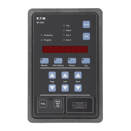
There are 10 LEDs on the operator panel. 4.0 General Description The Protection LED is lit when the MP-3000 is in the Protection mode. The faceplate of the MP-3000 contains the display, indicators, and The MP-3000 provides protection with the relay while in the Program pushbuttons that make up the Operator Panel (Figures 4.1 and 4.2). -
Page 13: View Settings And Program Mode
Refer to the examples given for the History mode in Section 4.4 on the Pressing the History mode displays the past history of the motor as use of the navigation buttons. shown in Table 4.4. Fig. 4.1 MP-3000 Pushbuttons IL17562BH04 For more information visit: www.cutler-hammer.eaton.com Effective 10/02... -
Page 14: Mp-3000 Led Indicators
READY—1 READY TO START MOTOR, SINGLE WARNING PHASE TEST MODE MP-3000 has been set to 1 PHASE for bench testing only. Will not protect a 3-phase motor. Change setting P13L1 to 3 PHASE for normal motor protection. READY—3 READY TO START MOTOR, THREE Motor is stopped and MP-3000 is ready for a start, 3-phase mode. -
Page 15: Monitor Mode Display
MONT MTR REAL TIME MOTOR DATA Motor monitoring data follows VER XXXX SOFTWARE VERSION NUMBER MP-3000 software version in use %I2T XXX PERCENT OF I2T TRIP LEVEL Percent of thermal bucket used TUS XXX TIME IN MINUTES UNTIL NEXT START... - Page 16 MONT TIM DATE AND TIME Current date and time with display format as programmed. HH.MM XM CURRENT TIME 12-hour format HH.MM 24-hour format MM/DD/YY CURRENT DATE Common format DD/MM/YY European / military format Effective 10/02 For more information visit: www.cutler-hammer.eaton.com IL17562BH04...
-
Page 17: View Settings Mode/Program Worksheet
5.2.3 390°F, OFF (1°increments) MB T XXX MOTOR BEARING TRIP 0-199°C, OFF / 32- 5.2.4 390°F, OFF (1°increments) MB A XXX MOTOR BEARING ALARM 0-199°C, OFF / 32- 5.2.5 390°F, OFF (1°increments) IL17562BH04 For more information visit: www.cutler-hammer.eaton.com Effective 10/02... - Page 18 UBSD XXX PHASE UNBALANCE TRIP AND ALARM 0-120 sec. (1 sec. 5.3.13 START DELAY IN SECONDS increments) UBTR XXX PHASE UNBALANCE TRIP RUN DELAY 0-240 sec. (1 sec. 5.3.14 IN SECONDS increments) Effective 10/02 For more information visit: www.cutler-hammer.eaton.com IL17562BH04...
- Page 19 TRN T+C – ON TIME OR CURRENT, start-to-run TRN T/C TRN T/C – ON TIME AND CURRENT transition: TRN TIME, TRN I, TRN T+C, or TRN T/C. Refer to settings P5L5 and P5L6. IL17562BH04 For more information visit: www.cutler-hammer.eaton.com Effective 10/02...
- Page 20 ZERO SW and no other choices are available there. Also, setting P6L1 to ZERO SW will force ZSW ON here. ABK XXXX ANTI-BACKSPIN DELAY TIME 1-3600 seconds, 5.5.1.2 IN SECONDS OFF (1 second increments) Effective 10/02 For more information visit: www.cutler-hammer.eaton.com IL17562BH04...
- Page 21 ENABLE JAM ALARM OR TRIP TO Toggles between JAM A JAM A ON ACTIVATE ALARM RELAY OUTPUT OR JAM A ON, JAM T JAM T ON DISABLE ON, and JAM OFF JAM OFF IL17562BH04 For more information visit: www.cutler-hammer.eaton.com Effective 10/02...
- Page 22 PH R ON and PH PH R OFF DISABLE R OFF INSQ ON ENABLE INCOMPLETE SEQUENCE TRIP Toggles between INSQ TO ACTIVATE ALARM RELAY OUTPUT INSQ ON and INSQ OFF OR DISABLE INSQ OFF Effective 10/02 For more information visit: www.cutler-hammer.eaton.com IL17562BH04...
- Page 23 ENABLE I2T ALARM OR TRIP TO Toggles between I2T T ON 5.9.4 I2T A ON ACTIVATE AUX1 RELAY OUTPUT I2T A ON, I2T T I2T T ON OR DISABLE ON, and I2T OFF IL17562BH04 For more information visit: www.cutler-hammer.eaton.com Effective 10/02...
- Page 24 RCOM OFF AUX1 RELAY OUTPUT OR DISABLE RCOM OFF IOCT ENABLE INSTANTANEOUS Toggles between IOCT OFF 5.9.4 OVERCURRENT TRIP TO ACTIVATE IOCT ON and IOCT OFF AUX1 RELAY OUTPUT OR DISABLE IOCT OFF Effective 10/02 For more information visit: www.cutler-hammer.eaton.com IL17562BH04...
- Page 25 JAM OFF Choose: ENABLE UNDERLOAD ALARM OR TRIP Toggles between UL OFF 5.10.2 UL A TO ACTIVATE AUX2 RELAY OUTPUT OR UL A ON, UL T UL T DISABLE ON, and UL OFF IL17562BH04 For more information visit: www.cutler-hammer.eaton.com Effective 10/02...
- Page 26 INSQ ON and INSQ OFF DISABLE INSQ OFF REMT ON ENABLE REMOTE TRIP TO ACTIVATE Toggles between REMT OFF 5.10.2 AUX2 RELAY OUTPUT OR DISABLE REMT ON and REMT OFF REMT OFF Effective 10/02 For more information visit: www.cutler-hammer.eaton.com IL17562BH04...
- Page 27 MAN I2T 5.12.5 MAN I2T and AUTO I2T AUTO I2T RUN PGM ENABLES UNIT TO BE PROGRAMMED Toggles between STOP 5.12.6 WHILE MOTOR IS RUNNING RUN PGM and STOP PGM STOP PGM IL17562BH04 For more information visit: www.cutler-hammer.eaton.com Effective 10/02...
- Page 28 DAY MONTH YEAR IMPACC COMMUNICATIONS MODE Toggles between IQ2 DIS 5.12.15 IQ2 EN – IQ1000II EMULATION IQ2 EN and IQ2 IQ2 DIS – MP-3000 COMMUNICATION RLYF TRP INTERNAL DIAGNOSTIC FAILURE Toggles between RLYF T+A 5.12.16 RLYF ALM ACTIVATES TRIP AND OR ALARM...
- Page 29 TRIP HISTORY RESET RST and press PUSH RST PUSH RST – PUSH RESET TO EXECUTE Reset button, or RESET OF TRIP HISTORY OR PUSH return to TRIP RST RAISE TO NOT RESET IL17562BH04 For more information visit: www.cutler-hammer.eaton.com Effective 10/02...
-
Page 30: History Mode Display
HIGHEST LOAD BEARING Maximum load bearing temperature TEMPERATURE IN DEGREES C(F) monitored since reset MM/DD/YY DATE OF EVENT The date of highest LMX HH:MM:SS TIME OF EVENT The time of highest LMX Effective 10/02 For more information visit: www.cutler-hammer.eaton.com IL17562BH04... - Page 31 TEMPERATURE TRIPS SINCE LAST MM/DD/YY RESETDATE OF RESET HH:MM:SS TIME OF RESET AX T XX AX T XX NUMBER OF AUXILIARY TEMPERA- TURE TRIPS SINCE LAST RESET DATE MM/DD/YY OF RESET HH:MM:SS TIME OF RESET IL17562BH04 For more information visit: www.cutler-hammer.eaton.com Effective 10/02...
- Page 32 TIME OF RESET function was reset The time when respective alarm function was reset I2TA XX I2TA XX NUMBER OF I2T ALARMS SINCE LAST RESET MM/DD/YY DATE OF RESET HH:MM:SS TIME OF RESET Effective 10/02 For more information visit: www.cutler-hammer.eaton.com IL17562BH04...
- Page 33 HISTORY OF TRIP EVENTS TRPS TOTAL NUMBER OF TRIPS SINCE RESET MM/DD/YY DATE OF RESET HH:MM:SS TIME OF RESET TRT XXXX TOTAL RUN TIME SINCE RESET MM/DD/YY DATE OF RESET HH:MM:SS TIME OF RESET IL17562BH04 For more information visit: www.cutler-hammer.eaton.com Effective 10/02...
-
Page 34: Log Mode Display
This can be done through the front face panel “Reset” MM/DD/YY DATE OF EVENT button, by a programmed discrete HH.MM TIME OF EVENT input activation, or over the communi- cation network. Effective 10/02 For more information visit: www.cutler-hammer.eaton.com IL17562BH04... - Page 35 C) AT TIME OF EVENT” WT6 XXX WINDING TEMP 6 IN DEGREES (F OR C) AT TIME OF EVENT” MT1 XXX MOTOR BEARING TEMP 1 IN DEGREES (F OR C) AT TIME OF EVENT IL17562BH04 For more information visit: www.cutler-hammer.eaton.com Effective 10/02...
- Page 36 TIME FROM START TO CURRENT The elapsed time from start to current TRANSITION IN SECONDS below the transition current set point level TSTR XXX TIME FROM START TO RUN OR TRIP IN SECONDS Effective 10/02 For more information visit: www.cutler-hammer.eaton.com IL17562BH04...
- Page 37 Page 4-26 Page 4-26 This page left blank intentionally. IL17562BH04 For more information visit: www.cutler-hammer.eaton.com Effective 10/02...
-
Page 38: Section 5-Programming The Mp-3000
FLA IS A FIXED PROPERTY OF THE MOTOR. SELECT A CT tion, the MP-3000 exits the program mode without actually making WHOSE RATIO IS SUITABLE FOR THIS MOTOR. any of the changes entered to that time. State changes include any transition to start, run, stop, alarm, or trip. -
Page 39: Inconsistent Settings Messages
Figure 9.4. NOTE: This UTC setting is where the user considers the service factor MANY OF THE PROTECTION FUNCTIONS OF THE MP-3000 rating of the motor. Never adjust the FLA setting P1L1 INCLUDING THE MOTOR THERMAL PROTECTION ALGORITHM, according to the service factor (see subsection 9.1.3.3). -
Page 40: Sr Rtd, Settings P2L1 To P2L10
All displayed information is the same for either of the two types of MP- Sets the MP-3000 for either a 60 Hz or 50 Hz ac supply frequency. No 3000 relays. When Ct ratios are to be set, the value entered is the hardware settings are necessary. -
Page 41: Sp Trip, Settings P3L1 To P3L14
C or F depending on Setting P2L1 above. There are two specifically-labeled motor bearing RTD inputs on the URTD module Say the MP-3000 jam trip function (see below) is set for a start delay whose readings can trigger this particular type of alarm. - Page 42 5.3.9 Setting P3L9, Underload Trip Level (ULT) tors decays after a start. Sets the current level in percent of FLA below which the MP-3000 5.3.3 Setting P3L3, Ground Fault Run Delay (GFRD) determines that the motor has lost its load and trips the motor. This element can be set to OFF.
-
Page 43: Sp Alarm, Settings P4L1 To P4L8
Sets the current limit in percent of FLA at which the jam alarm picks between starts is enforced. The MP-3000 treats a start as the first in a up. This alarm can be set to OFF. Set to a lower level than the jam trip sequence of cold starts if the motor has been stopped for at least the level P3L6. - Page 44 ZSW is set to OFF. To use this function, set a time limit for report-back here. Set P5L9, With ZSW ON, the MP-3000 checks Discrete Input 1 for voltage at the next, to define the start of report-back timing. Connect the report- very moment it sees a start—it wants to see the initially closed zero-...
-
Page 45: Sp Di 1
MTR STOP–Motor Stop Detection Blocking—With this setting, a • Phase unbalance alarm, or trip voltage input to DI 1 will keep the MP-3000 in the RUN mode even • Winding temperature alarm, or trip (with URTD) when the motor current drops below 100 mA secondary. This feature •... -
Page 46: Sp Aux2, Settings P10L1 To P10L23
MUST BE CONFIGURED ON THE SP START PAGE 5, SETTINGS opens for a trip, if the MP-3000 power supply is de-energized, or the P5L5 TO P5L9, IF THE TRANSITION FUNCTION IS SET ON HERE product fails. - Page 47 Page 5-10 The MP-3000 is normally set for Mode 2 operation of the TRIP and 5.12.7 Setting P12L7, Emergency Override Enable (EMRG EN or ALARM relays. EMRG DIS) 5.12.2 Setting P12L2, Configure Alarm Relay Output (AL MODE1 or Select if the emergency override button is enabled or disabled. If...
-
Page 48: Sp Test, Settings P13L1 To P13L8
5.12.17 Setting P12L17, INCOM Trip Enabled or Disabled (INCT EN or INCT DIS) Selects whether or not the MP-3000 will accept and execute a motor trip command from a remote PowerNet or IMPACC operator via data communications. This is dictated by security concerns and operating procedures of users who connect the MP-3000 to a facility control system. -
Page 49: Sp Reset, Settings P14L1 To P14L4
• 5.14.2 Setting P14L2, Trip History Reset (TRIP RST) • 5.14.3 Setting P14L3, Alarm History Reset (ALRM RST) • Determine whether the MP-3000 trip relay is configured for MODE 1 • 5.14.4 Setting P14L4, History Totals Reset (TOT RST) or MODE 2 operation - see SYSTEM Page Setting P12L1 •... -
Page 50: Section 6-Installation And Wiring
PONI, or D-PONI. An E-PONI is 0.5 inch deeper. 6.1 Mounting The PONI, if used, is always mounted on the back of the MP-3000. If no URTD is mounted there, use the mounting bracket supplied with the MP- The following subparagraphs describe the mounting of the MP-3000 3000 as shown in Figure 6.3. -
Page 51: Alarm Conditions
If the supply is a dc battery system, use the optional IQ DC power secondary resistance of the Ct itself. The MP-3000 presents very low supply. The IQ DC supply is able to power the MP-3000, the URTD if burden. - Page 52 #16 AWG or #18 AWG. Connect Figure 6.7 shows connections between the URTD and the MP-3000. the cable shield only at the MP-3000 end, at terminal 23. Insulate the Use either the optical fiber or the electrical 3-wire connection. It is not shield and do not connect at the URTD end.
-
Page 53: Panel Cutout Dimensions
Page 6-4 Fig. 6.1 Panel Cutout Dimensions IL17562BH04 For more information visit: www.cutler-hammer.eaton.com Effective 10/02... -
Page 54: Faceplate Dimensions
Page 6-5 Fig. 6.2 Faceplate Dimensions Effective 10/02 For more information visit: www.cutler-hammer.eaton.com IL17562BH04... -
Page 55: Mp-3000 Case Depth Dimensions
Page 6-6 Fig. 6.3 MP-3000 Case Depth Dimensions IL17562BH04 For more information visit: www.cutler-hammer.eaton.com Effective 10/02... -
Page 56: Universal Rtd Module Mounting Dimensions
Page 6-7 Fig. 6.4 Universal RTD Module Mounting Dimensions Effective 10/02 For more information visit: www.cutler-hammer.eaton.com IL17562BH04... -
Page 57: Rear Panel Terminals
Page 6-8 Fig. 6.5 Rear Panel Terminals IL17562BH04 For more information visit: www.cutler-hammer.eaton.com Effective 10/02... -
Page 58: Typical Ct Circuits And Motor Control Wiring
Page 6-9 Fig. 6.6 Typical Ct Circuits and Motor Control Wiring Effective 10/02 For more information visit: www.cutler-hammer.eaton.com IL17562BH04... -
Page 59: Typical Ac Supply And Urtd Wiring
Page 6-10 Fig. 6.7 Typical ac Supply and URTD Wiring IL17562BH04 For more information visit: www.cutler-hammer.eaton.com Effective 10/02... -
Page 60: Alternatives For Discrete Input Wiring
Page 6-11 Fig. 6.8 Alternatives for Discrete Input Wiring Effective 10/02 For more information visit: www.cutler-hammer.eaton.com IL17562BH04... -
Page 61: Rtd Wiring To Urtd Module
Page 6-12 Fig. 6.9 RTD Wiring to URTD Module IL17562BH04 For more information visit: www.cutler-hammer.eaton.com Effective 10/02... -
Page 62: Section 7-Startup
• If the optional URTD module is to be powered from terminals 4 and 7 of the MP-3000, the supply must be 120 Vac only. The URTD is DANGER rated only for 120 Vac, and cannot operate from 240 Vac. If necessary, use an auxiliary 240V/120V step-down transformer for the URTD, able to handle 6VA burden. -
Page 63: Further Checking Of The Relay With Ac Power
• Read Sections 5 and 9 carefully for guidance in selecting settings. • Exit Program mode. • If the MP-3000 is to talk to an older IMPACC system in the IQ2 EN mode, see Section 10 for setting restrictions. 7.8 Checking the Complete Motor Drive System •... - Page 64 • If the current during this test is well below FLA, or if the cts are far • It is wise to verify the ability of the MP-3000 to open the contactor from the optimum ratio, errors may be larger. This test is intended to and trip the motor.
- Page 65 Page 7-4 This page left blank intentionally. IL17562BH04 For more information visit: www.cutler-hammer.eaton.com Effective 10/02...
-
Page 66: Section 8-Motor Thermal Protection Basics
The MP-3000 has four output relays. The Trip relay is connected in 8.1 Sensing Inputs series with the motor contactor, and de-energizes the contactor or blocks starting for any MP-3000 trip condition. - Page 67 B current phasor 120 degrees in the negative direction and the phase C phasor 240 degrees in the negative direction. Refer to Figure The MP-3000 models heating as the filling of a thermal reservoir or 8.5. The formula for I accumulating bucket whose size is determined by the thermal capacity of the motor.
-
Page 68: System Overview
Page 8-3 Fig. 8.1 System Overview Fig. 8.2 Torques from Sequence Currents Fig. 8.3 Unbalanced Motor Current Example Effective 10/02 For more information visit: www.cutler-hammer.eaton.com IL17562BH04... -
Page 69: Positive Sequence Component Calculation
Page 8-4 Fig. 8.4 Positive Sequence Component Calculation Fig. 8.5 Negative Sequence Component Calculation IL17562BH04 For more information visit: www.cutler-hammer.eaton.com Effective 10/02... -
Page 70: Section 9-Applications And Settings
100 percent. This section is a supplement to Section 5, giving more engineering The MP-3000 thermal bucket fills and proceeds towards a trip only and application guidance for particular functions and settings. when the effective heating current is above the ultimate trip current setting, P1L4. - Page 71 Underload–Jam Protection Curve example of Figure 9.3. Here, the THESE FAULT CURRENTS. underload trip is set at 60% of FLA. The MP-3000 has settings for underload alarm (ULA, P4L5), and underload trip (ULT, P3L9). Each can THE MP-3000 TRIP COMMAND IS INTENDED TO OPEN ALL be disabled by setting to OFF.
-
Page 72: Example Insulation Temperature Classes
I t algorithm. For the thermal algorithm to take advantage of the In some applications, the MP-3000 can forestall a jam alarm or trip, or stator RTDs, the thermal direct tripping must be turned on by setting a a thermal trip, by sending a signal to the process to reduce loading. -
Page 73: Motor Cycle Monitoring
Initially, the motor is stopped and the Use this fault-protection function with a flux-canceling ground fault Ct. current is zero. As long as the MP-3000 is not in a trip state, it will This Ct has a large primary window through which all three phase permit contactor energization by closing its trip contact in series with conductors can pass. -
Page 74: Ac Line Interruptions
If the current fails to time to avoid a transition trip. stop when the MP-3000 trips a running motor, it may be because of a user trip bypass, or because of a stuck contactor. -
Page 75: Rotor Temperature Tracking
KEY OR DO MORE SERIOUS MECHANICAL DAMAGE. USE A CONTACTOR WITH AN APPROPRIATE DROPOUT DELAY. The MP-3000 will declare a motor stop after about 20 cycles of no current. The only way to extend this time is to assign the MOTOR STOP function to one of the discrete inputs, and connect an external stop-indicating contact (see Section 5.6.1). -
Page 76: Motor Protection Curve
Page 9-7 Fig. 9.2 Motor Protection Curve Effective 10/02 For more information visit: www.cutler-hammer.eaton.com IL17562BH04... -
Page 77: Underload Jam Protection Curve
Page 9-8 Fig. 9.3 Underload Jam Protection Curve IL17562BH04 For more information visit: www.cutler-hammer.eaton.com Effective 10/02... -
Page 78: Motor Protection Curve Example (Without Rtds)
Page 9-9 Fig. 9.4 Motor Protection Curve Example (without RTDs) Effective 10/02 For more information visit: www.cutler-hammer.eaton.com IL17562BH04... -
Page 79: Motor Protection Curve Example (With Rtds)
Page 9-10 Fig. 9.5 Motor Protection Curve Example (with RTDs) IL17562BH04 For more information visit: www.cutler-hammer.eaton.com Effective 10/02... -
Page 80: Motor Start And Run Cycles
Page 9-11 Fig. 9.6 Motor Start and Run Cycles Effective 10/02 For more information visit: www.cutler-hammer.eaton.com IL17562BH04... - Page 81 Page 9-12 This page left blank intentionally. IL17562BH04 For more information visit: www.cutler-hammer.eaton.com Effective 10/02...
-
Page 82: Section 10-Data Communications
MP-3000 to a PowerNet host client computer. 10.1 General Most MP-3000 settings and operating data can be viewed or changed on Contact a Cutler-Hammer sales engineer or the Power Management the front-panel alphanumeric display. However, with the large volume of Products factory for updated information on availability of PONI types. -
Page 83: Emulating The Iq 1000 Ii With Impacc Host Systems, B-Poni, And Some D-Ponis
To emulate IQ 1000 II communications, setting P12L15 should be set to IQ2 EN. If this mode is selected, the communications functionality of the MP-3000 will be restricted to that of the IQ 1000 II. The full applica- tion functionality of the MP-3000 is still available via the front panel even when set to IQ2 EN - only data communications are restricted. -
Page 84: Allowed Ranges Of Mp-3000 Settings For Communications In Iq 1000 Ii Emulation Mode
Page 10-3 Table 10.1 Allowed Ranges of MP-3000 Settings for Communications in IQ 1000 II Emulation Mode MP-3000 Range IQ 1000II Range (Stay within these ranges MP-3000 IQ 1000II (Stay within these ranges to communicate in Setting Setting Setting Description to communicate in IQ 2 EN mode.) -
Page 85: Powernet Incom Communications Protocol
Page 10-4 10.7 PowerNet INCOM Communications Protocol The communications messaging protocol specification for the MP-3000 is open and available to users and communications systems integrators without charge. Check the Cutler-Hammer Power Management Products web site link at http:\\www.cutler- hammer.eaton.com, your Cutler-Hammer distributor, or the factory for detailed specifications and documentation. -
Page 86: Section 11-Testing
If a 3-phase source is not available, use the single-phase test mode of relay is functioning properly. Use the following procedures for bench the MP-3000. Set P13L1 to 1 PHASE. A single current around 3.5 to 4 checkout, or for verification of inputs and outputs that haven’t been A can be applied to all four Ct inputs, daisy-chained in series;... -
Page 87: Checking Discrete Input 1
Use P13L7 to see if discrete input 1 is either on or off. Apply or Use P13L8 to see if discrete input 2 is either on or off. Apply or remove 120 Vac to check both states. remove 120 Vac to check both states. IL17562BH04 For more information visit: www.cutler-hammer.eaton.com Effective 10/02... -
Page 88: Section 12-Troubleshooting
Connect external devices, such as an annunciator, to the Alarm relay of Setting mode button, and navigate through the settings in the same the MP-3000, to get the attention of operators who can act to solve the way as in the Program mode. Table 4.3 lists the settings. View Setting problem. -
Page 89: Troubleshooting The Mp-3000
• The Display Window automatically alternates between the last item displayed and the cause of the trip condition. If two or more trip If the motor trips or alarms for one of these failures, the MP-3000 must conditions occur at the same time, the display alternates between or be replaced. - Page 90 IOC trip level and start delay to ride replace blown fuses. through inrush peak. LOAD JAM TRIP Malfunction or jam of the driven Lock out motor starter for safety. process equipment. Check process equipment. Effective 10/02 For more information visit: www.cutler-hammer.eaton.com IL17562BH04...
- Page 91 Usually, a zero-speed switch should open when the motor has reached 5% to 10% of its normal running speed. • Use DI 1 test to confirm that the relay sees the expected input voltage. IL17562BH04 For more information visit: www.cutler-hammer.eaton.com Effective 10/02...
- Page 92 At the time of starting, the phase DANGER. Careless diagnosis and sequence was reversed. correction could lead to starting the The MP-3000 is set for non- motor in the wrong direction. The reversing starter; the motor is never cause is: supposed to run backwards.
-
Page 93: Troubleshooting: Operator Panel Malfunctioning
Solution All LEDs and displays are off or Incoming ac deficient. The MP-3000 operates down to 55% of rated voltage, but unintelligible. such a low voltage isn’t normal and should be diagnosed. Verify that 120 or 240 Vac (±15%) exists between termi- nals 4 and 7. -
Page 94: Section 13-Drawout Case Option For The Mp-3000 Motor Protection Relay
This section describes the Drawout Case option for the MP-3000 Motor Protection Relay. The basic operation of the MP-3000 relay is applicable to all styles of the drawout case. Table 13.1 lists the Drawout Case versions. Table 13.1 Ordering Information Fig. - Page 95 MP-3000 Drawout. MP-3000 Drawout Outer Case The URTD module has both an electrical and fiber optic communica- tion interface to the MP-3000 relay. The electrical connections are Outer Flange made through the terminal blocks. The fiber optic cable is run through the opening in the back of the outer case and connected directly to Mounting Hardware –...
- Page 96 Page 13 -3 Fig. 13.2 Panel Cutout Dimensions Effective 10/02 For more information visit: www.cutler-hammer.eaton.com IL17562BH04...
-
Page 97: Wiring And Setup
The following material supplements the information in Section 6.2. Carefully hold the fiber to the left inner side of the case and insert Refer to Figures 13.4 through 13.7 for the MP-3000 drawout typical the relay inner chassis half way into the case. -
Page 98: Mp-3000 Drawout Panel Mounting
Aux 1 240V Auto Select Neut Discrete Com Alarm Trip 53 54 59 60 Shield Poni In Unused Unused Earth Gnd 66C2020H01 66C2020H02 Fig. 13.4 Rear View of MP-3000 Drawout Outer Case Effective 10/02 For more information visit: www.cutler-hammer.eaton.com IL17562BH04... -
Page 99: Mp-3000 Drawout Typical Ct Circuits And Motor Control Wiring
CONTACTS 55 56 ALARM ALARM CONTACTS AUX TRIP AUXILIARY TRIP CONTACTS RESIDUAL GROUND CONNECTION 21 23 25 BACK VIEW OF DRAWOUT Fig. 13.5 MP-3000 Drawout Typical Ct Circuits and Motor Control Wiring IL17562BH04 For more information visit: www.cutler-hammer.eaton.com Effective 10/02... -
Page 100: Mp-3000 Drawout Typical Ac Supply And Urtd Wiring
59 60 CARRYING GND. CUSTOMER REMOTE INPUT CONTACTS OR PUSHBUTTONS OPTICAL FIBER FOR URTD COMMUNICATIONS TO MP-3000 (PREFERRED METHOD) Fig. 13.6 MP-3000 Drawout Typical AC Supply and URTD Wiring 41 42 TRANSFORMER 120 Vac 240 Vac 53 54 NON-CURRENT 59 60 CARRYING GND. -
Page 101: Application Considerations
The spare self-shorting contact may be connected to provide a relay out of service alarm simply by wiring terminals 29 and 30 to an alarm The outputs of the MP-3000 relay can be configured in either mode 1 or annunciation panel. Proper control voltage must be supplied for the or mode 2 operation. -
Page 102: Drawout Operation
INFORMATION, RECOMMENDATIONS, AND DESCRIPTIONS device are seated and latched into place. Tabs on the MP-3000 CONTAINED HEREIN. In no event will Cutler-Hammer be responsible Drawout Inner Chassis will prevent the inner chassis from being... - Page 103 Eaton Corporation For more information Cutler-Hammer business unit please call: 1000 Cherrington Parkway Power Management Products Center Moon Township, PA 15108-4312 1-800-809-2772 option 1/option 1 tel: 1-800-525-2000 www.cutler-hammer.eaton.com © 2002 Eaton Corporation All Rights Reserved Publication No. IL17562H04 October 2002...
Need help?
Do you have a question about the MP-3000 and is the answer not in the manual?
Questions and answers