Table of Contents
Advertisement
Advertisement
Table of Contents

Related Manuals for Bender ISOMETER isoEV425


Summary of Contents for Bender ISOMETER isoEV425
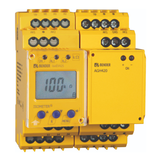
- Page 1 Manual ISOMETER® isoEV425/ isoEV425HC with AGH420 coupling device Insulation monitoring device for unearthed DC circuits (IT systems) for the charging of electric vehicles Software version: D0430 V2.xx/D0640 V2.xx (isoEV425) D0586 V2.xx (isoEV425HC) isoEV425_D00126_09_M_XXEN/03.2019...
- Page 2 Bender GmbH & Co. KG Londorfer Str. 65 • 35305 Gruenberg • Germany P.O. Box 1161 • 35301 Gruenberg • Germany Tel.: +49 6401 807-0 Fax: +49 6401 807-259 E-mail: info@bender.de Web: www.bender.de © Bender GmbH & Co. KG All rights reserved.
-
Page 3: Table Of Contents
Table of Contents 1. Important information ..................6 How to use this manual ................. 6 Technical support: Service and support ..........7 1.2.1 First level support ..................... 7 1.2.2 Repair service ..................... 7 1.2.3 Field service ......................8 Training courses ....................9 Delivery conditions .................. - Page 4 Table of Contents 3.2.10 Fault memory ....................22 3.2.11 History memory HiS ..................22 3.2.12 Interface/protocols ..................23 4. Installation, connection and commissioning ........... 24 Installation ....................... 24 Wiring diagram ....................26 Commissioning ....................28 5. Operation of the device ................29 Display elements ...................
- Page 5 Table of Contents 7. Data access using the Modbus RTU protocol ........... 40 Reading out the Modbus register from the ISOMETER® ....40 7.1.1 Master sends a command to the ISOMETER® ........40 7.1.2 ISOMETER® answers the Master ............... 41 Writing to Modbus registers (parameter setting) ......
-
Page 6: Important Information
1. Important information 1.1 How to use this manual This manual is intended for electrically skilled per- sons working in electrical engineering and electro- nics. Always keep this manual within easy reach for future reference. To make it easier for you to understand and revisit certain sections in this man- ual, we have used symbols to identify important instructions and information. -
Page 7: Technical Support: Service And Support
1.2 Technical support: Service and support For commissioning and troubleshooting Bender offers you: 1.2.1 First level support Technical support by phone or e-mail for all Bender products Questions concerning specific customer applications Commissioning ... -
Page 8: Field Service
Fax: +49 6401 807-789 E-Mail: repair@bender-service.com 1.2.3 Field service On-site service for all Bender products Commissioning, parameter setting, maintenance, troubleshooting for Bender products Analysis of the electrical installation in the building (power quality test, EMC test, thermography) Training courses for customers ... -
Page 9: Training Courses
ZVEI (Zentralverband Elektrotechnik- und Elektronikindus- trie e.V.) (German Electrical and Electronic Manufacturers' Association) also applies. Sale and delivery conditions can be obtained from Bender in printed or elec- tronic format. 1.5 Inspection, transport and storage Inspect the dispatch and equipment packaging for damage, and compare the contents of the package with the delivery documents. -
Page 10: Warranty And Liability
Important information 1.6 Warranty and liability Warranty and liability claims in the event of injury to persons or damage to property are excluded if they can be attributed to one or more of the follow- ing causes: Improper use of the device. ... -
Page 11: Disposal
13th August 2005 must be taken back by the manufacturer and disposed of prop- erly. For more information on the disposal of Bender devices, refer to our homepage at www.bender.de -> Service & support. isoEV425_D00126_09_M_XXEN/03.2019... -
Page 12: Safety Instructions
2. Safety instructions 2.1 General safety instructions Part of the device documentation in addition to this manual is the enclosed "Safety instructions for Bender products". 2.2 Work activities on electrical installations Only skilled persons are permitted to carry out the work ne- cessary to install, commission and run a device or system. -
Page 13: Intended Use
Safety instructions 2.3 Intended use The ISOMETER® of the isoEV425 or isoEV425HC series monitors the insulation resistance R of unearthed AC/DC main circuits (IT systems) with nominal sys- tem voltages of 3(N)AC, AC/DC 0 … 690 V or DC 0 …1,000 V. The main appli- cation areas are unearthed DC charging stations (mode 4 acc. -
Page 14: Function
RS-485 (galvanically isolated) including the following protocols: – BMS interface (Bender measuring device interface) for data exchange with other Bender components – Modbus RTU – IsoData (for continuous data output) Password protection to prevent unauthorised parameter changes ... -
Page 15: Functional Description
Function 3.2 Functional description The ISOMETER® measures the insulation resistance R and the system leakage capacitance C between the system to be monitored (L1/+, L2/-) and earth (PE). The RMS value of the nominal system voltage U between L1/+ and L2/- as well as the residual voltages U (between L1/+ and earth) and U (be-... -
Page 16: Monitoring The Insulation Resistance
Function If the values R or U do not violate their release value (response value plus hysteresis) for the period t without interruption, the alarm relays will switch back to their initial position and the alarm LEDs "AL1"/"AL2" stop lighting. If the fault memory is activated, the alarm relays remain in alarm condition and the LEDs light until the reset button "R"... -
Page 17: Self Test/Error Codes
Function 3.2.3 Self test/error codes The integrated self test function checks the function of the insulation moni- toring device, and connection monitoring checks the connections to the sys- tem to be monitored. The alarm relays are not switched during the self test. This can be changed using the parameter "test"... - Page 18 Function The maximum permissible system leakage capacitance is exceeded Action: E.07 Device not suitable for the existing system leakage capaci- tance: uninstall device. Calibration error during device test Action: E.08 If the error continues to exist after checking the device con- nections, there is an error inside the device.
-
Page 19: Malfunction
LEDs "ON"/"AL1"/ "AL2" will flash. If the error occurs again after restarting the device or after a reset to factory settings, then contact Bender Service. 3.2.5 Signalling assignment of the alarm relays K1/K2 The messages "device error", "insulation fault", "insulation impedance fault",... -
Page 20: Measuring And Response Times
Function sages "-R1" and "-R2" indicate an insulation fault assigned to conductor L2/-. If an assignment is not possible, for example in the event of a symmetrical insu- lation fault, the messages corresponding to "+" and "-" are shown together. The message "test"... - Page 21 Function Operating time The operating time t is the time required by the ISOMETER® to determine the measured value. The insulation resistance measured value depends on the insulation resistance R and the system leakage capacitance C . High sys- tem leakage capacitances and system interferences lead to longer operating times.
-
Page 22: Password Protection (On, Off)
Function 3.2.7 Password protection (on, OFF) If password protection has been activated (on), settings can only be made subject to the correct password being entered (0...999). 3.2.8 Factory setting FAC Activating the factory settings will reset all modified settings - with the excep- tion of the interface parameters - to the default values used when the device was delivered. -
Page 23: Interface/Protocols
3.2.12 Interface/protocols The ISOMETER® uses the serial hardware interface RS-485 with the following protocols: The BMS protocol is an essential component of the Bender measuring device interface (BMS bus protocol). Data is transferred using ASCII characters. Modbus RTU ... -
Page 24: Installation, Connection And Commissioning
4. Installation, connection and commissioning Risk of electric shock! Touching uninsulated live conductors can result in death or serious injury. Therefore avoid any physical contact with DANGER active conductors and ensure compliance with the regulations for working on electrical installations. 4.1 Installation DIN rail mounting: ... - Page 25 Installation, connection and commissioning The dimension diagram and sketches outlining how the device can be screw- mounted and DIN rail mounting are shown below. Click! Click & All dimensions in mm The front plate cover can be opened at the lower part marked with an arrow. isoEV425_D00126_09_M_XXEN/03.2019...
-
Page 26: Wiring Diagram
Installation, connection and commissioning 4.2 Wiring diagram L1/+ L2/- Test / Reset GND AK1 A1 A2 AK1 GND AK2 AK2 GND isoEV425 AGH420 < ISOMETER MENU L2/- L1/+ COM465 IP L1/+ RS-485 Danger from touching hot surfaces! If the AGH420 is operated at mains voltages > 800 V, the temperature of the enclosure may exceed 60 °C. - Page 27 Installation, connection and commissioning Wiring diagram legend: Terminal Connections Connection to the supply voltage U via a fuse: A1, A2 If supplied from an IT system, both lines have to be protected by a fuse.* Connect each terminal separately to PE: E, E, KE "...
-
Page 28: Commissioning
Installation, connection and commissioning 4.3 Commissioning 1. Check that the ISOMETER® is properly connected to the system to be monitored. 2. Connecting supply voltage U to the ISOMETER® The device carries out a calibration, a self test and adjusts itself to the IT system to be monitored. -
Page 29: Operation Of The Device
5. Operation of the device The menu structure is illustrated schematically on the following pages. After pressing the "MENU" button for > 1.5 s, the first "AL" menu item appears. (Enter) buttons for navigation and settings. Up and down button: - navigate up or down in the menu settings - increase or decrease values Pressing the MENU/Enter button for more than... -
Page 30: Display Elements
Operation of the device 5.1 Display elements Device front/display Function green - on Assignment according to yellow - alarm table on Page 33 yellow - alarm ON AL1 AL2 Up button Test button ( press > 1.5 s) Down button Reset button (press >... -
Page 31: Menu Structure
Operation of the device 5.2 Menu structure Measurement display Standard display Menu selection Menu Enter t > 5 min. R [kΩ] Enter C [μF] U L1 L2 [ V] Parameter selection UL1 [ V] UL2 [ V] R [ %] . -
Page 32: Menu "Al
Operation of the device 5.3 Menu "AL" 5.3.1 Response value setting The two parameters that monitor the insulation resistance, "R1" and "R2", can be found in the response value menu "AL". The value R1 can only be set higher than the value R2. If the insulation resistance R reaches or falls below the ac- tivated values R1 or R2, then this leads to an an alarm message. -
Page 33: Menu "Out
Operation of the device 5.4 Menu "out" 5.4.1 Configuration of the relay operating mode Relay K1 Relay K2 Description Display Display Operating mode of n.c. n.c. the relay n.c./n.o. FAC = Factory setting; Cs = User settings 5.4.2 Relay alarm assignment "r1" and "r2" and LED assignment In the alarm assignment, each alarm is assigned to the respective relay with the setting "on". -
Page 34: Fault Memory Configuration
Operation of the device Alarm K1 "r1" K2 "r2" LEDs description ON AL1 AL2 Display Display Alarm U > V U > V Overvoltage Manually started test test device test Device start with ... -
Page 35: Interface Configuration
Operation of the device 5.4.4 Interface configuration Display Setting value Description Value range FAC Adr = 0 deactivates BMS as well as Modbus and acti- 0 / 3 … 90 vates isoData with continu- adr. ous data output (115k2, 8E1) "---"... -
Page 36: Menu "T
0 . . . 999 parameter setting Test of the system connec- off* tion during device test S.Ct Device test during device start Restore factory settings For Bender Service only FAC = Factory setting; Cs = User settings *applies to isoEV425-D49-4 isoEV425_D00126_09_M_XXEN/03.2019... -
Page 37: Measured Value Display And History Memory
Operation of the device 5.7 Measured value display and history memory All other measured value displays switch to the standard display (insulation resistance) after a maximum of 5 min. The pulse symbol indicates a current measured value. If this symbol does not appear, the measurement is still run- ning and the latest valid measured value will be displayed. - Page 38 Operation of the device Display Description Insulation resistance ± R kΩ 1 kΩ … 1 MΩ Resolution 1 kΩ System leakage capacitance 1 μF … 10 μF (isoEV425) Resolution 1 μF μF 1 μF … 25 μF (isoEV425HC) Nominal system voltage L1 - L2 ...
-
Page 39: Data Access Using The Bms Protocol
6. Data access using the BMS protocol The BMS protocol is an essential component of the Bender measuring device interface (BMS bus protocol). ASCII characters are used for the data transfer. BMS channel Operation value Alarm Pre-alarm R1 Alarm R2... -
Page 40: Data Access Using The Modbus Rtu Protocol
7. Data access using the Modbus RTU protocol Requests to the ISOMETER® can be made using the function code 0x03 (read multiple registers) or the command 0x10 (write multiple registers). The ISO- METER® generates a function-related answer and sends it back. 7.1 Reading out the Modbus register from the ISOMETER®... -
Page 41: Isometer® Answers The Master
Data access using the Modbus RTU protocol 7.1.2 ISOMETER® answers the Master Byte Name Example Byte 0 ISOMETER® Modbus address 0x03 Byte 1 Function code 0x03 Byte 2 Number of data bytes 0x02 Byte 3, 4 Data 0x0047 Byte 7, 8 CRC16 Checksum 0x81B6 7.2 Writing to Modbus registers (parameter setting) -
Page 42: Isometer® Answers The Master
Data access using the Modbus RTU protocol 7.2.2 ISOMETER® answers the Master Byte Name Example Byte 0 ISOMETER® Modbus address 0x03 Byte 1 Function code 0x10 Byte 2, 3 Start register 0x0BBB Byte 4, 5 Number of registers 0x0001 Byte 6, 7 CRC16 Checksum 0x722A 7.3 Exception code... -
Page 43: Modbus Register Assignment Of The Isometer
8. Modbus register assignment of the ISOMETER® Depending on the device condition, the information in the registers is: the measured value without alarm, the measured value with alarm 1, the measured value with alarm 2 or only the device fault. Measured value Register Device fault... - Page 44 Modbus register assignment of the ISOMETER® Measured value Register Device fault Without Alarm 1 Alarm 2 alarm 1016 Voltage (76) [no alarm] 1019 1020 Voltage (76) [no alarm] 1023 Fault location 1024 in % --- (1022) 1027 [no alarm] 1028 Insulation fault (71) 1031...
- Page 45 Modbus register assignment of the ISOMETER® Unit Property Description Format Value range Register Number of Mod- UINT 16 0…3 measured value channels with active alarm 3000 Reserved 3001 Reserved 3002 Reserved 3003 Reserved 3004 Reserved Pre-alarm value 3005 resistance meas- UINT 16 kΩ...
- Page 46 Modbus register assignment of the ISOMETER® Unit Property Description Format Value range Register Memory function for alarm mes- 0 = Inactive 3012 sages UINT 16 1 = Active (Fault memory) "M" Operating mode 0 = n.o. 3013 UINT 16 of relay 1 "r1" 1 = n.c.
- Page 47 Modbus register assignment of the ISOMETER® Unit Property Description Format Value range Register Delay on release 3020 "toff" for relays K1 UINT 16 0 … 99 and K2 Repetition time 0 = OFF "test" for auto- 3021 UINT 16 1 = 1 h matic 2 = 24 h device test...
- Page 48 Modbus register assignment of the ISOMETER® Unit Property Description Format Value range Register Factory setting only for 8004 parameters reset- UINT 16 0x4653 "FS" table by FAC Start device test 8005 UINT 16 0x5445 "TE" Clear fault mem- 8006 UINT 16 0x434C "CL"...
-
Page 49: Isometer® Device-Specific Data Type
Modbus register assignment of the ISOMETER® 8.1 ISOMETER® device-specific data type 8.1.1 Device name The data format of the device name is specified below. Word 0x01 0x02 0x03 ------------------- 0x08 0x09 0x00 10 Words in total Each Word contains two ASCII characters 8.1.2 Measured values Each measured value is available as a channel and consists of 8 bytes (4 regis-... -
Page 50: Float = Floating Point Value Of The Channels
Modbus register assignment of the ISOMETER® 8.1.2.1 Float = Floating point value of the channels 0x00 0x01 HiByte LoByte HiByte LoByte S E E E E E E E E M M M M M M M M M M M M M M M M M M M M M M M Presentation of the bit order for processing analogue measured values ac- cording to IEEE 754 S = Sign;... -
Page 51: At&T = Alarm Type And Test Type (Internal/External)
Modbus register assignment of the ISOMETER® 8.1.2.2 AT&T = Alarm type and test type (internal/external) Description No alarm Pre-warning Device error Reserved Warning Alarm Reserved … … … Reserved Reserved No test Internal test External test The alarm type is coded by the bits 0 to 2. Bits 3, 4 and 5 are reserved and al- ways have the value 0. -
Page 52: R&U = Range And Unit
Modbus register assignment of the ISOMETER® 8.1.2.3 R&U = Range and unit Description Invalid (init) No unit Ω Baud °C °F Second Minute Hour Month Actual value The actual value is lower The actual value is higher Invalid value The units of bits 0 to 4 are coded. ... -
Page 53: Alarm Assignment Of The Relays
Modbus register assignment of the ISOMETER® 8.1.3 Alarm assignment of the relays Several alarms can be assigned to each relay. For the assignment of each relay, a 16-bit register is used with the bits described below. The following table ap- plies to relay 1 and relay 2, in which "x"... -
Page 54: Channel Descriptions
Modbus register assignment of the ISOMETER® Display indication Description When reading, always 0 Reserved When writing, any value When reading, always 0 Reserved When writing, any value When reading, always 0 Reserved When writing, any value 8.2 Channel descriptions Measured value description/alarm Value Note... - Page 55 Modbus register assignment of the ISOMETER® To convert parameter data, data type descriptions are required. Text repre- sentation is not necessary in this case. Value Description of parameters 1023 (0x3FF) Parameter/measured value invalid. The menu item of this parameter is not displayed. 1022 (0x3FE) No measured value/no message 1021 (0x3FD) Measured value/parameter inactive 1020 (0x3FC) Measured value/parameter only temporarily inactive (e.g.
-
Page 56: Isodata Data String
9. IsoData data string In IsoData mode, the ISOMETER® continuosly sends the whole data string with a cycle time of approximately 1 s. Communication with the ISOMETER® within this mode is not possible and no additional sender may be connected via the RS-485 bus cable. - Page 57 IsoData data string String Description Alarm message [hexadecimal] (without leading "0x") The alarms are included in this value with the OR function. Assignment of the alarms: 0x0002 Device fault 0x0004 Prewarning insulation resistance R at L1/+ 0x0008 Prewarning insulation resistance R at L2/- 1234;...
-
Page 58: Technical Data
10. Technical data 10.1 Tabular presentation ( )* = Factory setting Insulation coordination acc. to IEC 60664-1/IEC 60664-3 Definitions: Supply circuit (IC2) ............................A1, A2 Output circuit (IC3)........................... 11, 14, 24 Control circuit (IC4) .................... Up, KE, T/R, A, B, AK1, GND, AK2 Rated voltage................................ - Page 59 Technical data IT system being monitored Nominal system voltage with AGH420 ............ 3(N)AC, AC 0…690 V/DC 0…1,000 V Tolerance of ........................... AC +15 %, DC +10 % Nominal system voltage range with AGH420 (UL508) ..............AC/DC 0…600 V Frequency range of ..........................DC, 15…460 Hz Measuring circuit Permissible system leakage capacitance...
- Page 60 Technical data Display range measured value nominal system voltage ( ) ............30…1.15 kV Operating uncertainty........................± 5 %, at least ± 5 V Display range measured value system leakage capacitance > 10 kΩ (isoEV425) ........0…10 μF Display range measured value system leakage capacitance >...
- Page 61 Technical data Classification of mechanical conditions acc. to IEC 60721 Stationary use (IEC 60721-3-3) ..........................3M4 Transport (IEC 60721-3-2) ............................. 2M4 Long-term storage (IEC 60721-3-1) ........................1M12 Connection Connection type..................screw-type terminal or push-wire terminal Screw-type terminals: Nominal current..............................≤ 10 A Tightening torque.......................0.5…0.6 Nm (5…7 lb-in) Conductor sizes.............................
- Page 62 Technical data Other Operating mode ........................... continuous operation Mounting...................... cooling slots must be ventilated vertically Degree of protection, built-in components (DIN EN 60529) ................. IP30 Degree of protection, terminals (DIN EN 60529) ....................IP20 Enclosure material ............................polycarbonate DIN rail mounting acc. to..........................IEC 60715 Screw fixing .........................
- Page 63 Technical data Measuring circuit Measuring voltage ............................± 45 V Measuring current ..........................≤ 400 μA ..........................≥ 120 kΩ Internal resistance DC Environment / EMC EMC ................................. IEC 61326-2-4 Ambient temperatures: Operation ..............................-40…+70 °C Transport ..............................-40…+85 °C Storage ..............................-40…+70 °C Classification of climatic conditions acc.
- Page 64 Technical data Stripping length ..............................10 mm Rigid.................................0.2…2.5 mm Flexible without ferrules ........................0.75…2.5 mm Flexible with ferrules with plastic sleeve .....................0.25…2.5 mm Multi-conductor flexible with TWIN ferrules with plastic sleeve............0.5…1.5 mm Opening force ................................50 N Test opening, diameter ............................2.1 mm Connection type .........................terminals Up, AK1, GND, AK2 Single cables for terminals Up, AK1, GND, AK2: Cable lengths..............................
-
Page 65: Standards, Approvals And Certifications
Technical data 10.2 Standards, approvals and certifications The ISOMETER® has been developed in compliance with the following standards: DIN EN 61557-8 (VDE 0413-8): 2015-12/Ber1: 2016-12 IEC 61557-8 -8: 2014/COR1: 2016 Subject to change! The specified standards take into account the edition valid until 02.2019 unless otherwise indicated. -
Page 66: Ordering Data
Technical data 10.3 Ordering data Automatic Type Art. No. self test isoEV425-D4-4 enabled B71036401 with AGH420 isoEV425-D4-4 enabled B91036401 with AGH420 isoEV425HC- enabled B71036397 D4-4 with AGH420 isoEV425-D49- disabled B71036392 4 with AGH420 Mounting clip for screw B98060008 fixing (1 piece per device) isoEV425_D00126_09_M_XXEN/03.2019... - Page 67 Technical data isoEV425_D00126_09_M_XXEN/03.2019...
- Page 68 INDEX AGH420 Factory setting 22 - Technical data 62 Fault memory 22 Functional description 15 Commissioning 28 Configuration 33 History memory 22 - Fault memory 34 How to use this manual 6 - Function 36 - Interface 35 Installation 24 - Relay operating mode 33 Interface/protocols - Time 36...
- Page 69 Modbus - Function code 40 Work activities on electrical installations 12 - Register assignment 43 Monitoring - for undervoltage and overvoltage - the insulation resistance 16 Operating time 21 Operation 29 Ordering information 66 Password protection 22 Reset button T/R 22 Response delay time 21 Response times 20 Response value setting 32...
- Page 72 Bender GmbH & Co. KG Londorfer Str. 65 • 35305 Gruenberg • Germany P.O. Box 1161 • 35301 Gruenberg • Germany Tel.: +49 6401 807-0 Fax: +49 6401 807-259 E-mail: info@bender.de Web: www.bender.de Group Photos: Bender archive and bendersystembau archive.
Need help?
Do you have a question about the ISOMETER isoEV425 and is the answer not in the manual?
Questions and answers