Sign In
Upload
Manuals
Brands
Bender Manuals
Measuring Instruments
ISOMETER isoEV425HC
Bender ISOMETER isoEV425HC Manuals
Manuals and User Guides for Bender ISOMETER isoEV425HC. We have
1
Bender ISOMETER isoEV425HC manual available for free PDF download: Manual
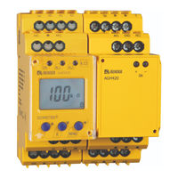
Bender ISOMETER isoEV425HC Manual (72 pages)
Insulation monitoring device for unearthed DC circuits (IT systems) for the charging of electric vehicles
Brand:
Bender
| Category:
Measuring Instruments
| Size: 1 MB
Table of Contents
Table of Contents
3
1 Important Information
6
How to Use this Manual
6
Technical Support: Service and Support
7
First Level Support
7
Repair Service
7
Field Service
8
Training Courses
9
Delivery Conditions
9
Inspection, Transport and Storage
9
Warranty and Liability
10
Disposal
11
2 Safety Instructions
12
General Safety Instructions
12
Work Activities on Electrical Installations
12
Intended Use
13
3 Function
14
Device Characteristics
14
Functional Description
15
Monitoring the Insulation Resistance
16
Undervoltage/Overvoltage Monitoring
16
Self Test/Error Codes
17
Malfunction
19
Signalling Assignment of the Alarm Relays K1/K2
19
Measuring and Response Times
20
Password Protection (On, OFF)
22
Factory Setting FAC
22
External, Combined Test or Reset Button T/R
22
Fault Memory
22
History Memory His
22
Interface/Protocols
23
4 Installation, Connection and Commissioning
24
Installation
24
Wiring Diagram
26
Commissioning
28
5 Operation of the Device
29
Display Elements
30
Menu Structure
31
Menu "AL
32
Response Value Setting
32
Menu "Out
33
Configuration of the Relay Operating Mode
33
Relay Alarm Assignment "R1" and "R2" and LED Assignment
33
Fault Memory Configuration
34
Interface Configuration
35
Menu "T
36
Time Configuration
36
Menu "Set
36
Function Configuration
36
Measured Value Display and History Memory
37
6 Data Access Using the BMS Protocol
39
7 Data Access Using the Modbus RTU Protocol
40
Reading out the Modbus Register from the ISOMETER
40
Master Sends a Command to the ISOMETER
40
ISOMETER® Answers the Master
41
Writing to Modbus Registers (Parameter Setting)
41
Master Sends a Command to the ISOMETER
41
ISOMETER® Answers the Master
42
Exception Code
42
Structure of the Exception Code
42
8 Modbus Register Assignment of the ISOMETER
43
ISOMETER® Device-Specific Data Type
49
Device Name
49
Measured Values
49
Float = Floating Point Value of the Channels
50
AT&T = Alarm Type and Test Type (Internal/External)
51
R&U = Range and Unit
52
Alarm Assignment of the Relays
53
Channel Descriptions
54
9 Isodata Data String
56
10 Technical Data
58
Tabular Presentation
58
Standards, Approvals and Certifications
65
Ordering Data
66
Advertisement
Advertisement
Related Products
Bender ISOMETER isoEV425
Bender ISOMETER isoES425
Bender ISOMETER isoHV525
Bender ISOMETER isoUG425
Bender ISOMETER iso1685FR
Bender iso1685 Series
Bender ISOMETER isoHR685W Series
Bender ISOMETER isoNAV685-D-B
Bender ISOMETER isoHV1685D-425
Bender ISOMETER iso1685D Series
Bender Categories
Measuring Instruments
Monitor
Control Unit
Control Panel
Relays
More Bender Manuals
Login
Sign In
OR
Sign in with Facebook
Sign in with Google
Upload manual
Upload from disk
Upload from URL