Bender ISOMETER isoPV425 Manual
Insulation monitoring device for unearthed dc circuits (it systems) for photovoltaic systems up to 3(n)ac, ac 690 v / dc 1000 v
Hide thumbs
Also See for ISOMETER isoPV425:
- Manual (60 pages) ,
- Quick star manual (9 pages) ,
- Manual (33 pages)
Table of Contents
Advertisement
Quick Links
Advertisement
Table of Contents

Subscribe to Our Youtube Channel
Related Manuals for Bender ISOMETER isoPV425


Summary of Contents for Bender ISOMETER isoPV425
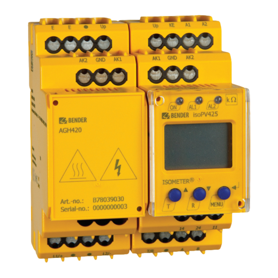
- Page 1 Manual ISOMETER® isoPV425 with AGH420 coupling device Insulation monitoring device for unearthed DC circuits (IT systems) for photovoltaic systems up to 3(N)AC, AC 690 V / DC 1000 V Software version: D404 V2.xx isoPV425_D00028_09_M_XXEN/05.2018...
- Page 2 Bender GmbH & Co. KG Londorfer Str. 65 • 35305 Gruenberg • Germany P.O. Box 1161 • 35301 Gruenberg • Germany Tel.: +49 6401 807-0 Fax: +49 6401 807-259 E-mail: info@bender.de Web: http://www.bender.de © Bender GmbH & Co. KG All rights reserved.
-
Page 3: Table Of Contents
Table of Contents 1. Important information ..................6 How to use this manual ................. 6 Technical support: Service and support ..........7 1.2.1 First level support ..................... 7 1.2.2 Repair service ..................... 7 1.2.3 Field service ......................8 Training courses ....................9 Delivery conditions .................. - Page 4 Table of Contents 3.2.10 Fault memory ....................23 3.2.11 History memory HiS ..................23 3.2.12 Interface/protocols ..................23 4. Installation, connection and commissioning ........... 25 Installation ....................... 25 Wiring diagram ....................27 Commissioning ....................30 5. Operation of the device ................31 Display elements in use ................
- Page 5 Table of Contents 7. Data access using the Modbus RTU protocol ........... 41 Reading out the Modbus register from the ISOMETER® ....41 7.1.1 Master sends a command to the ISOMETER® ........41 7.1.2 ISOMETER® answers the master ............... 42 Writing to Modbus registers (parameter setting) ......
-
Page 6: Important Information
1. Important information 1.1 How to use this manual This manual is intended for electrically skilles persons working in electrical engineering and electronics. Always keep this manual within easy reach for future reference. To make it easier for you to understand and revisit certain sections in this man- ual, we have used symbols to identify important instructions and information. -
Page 7: Technical Support: Service And Support
1.2 Technical support: Service and support For commissioning and troubleshooting Bender offers you: 1.2.1 First level support Technical support by phone or e-mail for all Bender products Questions concerning specific customer applications Commissioning ... -
Page 8: Field Service
Fax: +49 6401 807-789 E-mail: repair@bender-service.com 1.2.3 Field service On-site service for all Bender products Commissioning, parameter setting, maintenance, troubleshooting for Bender products Analysis of the electrical installation in the building (power quality test, EMC test, thermography) Training courses for customers ... -
Page 9: Training Courses
ZVEI (Zentralverband Elektrotechnik- und Elektronikindus- trie e.V.) (German Electrical and Electronic Manufacturers' Association) also applies. Sale and delivery conditions can be obtained from Bender in printed or elec- tronic format. 1.5 Inspection, transport and storage Inspect the dispatch and equipment packaging for damage, and compare the contents of the package with the delivery documents. -
Page 10: Warranty And Liability
Important information 1.6 Warranty and liability Warranty and liability claims in the event of injury to persons or damage to property are excluded if they can be attributed to one or more of the follow- ing causes: Improper use of the device. ... -
Page 11: Disposal
13th August 2005 must be taken back by the manufacturer and dis- posed of properly. For more information on the disposal of Bender devices, refer to our homepage at www.bender.de -> Service & support. isoPV425_D00028_09_M_XXEN/05.2018... -
Page 12: Safety Instructions
2. Safety instructions 2.1 General safety instructions Part of the device documentation in addition to this manual is the enclosed "Safety instructions for Bender products". 2.2 Work activities on electrical installations Only skilled persons are permitted to carry out the work necessary to install, commission and run a device or system. -
Page 13: Intended Use
Safety instructions 2.3 Intended use The ISOMETER® of the isoPV425 series monitors the insulation resistance R unearthed AC/DC main circuits (IT systems) with nominal system voltages of 3(N)AC, AC/DC 0 … 690 V or DC 0 …1000 V. DC components existing in 3(N)AC, AC/DC systems do not influence the operating characteristics, when a minimum load current of DC 10 mA flows. -
Page 14: Function
RS-485 (galvanically isolated) including the following protocols: – BMS interface (Bender measuring device interface) for data exchange with other Bender components – Modbus RTU – IsoData (for continuous data output) Password protection to prevent unauthorised parameter changes ... -
Page 15: Functional Description
Function 3.2 Functional description The ISOMETER® measures the insulation resistance R and the system leakage between the system to be monitored (L1/+, L2/-) and earth capacitance C (PE). The RMS value of the nominal system voltage U between L1/+ and L2/- as well as the residual voltages U (between L1/+ and earth) and U (between L2/- and earth) are also measured. -
Page 16: Monitoring The Insulation Resistance
Function switch back to their initial position and the alarm LEDs "AL1"/"AL2" stop lighting. If the fault memory is activated, the alarm relays remain in the alarm condition and the LEDs light until the reset button "R" is pressed or the supply voltage is interrupted. -
Page 17: Undervoltage/Overvoltage Monitoring
Function 3.2.2 Undervoltage/overvoltage monitoring In the response value menu "AL" (see Chapter 5.3), the parameters ("U <" and can be activated or de- "U >") for monitoring the nominal system voltage U activated. The maximum undervoltage value is limited by the overvoltage value. - Page 18 Function Error codes If, contrary to expectations, a device error should occur, error codes will ap- pear on the display. Some of these are described below: Error code Description PE connection error The connections "E" or "KE" to earth are interrupted. E.01 Action: Check connection, eliminate error.
- Page 19 Function Internal device errors "E.xx" can be caused by external disturbances or inter- nal hardware errors. If the error message occurs again after restarting the device or after a reset to factory settings (menu item "FAC") , the device must be repaired.
-
Page 20: Malfunction
LEDs "ON"/"AL1"/ "AL2" will flash. If the error occurs again after restarting the device or after a reset to factory settings, then contact Bender Service. 3.2.5 Signalling assignment of the alarm relays K1/K2 The messages "device error", "insulation fault", "insulation impedance fault",... -
Page 21: Measuring And Response Times
Function 3.2.6 Measuring and response times The measuring time is the period essential for the detection of the measuring value. The measuring time is reflected in the operating time t The measuring time for the insulation resistance value is mainly determined by the required measuring pulse duration, which depends on the insulation resistance R and system leakage capacitance C... -
Page 22: Password Protection (On, Off)
Function Delay on release The delay on release t can be set uniformly for all messages in the menu "t" using the parameter "toff". An alarm will continuously be signalled until the threshold value of the re- spective measuring value is not exceeded (including hysteresis) for the period of t without interruption. -
Page 23: Fault Memory
3.2.12 Interface/protocols The ISOMETER® uses the serial hardware interface RS-485 with the following protocols: The BMS protocol is an essential component of the Bender measuring device interface (BMS bus protocol). Data is transferred using ASCII characters. Modbus RTU ... - Page 24 Function IsoData The ISOMETER® continously sends an ASCII data string with a cycle of approximately 1 second. Communication with the ISOMETER® within this mode is not possible and no additional transmitter may be connect- ed to the RS-485 bus cable. The ASCII data string for the ISOMETER® is described in Chapter 9.
-
Page 25: Installation, Connection And Commissioning
4. Installation, connection and commissioning Risk of electric shock! Touching uninsulated live conductors can result in death or serious injury. Therefore avoid any physical contact with DANGER active conductors and ensure compliance with the regulations for working on electrical installations. 4.1 Installation DIN rail mounting: ... - Page 26 Installation, connection and commissioning Zubehör Klick All dimensions in mm The front plate cover can be opened at the lower part marked with an arrow. isoPV425_D00028_09_M_XXEN/05.2018...
-
Page 27: Wiring Diagram
Installation, connection and commissioning 4.2 Wiring diagram Connect the terminals "A1" and "A2" to the supply voltage U according to IEC 60364-4-43, i.e. the connections are to be protected against a short-circuit by means of a protective device (a 6 A fuse is recommended). Devices for protection against a short circuit in conformity with IEC 60364-4-43 for the coupling of terminals "L1/+"/"L2/-"... - Page 28 Installation, connection and commissioning Connect the device as illustrated in the wiring diagram below: L1/+ L2/- Test / Reset GND AK1 A1 A2 AK1 GND AK2 AK2 GND isoPV425 AGH420 < ISOMETER MENU L2/- L1/+ COM465IP L1/+ RS-485 Danger from touching hot surfaces! If the AGH420 is operated at mains voltages >...
- Page 29 Installation, connection and commissioning For details about the conductor cross sections required for wiring, refer to the technical data on Page Wiring diagram legend: Terminal Connections Connection to the supply voltage U via a fuse: If supplied from an IT system, both lines have to be protected by a A1, A2 fuse.* Connect each terminal separately to PE:...
-
Page 30: Commissioning
Installation, connection and commissioning 4.3 Commissioning 1. Check that the ISOMETER® is properly connected to the system to be monitored. 2. Connecting supply voltage U to the ISOMETER® The device carries out a calibration, a self test and adjusts itself to the IT system to be monitored. -
Page 31: Operation Of The Device
5. Operation of the device The menu structure is illustrated schematically on the following pages. After pressing the "MENU" button for > 1.5 s, the first menu "AL" menu item appears. Use (Enter) buttons for navigation and settings. Up and down button: - navigate up or down in the menu settings - increase or decrease values Pressing the MENU/Enter button for more than... -
Page 32: Display Elements In Use
Operation of the device 5.1 Display elements in use Device front/display Function green - on Assignment according to yellow - alarm table on Page 35 yellow - alarm AL1 AL2 Up button Test button ( press > 1.5 s) Down button Reset button (press >... -
Page 33: Menu Structure
Operation of the device 5.2 Menu structure Measurement display Standard display Menu selection Menu Enter t > 5 min. R [kΩ] Enter C [µF] U L1 L2 [ V] Parameter selection UL1 [ V] UL2 [ V] R [ %] . -
Page 34: Menu "Al
Operation of the device 5.3 Menu "AL" 5.3.1 Response value setting The two parameters that monitor the insulation resistance, "R1" and "R2", can be found in the response value menu "AL". The value R1 can only be set higher than the value R2. If the insulation resistance R reaches or falls below the ac- tivated values R1 or R2, then this leads to an alarm message. -
Page 35: Menu "Out
Operation of the device 5.4 Menu "out" 5.4.1 Configuration of the relay operating mode Relay K1 Relay K2 Description Display Display Operating mode of n.c. n.c. the relay n.c./n.o. FAC = Factory setting; Cs = User settings 5.4.2 Relay alarm assignment "r1" and "r2" and LED assignment In the alarm assignment, each alarm is assigned to the respective relay with the setting "on". -
Page 36: Fault Memory Configuration
Operation of the device Alarm K1 "r1" K2 "r2" LEDs description ON AL1 AL2 Display Display Alarm U > V U > V Overvoltage Manually started test test device test Device start with ... -
Page 37: Interface Configuration
Operation of the device 5.4.4 Interface configuration Display Setting value Description Value range FAC Adr = 0 deactivates BMS as well as Modbus and acti- 0 / 3 … 90 vates isoData with continu- adr. ous data output (115k2, 8E1) “---“... -
Page 38: Menu "Set
S.Ct Device test during device start Restore factory settings For Bender Service only FAC = Factory setting; Cs = User settings 5.7 Measuring value display and history memory All other measuring value displays switch to the standard display (insulation resistance) after a maximum of 5 min. The pulse symbol indicates the current measured value. - Page 39 Operation of the device Display Description Nominal system voltage L1 - L2 ~ ± U L1 L2 … 1.20 kV Resolution 1 V / 10 V Residual voltage L1/+ - PE ± U L1 … ±1.20 kV Resolution 1 V / 10 V Residual voltage L2/- - PE ...
-
Page 40: Data Access Using The Bms Protocol
6. Data access using the BMS protocol The BMS protocol is an essential component of the Bender measuring device interface (BMS bus protocol). ASCII characters are used for the data transfer. BMS channel Operation value Alarm Pre-alarm R1 Alarm R2... -
Page 41: Data Access Using The Modbus Rtu Protocol
7. Data access using the Modbus RTU protocol Requests to the ISOMETER® can be made using the function code 0x03 (read multiple registers) or the command 0x10 (write multiple registers). The ISO- METER® generates a function-related answer and sends it back. 7.1 Reading out the Modbus register from the ISOMETER®... -
Page 42: Isometer® Answers The Master
Data access using the Modbus RTU protocol 7.1.2 ISOMETER® answers the master Byte Name Example Byte 0 ISOMETER® Modbus address 0x03 Byte 1 Function code 0x03 Byte 2 Number of data bytes 0x02 Byte 3, 4 Data 0x0047 Byte 7, 8 CRC16 Checksum 0x81B6 7.2 Writing to Modbus registers (parameter setting) -
Page 43: Isometer® Answer To The Master
Data access using the Modbus RTU protocol 7.2.2 ISOMETER® answer to the master Byte Name Example Byte 0 ISOMETER® Modbus address 0x03 Byte 1 Function code 0x10 Byte 2, 3 Start register 0x0BBB Byte 4, 5 Number of registers 0x0001 Byte 6, 7 CRC16 Checksum 0x722A... -
Page 44: Modbus Register Assignment Of The Isometer
8. Modbus register assignment of the ISOMETER® Depending on the device status, the information in the registers is either: the measured value without alarm; the measured value with alarm 1; the meas- ured value with alarm 2; or only the device fault. Measured value Register Device fault... - Page 45 Modbus register assignment of the ISOMETER® Measured value Register Device fault Without alarm Alarm 1 Alarm 2 1020 Voltage (76) [no alarm] 1023 Fault location 1024 in % --- (1022) 1027 [no alarm] 1028 Insulation fault (71) 1031 [no alarm] Measured value 1032 update counter...
- Page 46 Modbus register assignment of the ISOMETER® Unit Property Description Format Value range Register Pre-alarm value 3005 resistance meas- UINT 16 kΩ R2 … 500 urement "R1" 3006 Reserved Alarm value resist- 3007 ance measure- UINT 16 kΩ 1 … R1 ment "R2"...
- Page 47 Modbus register assignment of the ISOMETER® Unit Property Description Format Value range Register 0 = BMS 1 = 1.2 k 2 = 2.4 k 3 = 4.8 k 3016 Baud rate "Adr 1" UINT 16 4 = 9.6 k 5 = 19.2 k 6 = 38.4 k 7 = 57.6 k 8 = 115.2 k...
- Page 48 Modbus register assignment of the ISOMETER® Unit Property Description Format Value range Register 3025 Device test during UINT 16 0 = Inactive device start "S. Ct" 1 = Active Request stop mode (0 = deacti- 0 = Stop 3026 UINT 16 vate device) 1 = --- Alarm assignment...
-
Page 49: Isometer® Device-Specific Data Type
Modbus register assignment of the ISOMETER® Unit Property Description Format Value range Register Software version: 9822 UINT 16 year Software version: 9823 UINT 16 Month Software version: 9824 UINT 16 Modbus driver ver- 9825 UINT 16 sion RW = Read/Write; RO = Read Only;... -
Page 50: Measuring Values
Modbus register assignment of the ISOMETER® 8.1.2 Measuring values Each measuring value is available as a channel and consists of 8 bytes (4 reg- isters). The first measuring value register address is 1000. The structure of a channel is always identical. Content and number depend on the device. The structure of a channel is shown with the example of channel 1: 1000 1001... -
Page 51: At&T = Alarm Type And Test Type (Internal/External)
Modbus register assignment of the ISOMETER® 8.1.2.2 AT&T = Alarm type and test type (internal/external) Description No alarm Prewarning Device error Reserved Warning Alarm Reserved … … … Reserved Reserved No test Internal test External test The alarm type is coded by bits 0 to 2. Bits 3, 4 and 5 are reserved and always have the value 0. -
Page 52: R&U = Range And Unit
Modbus register assignment of the ISOMETER® 8.1.2.3 R&U = Range and unit Description Invalid (init) No unit Ω Baud °C °F Second Minute Hour Month Actual value The actual value is lower The actual value is higher Invalid value The units of bits 0 to 4 are coded. ... -
Page 53: Alarm Assignment Of The Relays
Modbus register assignment of the ISOMETER® 8.1.3 Alarm assignment of the relays Several alarms can be assigned to each relay. For the assignment of each relay, a 16-bit register is used with the bits described below. The following table ap- plies to relay 1 and relay 2, in which "x"... -
Page 54: Channel Descriptions
Modbus register assignment of the ISOMETER® Display indication Description When reading, always 0 Reserved When writing, any value When reading, always 0 Reserved When writing, any value When reading, always 0 Reserved When writing, any value 8.2 Channel descriptions Measured value description/alarm Value Note... - Page 55 Modbus register assignment of the ISOMETER® To convert parameter data, data type descriptions are required. Text representation is not necessary in this case. Value Description of parameters 1023 (0x3FF) Parameter/measured value invalid. The menu item of this parameter is not displayed. 1022 (0x3FE) No measured value/no message 1021 (0x3FD) Measured value/parameter inactive 1020 (0x3FC) Measured value/parameter only temporarily inactive (e.g.
-
Page 56: Isodata Data String
9. IsoData data string In IsoData mode, the ISOMETER® continuosly sends the whole data string with a cycle time of approximately 1 second. Communication with the ISOMETER® in this mode is not possible and no additional sender may be connected via the RS-485 bus cable. - Page 57 IsoData data string String Description Alarm message [hexadecimal] (without leading "0x") Using the OR function, the alarms are included in this value. Assignment of the alarms: 0x0002 Device fault 0x0004 Prewarning insulation resistance R on L1/+ 0x0008 Prewarning insulation resistance R on L2/- 1234;...
-
Page 58: Technical Data
10. Technical data 10.1 Tabular presentation ( )* = Factory setting Insulation coordination acc. to IEC 60664-1/IEC 60664-3 Definitions: Supply circuit (IC2) ............................A1, A2 Output circuit (IC3)........................... 11, 14, 24 Control circuit (IC4) ....................E, KE, T/R, A, B, AK1, GND, AK2 Rated voltage.................................. - Page 59 Technical data IT system being monitored Nominal system voltage with AGH420 ............. 3(N)AC, AC 0…690 V/DC 0…1000 V Tolerance of ..........................AC +5 %, DC +0 % Nominal system voltage range with AGH420 (UL508) ..............AC/DC 0…600 V Frequency range of ........................
- Page 60 Technical data Display range measured value system leakage capacitance at > 10 kΩ ........... 0…1000 μF Operating uncertainty........................ ±15 %, at least ±2 μF Password ............................off/0…999 (0, off)* Fault memory alarm messages ........................on/(off)* Interface Interface/protocol ....................RS-485/BMS, Modbus RTU, isoData Baud rate ............BMS (9.6 kBit/s), Modbus RTU (selectable), isoData (115.2 kBits/s) Cable length (9.6 kBits/s) ..........................
- Page 61 Technical data Classification of mechanical conditions acc. to IEC 60721 Stationary use (IEC 60721-3-3) ..........................3M4 Transport (IEC 60721-3-2) ............................. 2M2 Long-term storage (IEC 60721-3-1) ........................1M3 Connection Connection type screw-type terminal or push-wire terminal Screw-type terminals: Nominal current..............................≤10 A Tightening torque.......................0.5…0.6 Nm (5…7 lb-in) Conductor sizes.............................
- Page 62 Technical data Enclosure material ............................polycarbonate DIN rail mounting acc. to..........................IEC 60715 Screw fixing ......................... 2 x M4 with mounting clip Weight.................................≤ 150 g Technical data AGH420 Insulation coordination acc. to IEC 60664-1/IEC 60664-3 Definitions: Measuring circuit (IC1) .......................... L1/+, L2/- Control circuit (IC2)........................
- Page 63 Technical data Storage ..............................-40…+70 °C Classification of climatic conditions acc. to IEC 60721: Stationary use (IEC 60721-3-3) ............3K7 (except condensation and formation of ice) Transport (IEC 60721-3-2)..............2K4 (except condensation and formation of ice) Long-term storage (IEC 60721-3-1) ..........1K5 (except condensation and formation of ice) Classification of mechanical conditions acc.
-
Page 64: Standards, Approvals And Certifications
Technical data Cable lengths..............................≤ 0.5 m Connection properties ..................≥ 0.75 mm Other Operating mode ........................... Continuous operation Mounting ..................... cooling slots must be ventilated vertically > 800 V ............... ≥ 30 mm Distance to adjacent devices from Degree of protection internal components (DIN EN 60529) .................. IP30 Degree of protection terminals (DIN EN 60529) ..................... -
Page 65: Ordering Data
Technical data 10.3 Ordering data Type Version Art. No. isoPV425-D4-4 with AGH420 Push-wire terminal B71036303 isoPV425-D4-4 with AGH420 Screw-type terminal B91036303 Mounting clip for screw fixing B98060008 (1 piece per device) isoPV425_D00028_09_M_XXEN/05.2018... - Page 66 INDEX Functional description 15 AGH420 - Technical data 62 History memory 23 How to use this manual 6 Commissioning 25 Configuration 35 Installation 25 - Fault memory 36 Interface/protocols - Function 38 - BMS 23 - Interface 37 - IsoData 24 - Relay operating mode 35 - Modbus RTU 23 - Time 37...
- Page 67 - Insulation resistance 16 Work activities on electrical installations 12 - Undervoltage and overvoltage 17 Operating time 21 Operation 31 Ordering information 65 Password protection 22 Relay alarm assignment 35 Reset button T/R 22 Response delay time 21 Response times 21 Response value setting 34 Safety instructions 12 Self-test 17...
- Page 68 Bender GmbH & Co. KG Londorfer Str. 65 • 35305 Gruenberg • Germany P.O. Box 1161 • 35301 Gruenberg • Germany Tel.: +49 6401 807-0 Fax: +49 6401 807-259 E-mail: info@bender.de Web: http://www.bender.de Photos: Bender archives.
Need help?
Do you have a question about the ISOMETER isoPV425 and is the answer not in the manual?
Questions and answers