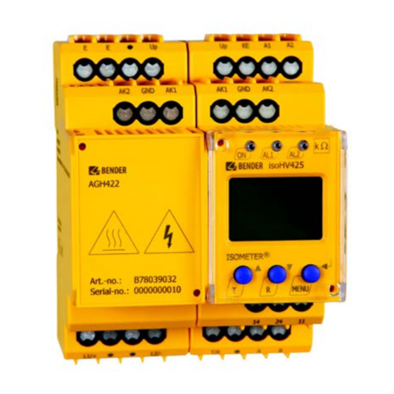
Bender ISOMETER isoHV425 Manual
With agh422 coupling device
Hide thumbs
Also See for ISOMETER isoHV425:
- Manual (49 pages) ,
- Operating manual (33 pages) ,
- Quick start manual (12 pages)
Table of Contents
Advertisement
Quick Links
Advertisement
Table of Contents

Related Manuals for Bender ISOMETER isoHV425


Summary of Contents for Bender ISOMETER isoHV425
- Page 1 ISOMETER® isoHV425 with AGH422 coupling device Insulation monitoring device for unearthed AC, AC/DC and DC systems (IT systems) up to 3(N)AC, AC 1000 V Software version: D0453 V1.xx (isoHV425-D4-4) D0500 V1.xx (isoHV425-D4M-4) isoHV425_D00082_02_M_XXEN/05.2020 Manual...
- Page 2 Bender GmbH & Co. KG Londorfer Str. 65 • 35305 Grünberg • Germany PO Box1161 • 35301 Grünberg • Germany Tel.: +49 6401 807-0 • Fax: +49 6401 807-259 E-mail: info@bender.de • www.bender.de © Bender GmbH & Co. KG All rights reserved.
-
Page 3: Table Of Contents
Table of contents 1. Important information ................6 How to use this manual ................... 6 Technical support: service and support ............ 7 1.2.1 First Level Support .................... 7 1.2.2 Repair Service ..................... 7 1.2.3 Field Service ......................8 Training courses ....................8 Delivery conditions ................... - Page 4 Table of contents 4. Mounting, connection and commissioning ........20 Mounting ......................20 Wiring diagram ....................22 4.2.1 Connection isoHV425-D4-4 ................. 22 4.2.2 Connection isoHV425W-D4M-4 with analogue interface: ....23 Commissioning ....................25 5. Operation ....................26 Display elements ..................... 27 Menu overview ....................28 "AL"...
- Page 5 Table of contents 8. IsoData data string (isoHV425-D4-4) ..........45 9. Technical data ..................46 Tabular presentation ..................46 Standards ......................51 Ordering information ..................51 INDEX ......................52 isoHV425_D00082_03_M_XXEN/05.2020...
-
Page 6: Important Information
1. Important information 1.1 How to use this manual This manual is intended for qualified personnel working in electrical engi- neering and electronics! Always keep this manual within easy reach for future reference. To make it easier for you to understand and revisit certain sections of text and instructions in this manual, we have used symbols to identify important instructions and information. -
Page 7: Technical Support: Service And Support
Repair, calibration, testing and analysis Hardware and software update Delivery of replacement devices for faulty or incorrectly delivered Bender devices Extended warranty for Bender devices with in-house repair service or replace- ment devices at no extra cost... -
Page 8: Field Service
ZVEI (Zentralverband Elektrotechnik- und Elektronikindustrie e.V., (German Elec- trical and Electronic Manufacturers' Association) also applies. Conditions of sale and delivery can be obtained from Bender in printed or electronic for- mat. 1.5 Inspection, transport and storage Check the shipping and device packaging for damage and compare the package con- tents with the shipping documents. -
Page 9: Warranty And Liability
13 August 2005 will be taken back by the manufacturer and disposed of properly. For more information on the disposal of Bender devices, refer to our homepage at www.bender.de/en –> Service & support. -
Page 10: Safety Instructions
2. Safety instructions 2.1 General safety instructions In addition to these operating manual, the "Safety instructions for Bender products", which are also included in the scope of supply, are an integral part of the device docu- mentation. 2.2 Work activities on electrical installations... -
Page 11: Intended Use
Important information 2.3 Intended use Only qualified personnel are permitted to carry out the work necessary to install, commission and run a device or system. The ISOMETER® monitors the insulation resistance R of unearthed AC, AC/DC and DC systems (IT systems) with system voltages of 3(N)AC, AC/DC 0…1000 V or DC 0…1000 V. -
Page 12: Function
Password protection to prevent unauthorised parameter changes isoHV425-D4-4 RS-485 (galvanically separated) including the following protocols: – BMS interface (Bender measuring device interface) for data exchange with other Bender components – Modbus RTU – IsoData (for continuous data output) isoHV425-D4M-4 Analogue output (galvanically separated) ... -
Page 13: Monitoring Of The Insulation Resistance
Important information The partial resistances can be calculated from the total insulation resistance R and the faulty conductor (R %) using the following formula: Fault on conductor L1/+ –>R = (200 % * R )/(100 % + R %) Fault on conductor L2/- –>... -
Page 14: Undervoltage/Overvoltage Monitoring
Important information 3.2.2 Undervoltage/overvoltage monitoring In the response value menu "AL" (see Page 29), the two parameters ("U <" and "U >") for monitoring the system voltage U can be activated or deactivated. The maxi- mum undervoltage value is limited by the overvoltage value. The r.m.s. - Page 15 Important information Error codes If a device error occurs, the following error codes appear on the display: Error code Description PE connection error The connection of terminals E or KE to earth is interrupted. E.01 Action: Check connection, eliminate error. The error code will be erased automatically once the error has been eliminated.
-
Page 16: Signalling Assignment Of The Alarm Relays K1/K2
"E.09" to "E.16" appear. If the error occurs again after restarting the device or after a reset to factory settings, contact Bender Service. Continuous PE connection monitoring The connection of terminal E of the AGH to the PE protective conductor is monitored continuously and in parallel with the measuring function of the device via the input KE of the isoCHA425HV, which is also connected to the PE protective conductor. -
Page 17: Measuring And Response Times
Important information 3.2.5 Measuring and response times The measuring time is the time required to detect a measured value. The measuring time is reflected in the operating time t . The measuring time for the measured insula- tion resistance value is mainly determined by the required measuring pulse duration, which depends on the insulation resistance R and the system leakage capacitance C of the system to be monitored. -
Page 18: Password Protection (On, Off)
Important information 3.2.6 Password protection (on, OFF) If password protection has been activated (on), settings can only be made if the correct password has been entered (0...999). 3.2.7 Factory setting FAC Activating the factory settings will reset all modified settings ? with the exception of the interface parameters ? to the default values upon delivery. -
Page 19: Digital Interfaces (Isohv425-D4-4)
3.2.11 Digital interfaces (isoHV425-D4-4) The ISOMETER® uses the serial hardware interface RS-485 with the following protocols: The BMS protocol is an essential component of the Bender measuring device interface (BMS bus protocol). Data is transferred using ASCII characters. Modbus RTU ... -
Page 20: Mounting, Connection And Commissioning
4. Mounting, connection and commissioning Only qualified personnel are permitted to carry out the work necessary to install, commission and run a device or system. Risk of electrocution due to electric shock! Touching live parts of the system carries the risk of: An electric shock ... - Page 21 Important information Dimension diagram, sketch for screw mounting, push-wire terminal connection: Click! Click & All dimensions in mm The front plate cover can be opened at the lower part marked with an arrow. isoHV425_D00082_03_M_XXEN/05.2020...
-
Page 22: Wiring Diagram
Important information 4.2 Wiring diagram 4.2.1 Connection isoHV425-D4-4 L1/+ L2/- Test / Reset GND AK2 isoHV425 AGH422 ISOMETER® MENU L1/+ L2/- COM465IP L1/+ L2/- RS-485 isoHV425_D00082_03_M_XXEN/05.2020... -
Page 23: Connection Isohv425W-D4M-4 With Analogue Interface
Important information 4.2.2 Connection isoHV425W-D4M-4 with analogue interface: L1/+ L2/- Test / Reset GND AK2 isoHV425 AGH422 ISOMETER® MENU L1/+ L2/- L2/- L1/+ For details about the conductor cross sections required for wiring, refer to the technical data fromPage 46 isoHV425_D00082_03_M_XXEN/05.2020... - Page 24 Important information Legend of the wiring diagrams: Terminal Connections Connection to the supply voltage U via fuse (line protection): If being supplied A1, A2 from an IT system, both lines have to be protected by a fuse. Connect each terminal separately to PE: E, E, KE The same wire cross section as for A1, A2 is to be used.
-
Page 25: Commissioning
Important information 4.3 Commissioning 1. Check that the ISOMETER® is properly connected to the system to be moni- tored. 2. Connect the supply voltage U for ISOMETER®. The device carries out a calibration, a self test and adjusts itself to the IT sys- tem to be monitored. -
Page 26: Operation
5. Operation The menu structure is illustrated schematically on the following pages. If the "MENU" button is pressed for more than 1.5 s, the first menu item "AL" appears. (enter) buttons for navigation and settings. Up and down button: - Navigate up or down in the menu settings - Increase or decrease values Pressing the MENU/enter button for more than 1.5 s: - Start menu mode... -
Page 27: Display Elements
Important information 5.1 Display elements Device front/display Function green - on yellow - alarm yellow - alarm ON AL1 AL2 Up button Test button (press > 1.5 s) By pressing and holding the test button, the display elements are indicated Down button Reset button (press >... -
Page 28: Menu Overview
Important information 5.2 Menu overview Measured value display Menu selection Parameter input > < 1.5 s > > 1.5 s 1.5 s . . . < t > 5 Min. < > 1.5 s R [kΩ] Password (optional) C [μF] U L1 L2 [V ] UL1 [V ] <... -
Page 29: Al" Menu - Response Value Setting
Important information 5.3 "AL" menu – response value setting The two parameters "R1" and "R2" for monitoring the insulation resistance R can be found in the response value menu "AL". The value "R1" can only be set higher than the value "R2". -
Page 30: Relay Signalling Assignment "R1" And "R2" And Led Assignment
Important information 5.4.2 Relay signalling assignment "r1" and "r2" and LED assignment In the signalling assignment, each notification/alarm is assigned to the respective relay with the setting "on". The LED indication is directly assigned to the alarms and is not re- lated to the relays. -
Page 31: Interface Configuration (Isohv425-D4-4)
Important information 5.4.4 Interface configuration (isoHV425-D4-4) Setting value Description Display Value range Adr = 0 deactivates BMS as well as Mod- 0 / 3 … 90 ) BusAdr. bus and activates isoData with continu- ous data output (115k2, 8E1) "–––" ––>... -
Page 32: T" Menu - Time Configuration
0 . . . 999 Password for parameter setting Test of the system connection L1/+, L2/- during device test S.Ct Device test during device start Restore factory settings For Bender Service only FAC = Factory setting; Cs = Customer settings isoHV425_D00082_03_M_XXEN/05.2020... -
Page 33: Measured Value Display And History Memory
Important information 5.7 Measured value display and history memory is continuously indicated on the display (standard display). All other measured value displays switch to the standard display after a maximum of 5 minutes. The pulse symbol indicates a present measured value. If this symbol does not appear, the measurement is still running and the latest valid measured value will be displayed. -
Page 34: Bms Protocol (Isohv425-D4-4)
6. BMS protocol (isoHV425-D4-4) The BMS protocol is a component of the Bender measuring device interface (BMS bus protocol). Data is transferred using ASCII characters. BMS channel no. Operation value Alarm Prewarning R1 Alarm R2 –––– Undervoltage Overvoltage ––– Connection error earth (E.01) –––... -
Page 35: Modbus Rtu Protocol (Isohv425-D4-4)
7. Modbus RTU protocol (isoHV425-D4-4) Requests to the ISOMETER® can be made using the function code 0x03 (read multiple registers) or the command 0x10 (write multiple registers). The ISOMETER® generates a function-related answer and sends it back. 7.1 Reading out the Modbus register from the ISOMETER® The required words of the process image can be read out from the "Holding registers"... -
Page 36: The Master Sends A Command To The Isometer
Important information 7.2.1 The master sends a command to the ISOMETER® In this example, the master addresses the ISOMETER® with address 3 and requests that the content of the register with address 3003 is set to 2. Byte Name Example Byte 0 ISOMETER®... -
Page 37: Modbus Register Assignment
Important information 7.4 Modbus register assignment Depending on the device state, the information in the registers is either the measured value without alarm, the measured value with alarm 1, the measured value with alarm 2 or only the device error. Measured value Register Device error... - Page 38 Register Mode Description Format Unit Value range 3000 Reserved ––– ––– ––– 3001 Reserved ––– ––– ––– 3002 Reserved ––– ––– ––– 3003 Reserved ––– ––– ––– 3004 Reserved ––– ––– ––– Prewarning value 3005 Uint16 kΩ R2 … 500 resistance measurement "R1"...
- Page 39 Important information Register Mode Description Format Unit Value range Delay on release "toff" for relays 3020 Uint16 0 … 99 K1 and K2 0 = OFF Repetition time "test" for auto- 3021 Uint16 ––– 1 = 1 h matic device test 2 = 24 h 3022 Reserved...
-
Page 40: Device-Specific Data Types
Important information 7.5 Device-specific data types 7.5.1 Device name The data format of the device name is specified below. Word 0x01 0x02 0x03 ––––––––––––––––––– 0x08 0x09 0x00 10 words in total Each word contains two ASCII characters 7.5.2 Measured values Each measured value is available as a channel and consists of 8 bytes (4 registers). - Page 41 Important information 7.5.2.2 AT&T = Alarm type and test type (internal/external) Meaning No alarm Prewarning Device error Reserved Warning Alarm Reserved … … … Reserved Reserved No test Internal test External test The alarm type is coded by the bits 0 to 2. Bits 3, 4 and 5 are reserved and always have the value 0.
- Page 42 Important information 7.5.2.3 R&U = Range and unit Meaning – – – Invalid (init) – – – No unit – – – Ω – – – – – – – – – – – – – – – Baud – –...
-
Page 43: Alarm Assignment Of The Relays
Important information 7.5.3 Alarm assignment of the relays Several alarms can be assigned to each relay. For the assignment of each relay, a 16-bit register is used with the bits described below. The following table applies to relay 1 and relay 2, in which "x"... -
Page 44: Channel Descriptions
Important information 7.5.4 Channel descriptions Measured value description/ Value Note alarm and operating message 1 (0x01) Insulation fault 71 (0x47) Insulation resistance R in Ω Insulation fault 76 (0x4C) Voltage Measured value in V 77 (0x4D) Undervoltage 78 (0x4E) Overvoltage 82 (0x52) Capacitance Measured value in F... -
Page 45: Isodata Data String (Isohv425-D4-4)
8. IsoData data string (isoHV425-D4-4) In IsoData mode, the ISOMETER® continuosly sends the entire data string with a cycle time of approximately 1 s. Communication with the ISOMETER® within this mode is not possible and no additional sender may be connected via the RS-485 bus cable. IsoData is activated in the "out"... -
Page 46: Technical Data
9. Technical data 9.1 Tabular presentation ( )* = Factory settings Insulation coordination acc. to IEC 60664-1/IEC 60664-3 Definitions: Supply circuit (IC2)..............................A1, A2 Output circuit (IC3) ............................11, 14, 24 Control circuit (IC4)................Up, KE, T/R, A, B, AK1, GND, AK2; M+, M- Rated voltage ................................240 V Overvoltage category ..............................III Rated impulse voltage:... - Page 47 Important information Response values Response value .......................... 11…500 kΩ (50 kΩ)* Response value .......................... 10…490 kΩ (25 kΩ)* Relative uncertainty ......................... ±15 %, at least ±3 kΩ Hysteresis ............................25 %, at least 1 kΩ Undervoltage detection ........................30…1.09 kV (off)* Overvoltage detection ..........................
- Page 48 Important information Switching elements Switching elements................. 2 x 1 N/O contacts, common terminal 11 Operating principle ..............N/C operation/N/O operation (N/O operation)* Electrical endurance, number of cycles ........................ 10,000 Contact data acc. to IEC 60947-5-1: Utilisation category ..................AC-12AC-14 DC-12 DC-12 DC-12 Rated operational voltage..................
- Page 49 Important information Other Operating mode ..........................continuous operation Mounting ....................cooling slots must be ventilated vertically Degree of protection, built-in components (DIN EN 60529) ................IP30 Degree of protection, terminals (DIN EN 60529) ....................IP20 Enclosure material............................polycarbonate DIN rail mounting acc. to ............................IEC 60715 Screw fixing ..........................
- Page 50 Important information Classification of climatic conditions acc. to IEC 60721: Stationary use (IEC 60721-3-3).........3K23 (except condensation and formation of ice) for W variant.................................3K24 Transport (IEC 60721-3-2) ..........2K11 (except condensation and formation of ice) Long-term storage (IEC 60721-3-1).......1K22 (except condensation and formation of ice) Classification of mechanical conditions acc.
-
Page 51: Standards
Important information 9.2 Standards The ISOMETER® has been developed in compliance with the following standards: DIN EN 61557-8 (VDE 0413-8): 2015-12/Ber1: 2016-12 DIN EN 50155: 2018-05 EN 45545-2:2016 Application in rail vehicles/DIN EN 45545-2:2016 If the distance to neighbouring components that do not meet the requirements of the DIN EN 45545-2 Table 2 standard is <... -
Page 52: Index
INDEX INDEX Interface/protocols 19 IsoData 19 - Data string 45 BMS 19 Malfunction 16 Commissioning 25 Measuring times 17 Configuration 29 Menu - Fault memory 30 - "AL" 29 - Function 32 - "out" 29 - Interfaces 31 - "SEt" 32 - Relay operating mode 29 - "t"... - Page 53 INDEX Safety instructions 10 Self test 14 Setting time delays 33 Signalling assignment of the alarm relays K1/K2 16 Start-up delay t 17 Technical data 46 Total response time 17 Work activities on electrical installations 10 isoHV425_D00082_03_M_XXEN/05.2020...
- Page 54 Genehmigung des Herausgebers. only with permission of the publisher. Subject to change! Änderungen vorbehalten! Bender GmbH & Co. KG Bender GmbH & Co. KG PO Box 1161 • 35301 Grünberg • Germany Postfach 1161 • 35301 Grünberg • Deutschland Londorfer Str.
Need help?
Do you have a question about the ISOMETER isoHV425 and is the answer not in the manual?
Questions and answers