
Related Manuals for Bender A-ISOMETER IR1570 Series


Summary of Contents for Bender A-ISOMETER IR1570 Series
- Page 1 Operating Manual A-ISOMETER® IR1570 IR1575 Insulation Monitoring Device for IT AC systems (1570) for IT AC and IT DC systems (1575) TGH1370en/12.2019...
- Page 2 Dipl.-Ing. W. Bender GmbH & Co.KG Londorfer Str. 65 • 35305 Gruenberg • Germany P.O. Box 1161 • 35301 Gruenberg • Germany Tel.: +49 (0)6401-807-0 Fax: +49 (0)6401-807-259 © 2019 BENDER Germany E-mail: info@bender-de.com All rights reserved. Web server: http://www.bender-de.com Reprinting only with permission of the publisher.
-
Page 3: Table Of Contents
Table of Contents 1. Safety information .................. 5 Use for the intended purpose ................5 Warranty and liability ..................... 5 1.2.1 Personnel ........................6 1.2.2 About the operating manual ................6 1.2.3 Hazards when handling the A-ISOMETER® IR157x ........6 1.2.4 Inspection, transport and storage .............. - Page 4 Table of Contents Menu structure ....................... 24 5.2.1 Diagram menu structure ..................25 Menu ISO SETUP: Setting of the basic A-ISOMETER® functions .... 26 5.3.1 Response values Alarm 1 and Alarm 2 ............26 5.3.2 Operating principle of the alarm relays ............26 5.3.3 Diagram ISO SETUP ....................
-
Page 5: Safety Information
Any other use, or any use which goes beyond the foregoing, is deemed to be use other than for the intended purpose. The BENDER companies shall not be liable for any losses or damage arising therefrom. Use for the intended purpose also includes compliance with all information in the operating instructions, and ... -
Page 6: Personnel
1.2.2 About the operating manual This operating manual has been compiled with the greatest possible care. Nevertheless, errors and mistakes cannot be entirely ruled out. The BENDER companies assume no liability whatsoever for any injury to persons or damage to property which may be sustained as a result of faults or errors in this operating manual. -
Page 7: Inspection, Transport And Storage
Inspect the dispatch packaging and equipment packaging for damage, and compare the contents of the package with the delivery documents. In the event of damage in transit, please inform the BENDER company immediately. The devices must only be stored in areas protected from dust, damp and spray or dripping water, and in which the specified storage temperatures are maintained. -
Page 8: Directions For Installation
Safety information 1.4 Directions for installation Only one insulation monitoring device may be used in each intercon- nected IT system. When insulation or voltage test are to be carried out, the device shall be isolated from the system for the test period. The terminals and KE shall be connected by a separate wire to the protective conductor (PE). -
Page 9: Function
2. Function 2.1 Common characteristics (IR1570 and IR1575) A-ISOMETER® for IT AC systems (IT = unearthed systems) DC measuring principle (IR1570 only) Two separately adjustable ranges of the response value 2 kΩ…1 MΩ (Alarm 1, Alarm 2) Two-line LC display ... -
Page 10: Function
A microprocessor-controlled pulsating AC measuring voltage is superimposed on the AC system to be monitored (AMP measuring principle, "adaptive measuring pulse", developed by BENDER; European Patent: EP 0 654 673 B1). The measuring cycle consists of positive and negative pulses of the same amplitude. - Page 11 Function Self test In order to guarantee high functional reliability, the A-ISOMETER IR157x provides comprehensive self test functions. After switching the supply voltage on, all internal measuring functions, the components of the process control such as data and parameter memory as well as system and earth connections are checked using the self test functions.
- Page 12 1. Press TEST button error 2. Switch the supply voltage off and 3. Contact Bender Reset of process control If the on/off switching of the supply voltage is not possible for technical reasons, a RESET of the process control can be carried out by pressing the "RESET“, "MENU“...
-
Page 13: Commissioning Flow Chart
3. Commissioning flow chart The encircled figures in the flow chart correspond to the figures in the legend to the wiring diagram (see page 19). Commissioning of A-Isometer (1) TGH1370en/12.2019... - Page 14 Commissioning flow chart Commissioning of the A-Isometer (2) TGH1370en/12.2019...
- Page 15 Commissioning flow chart Commissioning of the A-ISOMETER (3) TGH1370en/12.2019...
- Page 16 Commissioning flow chart TGH1370en/12.2019...
-
Page 17: Connection
4. Connection 4.1 Wiring The A-ISOMETER® has plug-in terminals. Connect the terminals A0/A1 and A0/A2 to the supply voltage U in accordance with IEC 60364-4-43. The connections to the supply voltage shall be provided with protective devices to afford protection in the event of a shortcircuit (a 6 A fuse is recommended). - Page 18 Connection TGH1370en/12.2019...
- Page 19 Connection Legend to wiring diagram: Supply voltage U (see nameplate, Technical Data on page 33 or the ordering details) via 6 A fuse: System connection A0/A1: AC 88…264 V, DC 77…286 V System connection A0/A2: AC 320…480 V Connection of the 3AC system to be monitored: 2, 3 connect terminals L1, L2 to neutral conductor N or terminals L1, L2 to conductor L1, L2...
- Page 20 Connection TGH1370en/12.2019...
-
Page 21: Operating And Setting
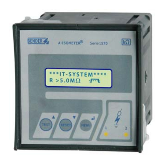
5. Operating and setting 5.1 Operating elements and displays IR157x 1 Two-line display for standard and menu mode TEST button: to call up the self test/ Up key: parameter change, moving up in the menu RESET button: to delete insulation fault messages / Down key: parameter change, moving down in the menu MENU button: activating the menu system / Enter key: confirmation parameter change... -
Page 22: Display In The Standard Mode
Operating and setting 5.1.1 Display in the standard mode Indication of the insulation resistance in kΩ Additional information about the insulation resis- tance: „+“ = insulation fault at L+ „–“ = insulation fault at L– „s“ = new measurement has started Measuring techniques: = Polarity of the measuring pulse (AMP, IR1575) Messages:... - Page 23 Operating and setting This function is only available after activating the fault memory in the ISO SETUP menu or after bridging R1/R2. Furthermore, the A-ISOMETER® can only be reset when the present insulation value is 25% higher than the preset response value. The menu system is called up by pressing the MENU key.
-
Page 24: Menu Structure
Operating and setting 5.2 Menu structure Switchover to the menu mode After pressing the MENU key, you can change from the standard mode to the menu mode. From the menu mode you can link to the different sub menus. Navigation within the menu Select the desired menu item using the UP/DOWN keys. -
Page 25: Diagram Menu Structure
Operating and setting 5.2.1 Diagram menu structure TGH1370en/12.2019... -
Page 26: Menu Iso Setup: Setting Of The Basic A-Isometer® Functions
Operating and setting 5.3 Menu ISO SETUP: Setting of the basic A-ISOMETER® functions All alarm functions such as Alarm 1 and Alarm 2 (prewarning and main alarm), the operating principle of the alarm relays K1 and K2 (N.O = N/O operation, N.C = N/C operation) and the fault storage are set in this menu. -
Page 27: Diagram Iso Setup
Operating and setting 5.3.3 Diagram ISO SETUP TGH1370en/12.2019... -
Page 28: Memory Setting (On/Off)
Operating and setting When a defect occurs at the A-ISOMETER®, the relay K2 will automa- tically be activated as a system fault relay. 5.3.4 Memory setting (on/off) Memory: on = Fault memory is activated The device must be reset with the RESET button after clearing the fault. -
Page 29: Menu Password
Operating and setting 5.4 Menu PASSWORD 5.4.1 Activating and setting the password This menu can be used to activate a "Password" query. This protects the A-ISOMETER® against unauthorized settings and modifications. The desired password (menu point 2. Password: xxx) can be set with the arrow keys and confirmed with the ENTER key. -
Page 30: Menu Language
Operating and setting 5.5 Menu LANGUAGE 5.5.1 Setting the national language This menu item offers a selection of two languages for the indication of fault messages. Choose between English and German language. The device menu is indicated in English language and cannot be changed by the language setting. -
Page 31: Menu Service
Operating and setting 5.6 Menu SERVICE This menu point is provided for the BENDER service personnel and is protected by a password against erroneous settings. It is intended to provide fast fault clearance by qualified experts in the event of a device error. - Page 32 Operating and setting TGH1370en/12.2019...
-
Page 33: Technical Data Ir1570/1575
6. Technical Data IR1570/1575 6.1 Data in tabular form Insulation coordination acc. to IEC 60664-1 Rated voltage ..........................AC 500 V Rated impulse voltage/pollution degree ..................4 kV / 3 Voltage ranges IR157x: Nominal voltage range U ................1AC / 3(N)AC 0…480 V Nominal frequency f ...................... - Page 34 Technical Data IR1570/1575 Measuring circuit Measuring voltage U ≤ ........................20 V Measuring current I (at R ≤ = 0 Ω).................... 170 μA Internal DC resistance R ≥ ......................119 kΩ Internal impedance Z ≥ at 50 Hz ....................114 kΩ Permissible extraneous DC voltage U ≤...
-
Page 35: Standards And Approvals
Technical Data IR1570/1575 Climatic class acc. to IEC 60721-3-3 ....................3K5 Operating mode....................... continuous operation Mounting ......................as indicated on the display Connection ........................screw terminals Connection, rigid/flexible..............0.2…4 mm / 0.2…2.5 mm Connection, flexible with connector sleeve, without/with plastic sleeve ....0.25…2.5 mm Conductor sizes (AWG)......................... -
Page 36: Characteristic Curves
Technical Data IR1570/1575 6.3 Characteristic curves A-ISOMETER response times in relation to system leakage capacitances of: = 1…20 μF, U = 0…460 V / 50 Hz = 1…60 μF, U = 0…460 V / 50 Hz TGH1370en/12.2019... - Page 37 Technical Data IR1570/1575 Max. AC voltage between the IT system and earth in the frequency range < 50 Hz 1000 [Hz] TGH1370en/12.2019...
-
Page 38: Dimension Diagram Enclosure Ir157X
Technical Data IR1570/1575 6.4 Dimension diagram enclosure IR157x suitable for the installation into control panel, the following illustration shows the necessary outbreak: TGH1370en/12.2019... -
Page 39: Ordering Details
Technical Data IR1570/1575 6.5 Ordering details 6.5.1 Standard version Nominal voltage n Supply voltage s Type Art.-No. AC 88…264 V 3(N)AC 0…480 V IR1570-435 AC 340…460 V B91044000 AC 0…480 V DC 77…286 V AC 88…264 V 3(N)AC 0…480 V IR1570W-435 AC 340…460 V B91044000W... -
Page 40: Label For Modified Versions
Technical Data IR1570/1575 6.5.2 Label for modified versions There will only be a label in this field if the A-ISOMETER is different from the standard version. TGH1370en/12.2019... - Page 41 INDEX Alarm LED 1 Language, selecting Alarm LED 2 Alarm relays, operating principle Menu - INFO Characteristic curves - ISO SETUP Commissioning flow chart - LANGUAGE - Navigation - PASSWORD - SERVICE Device characteristics - structure Directions for installation Display in the menu mode Display in the Standard mode Navigation within the menu Enclosure, dimension diagram...
- Page 42 INDEX Self test Standards System fault relay Technical data TEST button Wiring diagram, Isometer TGH1370en/12.2019...
- Page 44 Dipl.-Ing. W. Bender GmbH & Co.KG Londorfer Str. 65 • 35305 Gruenberg • Germany P.O. Box 1161 • 35301 Gruenberg • Germany Tel.: +49 (0)6401-807-0 Fax: +49 (0)6401-807-259 E-mail: info@bender-de.com Internet: http://www.bender-de.com...
Need help?
Do you have a question about the A-ISOMETER IR1570 Series and is the answer not in the manual?
Questions and answers