Table of Contents
Advertisement
Quick Links
Download this manual
See also:
Manual
Advertisement
Table of Contents

Related Manuals for Bender ISOMETER iso685-D-P


Summary of Contents for Bender ISOMETER iso685-D-P
- Page 1 Manual ISOMETER® iso685–D–P iso685W–D–P iso685–S–P iso685W–S–P Insulation Monitoring Device with integrated locating current injector for IT AC systems with galvanically connected rectifiers and inverters and for IT DC systems iso685-x-P_D00170_05_M_XXEN/05.2018...
- Page 2 Email: info@bender.de Web: www.bender.de Customer service: Service hotline: 0700-BenderHelp (Telephone and Fax) Carl-Benz-Straße 8 • 35305 Gruenberg • Germany © Bender GmbH & Co. KG Tel.:+49 6401 807-760 All rights reserved. Fax:+49 6401 807-629 Reproduction only with permission of the publisher.
-
Page 3: Table Of Contents
Table of contents 1. Important information ..............7 5. Mounting ..................19 1.1 How to use this manual ..........7 5.1 General instructions . - Page 4 Table of contents 8. Display ....................35 10.1 (1.10) Outputs ..........46 8.1 Standarddisplay .
- Page 5 Table of contents 10.1 (2.4.2) Outputs......... . . 51 10.1 (2.7) Inputs .
- Page 6 Table of contents 10.1 (6.3.4) Modbus/TCP ........57 14.
-
Page 7: Important Information
Bender devices This signal word indicates a medium risk of danger that can lead to • Extended guarantee for Bender devices, which includes an in-house repair service or death or serious injury if not avoided. replacement devices at no extra cost... -
Page 8: Customer Service
The dates of training courses and workshops can be found on the Internet at For more information on the disposal of Bender devices, refer to our homepage at www.bender-de.com -> Know-how -> Seminars. www.bender-de.com -> Service & Support. -
Page 9: Safety Instructions
Part of the device documentation in addition to this manual is the enclosed "Safety in- should be eliminated as quickly as possible. structions for Bender products". 2.2 Work activities on electrical installations. If the ISOMETER® is installed inside a control cabinet, the insulation fault message must be audible and/or visible to attract attention. -
Page 10: Intended Use
Safety instructions Safety instructions 2.4 Intended use Only qualified personnel are permitted to carry out the work necessary to install, commission and run a device or system. Read the manual before you begin to mount, connect, and commission the unit. Always keep the manual within easy reach for future reference following commissioning. -
Page 11: Function
It is universally applicable in AC, 3(N)AC, AC/DC and DC systems. AC systems may include (Webserver/Option: COMTRAXX® gateway) extensive DC-supplied loads (such as rectifiers, inverters, variable-speed drives). • Worldwide remote diagnosis via the Internet (made available by Bender Service only) 3.2.2 Special ISOMETER® characteristics •... -
Page 12: Function Description
Function Function 3.3 Function description The insulation monitoring device iso685–x–P is able to measure the insulation resistance reliably and precisely in all common IT systems (unearthed systems). Due to various ap- The insulation monitoring device continuously monitors the entire insulation resistance plications, system types, operating conditions, application of variable-speed drives, high of an IT system during operation and triggers an alarm when the value falls below a pre- system leakage capacitances etc., the measurement technique must be able to meet var-... -
Page 13: Insulation Fault Location
• BCOM for Bender device communication via Ethernet • BS bus for communication of Bender devices (RS-485) • BB bus for communication of Bender devices (Bender-internal device bus) • Integrated web server for reading out measured values and for parameter setting... -
Page 14: Compatibility With Eds Devices
Function Function 3.7 Compatibility with EDS devices Full compatibility, communication with ISOMETER® via BS bus Device Notes EDS440-L B91080202 EDS440-L EDS440W-L B91080202W EDS441-L B91080205 EDS441-L EDS441W-L B91080205W EDS441-LAB B91080207 EDS441-LAB EDS441W-LAB B91080207W EDS460/490L Not recommended for new systems EDS460/490D Not recommended for new systems EDS461/491L Not recommended for new systems EDS461/491D... -
Page 15: Device Overview
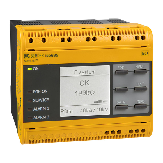
4. Device overview Device overview 4.2 Device variants 4.1 Dimensions iso685–D–P iso685–D–P The device version features a high-resolution graphical LC dis- play and control elements for direct operation of the device functions. It cannot be combined with an FP200. iso685–S–P The device variant ISOMETER®... -
Page 16: Connections And Panel
Panel PGH ON PGH ON Connection bottom REMOTE interface to connect to the FP200(W) * Optional expansion module (BB-Bus) for Bender devices (e.g. BB Bus) Bottom Multifunctional I/O interface (refer to Page ETH (X2) Ethernet interface Switchable terminating resistor for termination of the RS-485 interface... -
Page 17: Display Elements And Device Buttons
Device overview Device overview 4.4 Display elements and device buttons 4.4.2 Device buttons The device settings can be adjusted in the respective menu using the menu buttons. De- pending on the menu entry, one of the options displayed below is assigned to the but- tons. -
Page 18: Operation And Navigation
Device overview Device overview 4.5 Operation and Navigation 4.5.4 Character input Select the required character with the 4.5.1 Menu selection Ethernet 6.3.2 button (forwards) and the button (back- wards). To enter the next character, use the The menu is activated with the IT system 192. -
Page 19: Mounting
5. Mounting Mounting 5.1 General instructions Only qualified personnel are permitted to carry out the work necessary to install, commission and run a device or system. Read the manual before you begin to mount, connect, and commission the unit. Always keep the manual within easy reach for future reference following commissioning. -
Page 20: Screw Mounting
Mounting Mounting 5.2 Screw mounting 5.3 DIN rail mounting 1. Fix the three mounting clips delivered with the device (two of them packed 1. Fix the three mounting clips delivered with the device (two of them packed separately) manually or using a tool, as illustrated below. separately) manually or using a tool, as illustrated below. -
Page 21: Connection
6. Connection Connection 6.1 Connection requirements Provide line protection! Consider the minimum distance to adjacent devices: lateral 0 mm, top 20 mm, bottom According to IEC 60364-4-43, a line protection shall be provided for the 20 mm. supply voltage. CAUTION According to IEC 60364 (VDE 0100), only qualified personnel are permit- ted to carry out the work necessary to install, commission and run a de- Risk of injury from sharp-edged terminals! -
Page 22: Connection To A 3(N)Ac System
Connection Connection 6.2 Connection to a 3(N)AC system Check proper connection! Prior to commissioning of the installation, check that the device has been Risk of injury, fire and damage to property due to a short circuit! properly connected and check the device functions. Perform a functional According to DIN VDE 0100-430, devices used to protect against a short test using an earth fault via a suitable resistance. -
Page 23: Connection To An Ac System
Connection Connection 6.3 Connection to an AC system 6.4 Connection to a DC system Risk of injury, fire and damage to property due to a short circuit! Risk of injury, fire and damage to property due to a short circuit! According to DIN VDE 0100-430, devices used to protect against a short According to DIN VDE 0100-430, devices used to protect against a short circuit when terminals L1/+, L2 und L3/- are coupled to the IT system to be... -
Page 24: Connection To The Supply Voltage
Connection Connection 6.5 Connection to the supply voltage 6.6 Connection to the X1 inteface Danger of damage to property due to faulty connections! The device can be damaged if the unit is simultaneously connected to the supply voltage via the X1 interface and A1/+, A2/- terminals. I1 I2 I3 A B Do not connect the device simultaneously via X1, and A1/+, A2/- to differ- CAUTION... -
Page 25: Connection To The Ethernet Interface Eth
Connection Connection 6.7 Connection to the Ethernet interface ETH 6.9 Position the terminal covers and click it into place RJ45 Connect to other ISOMETER®s with a RJ45 plug or network several ISOMETER® in a STAR topology by means of a switch. (refer to 12. -
Page 26: Connection To The Bb Bus
Observe the maximum output current! For devices connected to the BB-Bus: The maximum output current is re- The BB bus is an interface that enables Bender devices to communicate with each other. duced according to the formula for the calculation of I . -
Page 27: Connection Example Isometer® To Eds
Connection 6.11.1 Connection example ISOMETER® to EDS to loads to loads to loads to loads L1 L2 L3 L4 L5 L6 L7 L8 L9 L10 L11 L12 l1 l2 l3 l4 l5 l6 l7 l8 l9 l10 l11 l12 L1/+ A1/+ A2/- L3/- KE E... -
Page 28: Connection To A 3(N)Ac System
Connection 6.11.2 Connection to a 3(N)AC system to loads to loads l1 l2 l3 l4 l5 l6 l7 l8 l9 l10 l11 l12 A1/+ A2/- L1/+ L3/- KE E k1 k2 k3 k4 k5 k6 k7 k8 k9 k10 k11 k12 11 12 EDS440 ISOSCAN®... -
Page 29: Connection To An Ac System
Connection 6.11.3 Connection to an AC system to loads to loads l1 l2 l3 l4 l5 l6 l7 l8 l9 l10 l11 l12 A1/+ A2/- L1/+ L3/- KE E k1 k2 k3 k4 k5 k6 k7 k8 k9 k10 k11 k12 9 10 11 12 EDS440 ISOSCAN®... -
Page 30: Connection To A Dc System
Connection 6.11.4 Connection to a DC system L– to loads to loads l1 l2 l3 l4 l5 l6 l7 l8 l9 l10 l11 l12 A1/+ A2/- k1 k2 k3 k4 k5 k6 k7 k8 k9 k10 k11 k12 L1/+ L3/- KE E 11 12 EDS440... -
Page 31: System Structure
Connection 6.11.5 System structure AC 24 V DC 110 V Input Output A1/+ A2/- L1/+ L3/- KE E EDS441 EDS440 ISOSCAN® ISOSCAN® IT-System PGH ON >20 MΩ >20 MΩ R(an) 40kΩ/10kΩ iso685-x-P_D00170_05_M_XXEN/05.2018... -
Page 32: Commissioning
7. Commissioning Commissioning 7.1 General initial commissioning process Commissioning the System commissioning Commissioning the ® ® EDS44x ISOMETER ISOMETER with EDS44x 1. Check that the ISOMETER® is properly connected to the system to be monitored. Connect the system vol- The ON LED flashes until Connect the supply vol- 2. -
Page 33: Initial Commissioning
Commissioning Commissioning 7.3 Initial commissioning 7.3.3 Set system type By setting the system type the insulation monitoring device can be optimally adapted to Check network function! the system to be monitored. The system type is essential information for the insulation When the device has been integrated into a network, the impact on the monitoring device in order to determine the insulation resistance correctly. -
Page 34: Setting Eds Current
Commissioning Commissioning 7.3.6 Setting EDS current 7.4 Commissioning EDS Set the maximum locating current. Proceed as follows to put into operation an EDS after commissioning the ISOMETER®: EDS441: 1-5 mA 1. First, search for all available measuring channels. Menu path: Menu/EDS/Scan channels. EDS440: 10-50 mA For further information, refer to “Current”... -
Page 35: Recommissioning
Commissioning Commissioning 7.5 Recommissioning If the device has already been put into operation once, the self test will be carried out shortly after connecting the supply voltage. The commissioning wizard will not restart. The commissioning-assistent wizard can be manually started using the menu path: Menu/Device settings/Commissioning This menu can be used to modify settings made previously. -
Page 36: Display
8. Display Display 8.1 Standarddisplay 8.2 Fault display (active) In normal operation, the ISOMETER® displays the message OK and below the latest An active fault is displayed by measured insulation resistance. The upper part of the display becomes orange and displays the fault message. Depending on the type of fault, the LEDs ALARM 1, ALARM 2 or SERVICE are activated. -
Page 37: Fault Display (Inactive)
Display Display 8.3 Fault display (inactive) If several fault messages occur, you can navigate through the faults using the buttons. In addition to the type of fault and the associated alarm value, you can see when An inactive fault is displayed by . -
Page 38: Acknowledging A Fault Message
Display Display 8.4 Acknowledging a fault message 8.5 Data-isoGraph In order to acknowledge the fault message and return to the ISOMETER®'s standard dis- The isoGraph represents the chronological sequence of the insulation resistance over play, all faults must be acknowledged by means of the reset button . time. -
Page 39: History Memory
Display Display 8.6 History memory 8.7 Initial measurement Up to 1023 alarm messages and device errors are stored in the history memory with date During the initial measurement, the device records all measured values. and time stamp. When the history memory is deleted, the minimum insulation resistance All measured values that may have been recorded before will be discarded if a new initial will also be reset under Menu/ Data Measured values - Data insulation - Reset. -
Page 40: Isonet Mode
Display Display 8.8 ISOnet mode 8.9 Automatic test The ISOMETER® displays the message "ISOnet active" when the ISOMETER® is in ISOnet A blinking "ON" LED and the bar indicating the measurement progress is pulsing (see mode, but it does not make any measurements. bottom right of the display) indicates that the ISOMETER®... - Page 41 8.10 Insulation fault location Display When EDS mode is activated, the ISOMETER® indicates the message "Ins. fault locat.". Insulation fault location in auto mode and 1 cycle. Below, on the left side it indicates which EDS mode is activated. On the right side it indica- tes the polarity change of the measuring pulses including the pause in between.
-
Page 42: Menu Structure
Settings Settings 9. Settings 2. EDS 1. General 1. Current 9.1 Menu structure 2. Mode 3. Use portable EDS 1. Alarm settings 1. Insulation alarm 1. Alarm 1 2. Scan for Channels 2. Alarm 2 3. Enable Channel 3. Memory 4. -
Page 43: Settings
Settings Settings 9.2 Settings in the device menu 3. Data meas. values 4. Control Representation of the menu items in the chapter headings 5. History The ISOMETER® settings will be explained in the order corresponding to 6. Device settings 1. Language the device menu. -
Page 44: 1) Alarm 1
0.1…460 Hz. The DC alarm is triggered in the event of a DC offset voltage. •on Allows Bender service to make customer-specific settings •Customer specific The DC alarm is NOT triggered in the event of a DC offset voltage. •off (1.4) System type... -
Page 45: (1.6) Device
Settings Settings (1.6) Device (1.9.1) Digital 1 Set the ISOMETER® insulation resistance measurement function to active or inactive: The following parameters can be set for the digital input: The device is active. (1.9.1.1) Mode •Active The device DOES NOT measure the insulation resistance, the mes- •Inactive The operating mode for the digital input can be set to the following values: sage... -
Page 46: 4) Function
Settings Settings (1.9.1.4) Function (1.10) Outputs The ISOMETER® digital input functions can be configured differently: The ISOMETER® provides a total of six outputs: The following parameters can be set for the outputs: Digital input without function •off (1.10.1) Relay 1 Device self test •TEST Reset of fault and alarm messages... -
Page 47: (1.10.1.4) Function 2
Settings Settings Select the appropriate setting for function 1. The following parameters can be set. •Device fault The status of the output changes in the event of an internal device The function is not used. •off error. The status of the output changes when the value falls below the set •Ins. -
Page 48: (1.10.3.2) Mode
Settings Settings (1.10.3.2) Mode (1.10.4) Digital 2 The following settings can be used to set the operating mode for the digital output: Refer to “9.2 (1.10.3) Digital 1”. (1.10.5) Buzzer In the active mode +24 V will be internally applied across the Qx •Active output. -
Page 49: (1.10.6.2) Midscale
Settings Settings (1.10.6.2) Midscale (1.10.6.4) Function Select the appropriate midscale. The following parameters can be set: Select the appropriate setting for the analogue output. The following parameters can be set. The switching signal is linear to the insulation resistance in the indi- •Linear cated measuring range. -
Page 50: (2.1.2) Mode
Settings Settings (2.1.2) Mode (2.1.3) Using a portable EDS To locate insulation faults, select one of the three available modes for insulation fault If you would like to use a portable EDS, activate this function here. After that, the insula- location. -
Page 51: (2.4) Group Settings
Settings Settings (2.4) Group settings (2.4.1.2) CT monitoring Use group settings to adjust the settings for several EDS or EDS channels simultaneously Activate or deactivate the CT monitoring. or to read out settings. If CT monitoring is active, an alarm is signalled as soon as a fault occurs on a current trans- If you would like to make settings for each EDS or each EDS channel individually, then former of an activated channel (short circuit or interruption). -
Page 52: Function 3
Settings Settings (2.4.2.1) Relays Set the function for the outputs: Select the relays that you would like to configure. •off The function is not used. The status of the output changes if an insulation fault is detected •I •Select all All relays are selected. -
Page 53: Inputs
Settings Settings 2.4.2.2.3 Function 2 (2.4.3.1) Mode Refer to “9.2 2.4.2.1.3 Function 1”. The operating mode for the digital input can be set to the following values. For a descrip- tion of the operating modes, refer to “Mode” on page 45. -
Page 54: T(On)
Settings Settings (2.4.4.2) Frequency (2.5) Channel In this menu, each channel can be configured. Also refer to “9.2 (2.4.1) Channel”. Settings made to this menu point will only have an effect on connected (2.5.1) Name EDS460 and NOT on EDS44x devices. Enter a name for the selected channel. -
Page 55: T(Off)
In this menu, each digital output can be configured. (2.9) Service Also refer to “9.2 (2.4.2.3) Digital output”. The service menu can only be accessed by Bender Service staff. (2.6.3.1) TEST (3.0) Data measured values Refer to “9.2 2.4.2.3.1 TEST”. -
Page 56: History
Settings Settings (5.0) History (6.2.3) Summertime In the history menu, the faults detected by the ISOMETER® are displayed. For a detailed Summer time can be considered in the following settings: function description refer to “History memory” on page No automatic change between summer time and standard time. •off Overview of faults that have occurred. -
Page 57: Summertime
Settings Settings (6.2.8) UTC (6.3.2.4) Std. GW (manual configuration) Configure the time according to UTC (Coordinated Universal Time) For Germany, set +1 If a standard gateway is used in your network, enter its IP address here. If there is no gate- for wintertime (CET) and +2 for summer time (CEST). -
Page 58: 4) Modbus/Tcp
(6.3.5) BS-Bus / RS-485 In the data backup menu device settings can be saved or device settings already saved Set the parameters for communication with other devices via the Bender sensor bus. can be restored. For further information, refer to “BS bus”... -
Page 59: Device Communication
• Easy assignment and editing options for devices manuals. • Maintenance • Data storage of specific events for fast support by Bender Service. A maximum of 5 TCP/IP connections can be used simultaneously. A maximum of 5 TCP/IP connections can be used simultaneously. -
Page 60: Web Server User Interface
Device communication Device communication 10.4.2 Web server device menu (first level) Write access is deactivated by default in the device menu (= Deny). To set parameters via the web server, write access must first be activated in the isoHR685W–D ISOMETER® device menu (= Allow) (see “Write access”... -
Page 61: Bs Bus
The optimum cable routing for the BS bus is a double-terminated bus topology. The The BS bus is used to extend Bender measuring devices (e.g. ISOMETER®) It is an RS-485 in- length of the branch line is limited to 1 m. These branch lines do not have to be terface with a specially developed protocol for Bender devices. -
Page 62: Device Profiles
– – – – – are made by Bender service, then the profile has the same parameters as the "Power circuits" profile. For response times, see “Diagrams” on page * Low frequency mains voltage When another profile is selected, the value of R is reset. -
Page 63: Special Functions For Coupled It Systems
12. Special functions for coupled IT systems Special functions for coupled IT systems 12.1 Particularities when monitoring coupled IT systems 12.2 System isolation via digital input with two coupled systems When using ISOMETER®s in IT systems, make sure that only ONE active ISOMETER® is con- The coupling switch must have a free contact so that the ISOMETER®... -
Page 64: System Separation Via Isonet
Special functions for coupled IT systems Special functions for coupled IT systems 12.3 System separation via ISOnet 12.3.1 System structure IT-System 1 IT-System 2 The ISOnet function ensures via an Ethernet connection that only one ISOMETER® of the interconnection is active when several ISOMETER®s are connected to an IT system. For several ISOMETER®s to be able to measure in the same ISOnet inter- BCOM BCOM... -
Page 65: Configuration And Function
Special functions for coupled IT systems Special functions for coupled IT systems 12.3.2 Configuration and function For the ISOnet function, the following settings are made in the menu: Alarm settings -> ISONet -> ISONet = BCOM. The ISOnet function of all ISOMETER®s existing in the system has to be activated and the number of devices has to be determined - this can be carried out in the menu Alarm settings ->Number of participants. -
Page 66: Insulation Fault Location
13. Insulation fault location Insulation fault location 13.1 General description 13.4 Starting and stopping the insulation fault location An additional function of the ISOMETER® in combination with the EDS is the selective in- The insulation fault location can be started and stopped via different interfaces: sulation fault location. -
Page 67: Diagrams
14. Diagrams Diagrams 14.1 Response time profile power circuits 14.3 Response time profile generator Response time as a function of the response value and system leakage Response time as a function of the response value and system leakage capacitance according to IEC 61557-8 ( = 690 V, f = 50 Hz) measuring capacitance according to IEC 61557-8 ( = 690 V, f = 50 Hz) measuring... -
Page 68: Response Time Profile Inverter > 10 Hz
Diagrams Diagrams 14.5 Response time profile inverter > 10 Hz 14.7 Response time DC Alarm Typical response times for DC alarm for RF depending on system profile and Response time as a function of the response value and system leakage system leakage capacitance capacitance according to IEC 61557-8 ( = 690 V, f = 50 Hz) measuring... -
Page 69: Alarm Messages
• Press the test button page 21 flash in common mode Service mode active! The device is in maintenance condition • Contact Bender Service SERVICE lights up • Check measured system capacitance or system frequency in the Profile does not suit the Info menu Wrong profile selected for this application “Profile”... -
Page 70: Alarm Messages Of The Eds
Alarm messages Alarm message Description Actions Reference LED indicators DC offset voltage There is a DC offset voltage in the system. • Check insulation fault and eliminate fault of DC components. “DC alarm” on page 44 Operating outside the specified supply voltage Undervoltage •... -
Page 71: Factory Settings
16. Factory settings Factory settings Parameter Value Parameter Value Response values/alarms Switching elements Response value R (ALARM 1) 40 kΩ Relay 1 Response value R (ALARM 2) 10 kΩ Test DC alarm Relay mode N/C operation DC-offset voltage for DC alarm 65 V Function 1 Ins. -
Page 72: Technical Data
17. Technical data Technical data 17.1 Tabular data Supply via X1: Supply voltage U ....................................DC 24 V Insulation coordination acc. to IEC 60664-1/IEC 60664-3 Tolerance of U ................................DC -20…+25 % Definitions: IT system being monitored Measuring circuit (IC1)..............................L1/+, L2, L3/- Nominal system voltage range U ............................AC 0…690 V Supply circuit (IC2) .................................. - Page 73 Technical data Technical data Display Interfaces Indication........................graphic display 127 x 127 pixels, 40 x 40 mm Field bus: Display range measured value............................0.1 kΩ…20 MΩ Interface/protocol........................... Web server/Modbus TCP/BCOM Operating uncertainty (acc. to IEC 61557-8).........................±15%, min. 1 kΩ Data rate................................10/100 Mbit/s, autodetect Max.
-
Page 74: Device Feature W
Technical data Technical data Environment/EMC and temperature range Other EMC....................................IEC 61326-2-4 Operating mode continuous operation Operating temperature................................ -25…+55 °C Mounting (0°) display oriented, cooling slots must be ventilated vertically Transport....................................-40…+85 °C Degree of protection internal components ............................IP40 Long-term storage ................................-40…+70 °C Degree of protection terminals ................................IP20 Classification of climatic conditions acc. -
Page 75: Standards And Certifications
Technical data Technical data 17.3 Standards and certifications 17.4.3 Insulation fault locators The ISOMETER® has been developed in compliance with the following standards: Supply voltage U Type Response value Art. no. • DIN EN 61557-8 (VDE 0413-8):2015-12 EDS440-S-1 AC/DC 24…240V 2…10mA B 9108 0201 EDS440W-S-1... -
Page 76: Glossary
18. Glossary The BB bus is an interface which enables Bender devices to communicate with each other (Bender-internal device bus). BB bus The BB bus can be used with an ISOMETER® and one or more EDS44…-S. BCOM Protocol for communication between Bender devices via an IP-based network. -
Page 77: Index
Index Index Connections and panel Accessories DC system Hazards when handling the device Alarm Ethernet interface History memory Alarm 1 Relay 1 interface (11 12 14) Alarm 2 Supply voltage Alarm settings Initial measurement Connection to a 3(N)AC system Anzeige Inputs Control circuits Messpuls... - Page 78 Index Index Profile power circuits Relative uncertainty Mains voltage 11, 72 Response value Measured values IΔL Menu Messpuls Minimum current rectifier Safety instructions Minimum distance Self test Modbus TCP 55, 58 Service menu Mounting 43, 63 Settings DIN rail mounting Alarm Screw mounting Basic settings...
- Page 79 Notes Index iso685-x-P_D00170_04_M_XXEN/01.2018...
- Page 80 Londorfer Straße 65 • 35305 Grünberg • Germany Carl-Benz-Straße 8 • 35305 Grünberg • Germany Tel.: +49 6401 807-0 Tel.: +49 6401 807-760 Fax: +49 6401 807-259 Fax: +49 6401 807-629 E-Mail: info@bender.de E-Mail: info@bender-service.com Web: www.bender.de Web: http://www.bender.de Group Fotos: Bender Archiv und bendersystembau Archiv.
Need help?
Do you have a question about the ISOMETER iso685-D-P and is the answer not in the manual?
Questions and answers