Bender ISOMETER isoES425 Manual
Insulation monitoring device for unearthed ac-, ac/dc and dc systems for energy storage devices up to ac/dc 400v
Hide thumbs
Also See for ISOMETER isoES425:
- Quick start manual (41 pages) ,
- Manual (24 pages) ,
- Quick start manual (9 pages)

Related Manuals for Bender ISOMETER isoES425


Summary of Contents for Bender ISOMETER isoES425
- Page 1 Manual EN ISOMETER® isoES425 Insulation monitoring device for unearthed AC-, AC/DC and DC systems for energy storage devices up to AC/DC 400 V Software version: D0471 V1.xx isoES425_D00214_01_M_XXEN/10.2023...
- Page 2 isoES425_D00214_01_M_XXEN/10.2023...
-
Page 3: Table Of Contents
Indication of important instructions and information...............5 Signs and symbols............................5 Service and Support............................5 Training courses and seminars........................6 Delivery conditions............................6 Inspection, transport and storage......................6 Warranty and liability.............................6 Disposal of Bender devices..........................7 1.10 Safety..................................7 Function.......................8 Intended use..............................8 Device features..............................8 Functional description........................... 9 2.3.1... - Page 4 Table of contents Operating and display elements......................18 Menu overview...............................20 Displaying measured values........................21 Setting the response values (AL)......................21 4.4.1 Setting the response values for monitoring the insulation resistance........21 4.4.2 Setting the response values for undervoltage and overvoltage..........22 4.4.3 Response values overview.........................22 Configuring fault memory, alarm relays, and interfaces (out)............23 4.5.1 Configuring the relays..........................23...
-
Page 5: General Information
Protect from dust Temperature range Recycling RoHS directives Service and Support Information and contact details about customer service, repair service or field service for Bender devices are available on the following website: Fast assistance | Bender GmbH & Co. KG. isoES425_D00214_01_M_XXEN/10.2023... -
Page 6: Training Courses And Seminars
Regular face-to-face or online seminars for customers and other interested parties: www.bender.de > know-how > seminars. Delivery conditions The conditions of sale and delivery set out by Bender GmbH & Co. KG apply. These can be obtained in printed or electronic format. The following applies to software products: ‘Software clause in respect of the licensing of standard software as part of deliveries,... -
Page 7: Disposal Of Bender Devices
ISOMETER® isoES425 Disposal of Bender devices Abide by the national regulations and laws governing the disposal of this device. For more information on the disposal of Bender devices, refer to www.bender.de > service & support. 1.10 Safety If the device is used outside the Federal Republic of Germany, the applicable local standards and regulations must be complied with. -
Page 8: Function
• Two separately adjustable response value ranges 1…990 k (prewarning, alarm) • RS-485 (galvanically isolated) including the following protocols: – BMS (Bender measuring device interface) for the data exchange with other Bender devices – IsoData (for continuous data output) • Password protection against unauthorised changing of parameters... -
Page 9: Functional Description
ISOMETER® isoES425 Functional description The ISOMETER® measures the insulation resistance R and the system leakage capacitance C between the system to be monitored (L1/+, L2/–) and earth (PE). The RMS value of the system voltage U between L1/+ and L2/– as well as the residual voltages U (between L1/+ and earth) and U (between L2/–... -
Page 10: Undervoltage/Overvoltage Monitoring
Function 2.3.2 Undervoltage/overvoltage monitoring To monitor the system voltage U , the two parameters “U˂” and “U˃” can be enabled in the response-value menu “AL” (chapter 4.4). The maximum undervoltage value is limited by the overvoltage value. The RMS value of the system voltage U is monitored. -
Page 11: Connection Monitoring
(“Err”) will be signalled, “E.xx” appears on the display as an identifier for error type xx, and the LEDs “ON”/“AL1”/“AL2” will flash. Please contact Bender Service, if the error occurs again after the device has been restarted or the factory settings have been restored. -
Page 12: Measuring And Response Times
Function The message “S.AL” indicates a device start with alarm. When the parameter value is set to “S.AL = on” and the supply voltage U is connected, the ISOMETER® starts with the insulation measured value R and sets all activated alarms. The alarms will be cleared only when the measured values are up-to-date and no thresholds are violated. -
Page 13: External Test/Reset Button (T/R)
The ISOMETER® uses the serial hardware interface RS-485 with the following protocols: • BMS The BMS protocol is an essential component of the Bender measuring device interface (BMS bus protocol). Data transmission generally makes use of ASCII characters. • IsoData The ISOMETER®... - Page 14 Function With “Adr = 0”, the menu entries baud rate and parity are not shown in the menu and the IsoData protocol is activated. With a valid bus address (i.e. not equal to 0), the menu item “baud rate” is displayed in the menu. The parameter value “---”...
-
Page 15: Installation, Connection And Commissioning
ISOMETER® isoES425 Installation, connection and commissioning Dimensions 45 70.5 31.1 47.5 74.5 Figure: Dimension diagram (in mm) Installation Figure: DIN rail mounting (left) or screw mounting (right) isoES425_D00214_01_M_XXEN/10.2023... -
Page 16: Connection
Installation, connection and commissioning Connection DANGER Risk of fatal injury due to electric shock! Touching live parts of the system carries the risk of: • Risk of electrocution due to electric shock • Damage to the electrical installation • Destruction of the device Before installing the device and before working on its connections, make sure that the installation has been de-energised. -
Page 17: Commissioning
ISOMETER® isoES425 Commissioning Check that the ISOMETER® is properly connected to the system to be monitored. Connect supply voltage U to the ISOMETER®. The device carries out a calibration, a self test and adjusts itself to the IT system to be monitored. With high system leakage capacitances this process may take up to 4 min. -
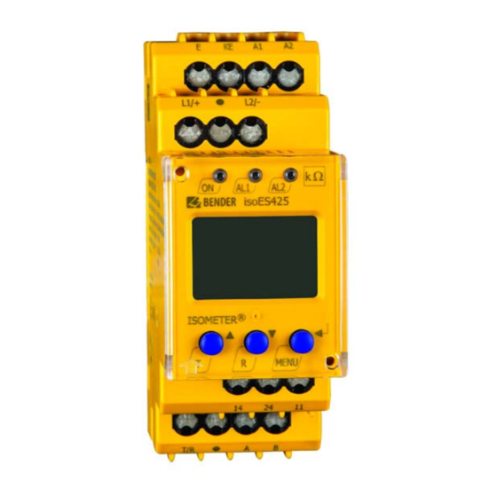
Page 18: Operation
Operation Operation Operating and display elements Device front Operating elements Function Power LED AL1 AL2 Alarm LEDs (For codes see “Assigning the alarm messages to the relays”, page 23.) Up and down buttons – For navigating up or down in the menu settings. - Page 19 ISOMETER® isoES425 Display Display elements Function System voltage U Insulation resistance R System leakage capacitance C Monitored conductors L1 L2 Voltage type DC Pulse symbol: error-free measured value update Voltage type AC °C Measured values and units μ n F Hz k M Ω...
-
Page 20: Menu Overview
Operation Menu overview Measurement display Menu selection Parameter selection Menu item Parameter Querying and setting response values Configuring fault memory, alarm relays and interface Setting delay times and self test cycles Setting device control parameters Querying software version Querying and clearing the history memory Going to the next-higher menu level isoES425_D00214_01_M_XXEN/10.2023... -
Page 21: Displaying Measured Values
ISOMETER® isoES425 Displaying measured values Overview Display Description Insulation resistance R ✓ ± R k 1 k … 4 M System leakage capacitance C ✓ C µF 0 µF … 105 µF System voltage U (L1 - L2) ✓ ~ ± U L1 L2 V …... -
Page 22: Setting The Response Values For Undervoltage And Overvoltage
Operation 4.4.2 Setting the response values for undervoltage and overvoltage How to proceed Open menu “AL”. Select parameter “U<” for undervoltage or parameter “U>” for overvoltage. Set value and confirm with Enter. 4.4.3 Response values overview Display Activation Setting value Description Range Prewarning value R... -
Page 23: Configuring Fault Memory, Alarm Relays, And Interfaces (Out)
ISOMETER® isoES425 Configuring fault memory, alarm relays, and interfaces (out) Call up menu „out“ to configure fault memory, alarm relays, and interfaces. 4.5.1 Configuring the relays Relay K1 Relay K2 Description Display Display Relay operating mode n/c or n/o FAC Factory settings Customer settings 4.5.2 Assigning the alarm messages to the relays... -
Page 24: Activating Or Deactivating Fault Memory
Operation K1 “r1” K2 “r2” LEDs Description Display Display Device start with alarm S.AL S.AL FAC Factory settings Customer settings LED off LED flashes LED on 4.5.3 Activating or deactivating fault memory Display Description Memory function for alarm messages (fault memory) FAC Factory settings Customer settings 4.5.4... -
Page 25: Setting Device Control Parameters (Set)
System connection test S.Ct Device test at device start Restore factory settings For Bender Service only FAC Factory settings Customer settings Reset to factory settings All settings with the exception of the interface parameters are reset to the factory settings. -
Page 26: Data Access Via Rs-485 Interface
Data access via RS-485 interface Data access via RS-485 interface Data access using the BMS protocol The BMS protocol is an essential component of the Bender measuring device interface (BMS bus protocol). Data transmission generally makes use of ASCII characters. BMS channel no. -
Page 27: Isodata Data String
ISOMETER® isoES425 IsoData data string In IsoData mode the ISOMETER® sends the entire data string roughly once per second. Communication with the ISOMETER® in this mode is not possible and no additional sender may be connected via the RS-485 bus cable. -
Page 28: Technical Data
Technical data Technical data Technical data isoES425 ( )* = factory setting Insulation coordination acc. to IEC 60664-1/-3 Definitions Measuring circuit (IC1) L1/+, L2/– Supply circuit (IC2) A1, A2 Output circuit (IC3) 11, 14, 24 Control circuit (IC4) E, KE, T/R, A, B Rated voltage 400 V Overvoltage category... - Page 29 ISOMETER® isoES425 Supply voltage Supply voltage U AC 100…240 V DC 24…240 V Tolerance of U –30…+15 % Frequency range of U 47…63 Hz Power consumption ≤ 3 W, ≤ 9 VA Monitored IT system Nominal system voltage U 3(N)AC, AC/DC 0…400 V Tolerance of U +25 % Frequency range of U...
- Page 30 Technical data Time response Response time t of R = 0.5 × R and C = 1 F nach IEC 61557-8 ≤ 10 s Start-up delay t 0…10 s (0 s)* Response delay t 0…99 s (0 s)* Delay on release t 0…99 s (0 s)* Displays, memory Display...
- Page 31 ISOMETER® isoES425 Switching elements Switching elements 2 × 1 n/o contacts, common terminal 11 Operating principle n/c, n/o (n/o)* Electrical endurance 10,000 cycles Contact data acc. to IEC 60947-5-1 Utilisation category AC-12 / AC-14 / DC-12 / DC-12 / DC-12 Rated operational voltage 230 V / 230 V / 24 V / 110 V / 220 V Rated operational current...
-
Page 32: Connection
The ISOMETER® was developed in compliance with the standards specified in the Declaration of Conformity. EU Declaration of Conformity Hereby, Bender GmbH & Co. KG declares that the device covered by the Radio Directive complies with Directive 2014/53/EU. The full text of the EU Declaration of Conformity is available at the following Internet address: https://www.bender.de/fileadmin/content/Products/CE/CEKO_isoXX425.pdf... -
Page 33: Ordering Data
ISOMETER® isoES425 Ordering data ISOMETER® Model Nominal system voltage U Article number Push-wire Screw-type terminals terminals isoES425-D4-4 3(N)AC, AC/DC 0…400 V B71037020 Accessories Description Article number Mounting clip for screw mounting B98060008 XM420 mounting frame B990994 Change log Date Document Valid from State/Changes version... - Page 34 isoES425_D00214_01_M_XXEN/10.2023...
- Page 35 ISOMETER® isoES425 isoES425_D00214_01_M_XXEN/10.2023...
- Page 36 Alle Rechte vorbehalten. 35305 Grünberg Nachdruck und Vervielfältigung nur mit Germany Genehmigung des Herausgebers. © Bender GmbH & Co. KG, Germany Subject to change! The specified Tel.: +49 6401 807-0 All rights reserved. standards take into account the edition info@bender.de Reprinting and duplicating only with valid until 10.2023 unless otherwise...
Need help?
Do you have a question about the ISOMETER isoES425 and is the answer not in the manual?
Questions and answers