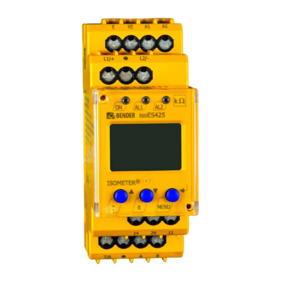
Bender ISOMETER isoES425 Manual
Insulation monitoring device for unearthed ac, ac/dc and dc systems (it systems) for energy storage devices up to ac/dc 400 v
Hide thumbs
Also See for ISOMETER isoES425:
- Quick start manual (41 pages) ,
- Manual (36 pages) ,
- Quick start manual (9 pages)

Related Manuals for Bender ISOMETER isoES425


Summary of Contents for Bender ISOMETER isoES425
- Page 1 Manual ISOMETER® isoES425 Insulation monitoring device for unearthed AC, AC/DC and DC systems (IT systems) for energy storage devices up to AC/DC 400 V Software version: D0471 V1.xx isoES425_D00214_00_M_XXEN/01.2019...
- Page 2 E-mail: info@bender.de Web: www.bender.de Customer service Service hotline: 0700-BenderHelp (Telephone and Fax) Carl-Benz-Strasse 8 • 35305 Gruenberg • Germany © Bender GmbH & Co. KG Tel.:+49 6401 807-760 All rights reserved. Fax:+49 6401 807-629 Reprinting only with permission of the publisher.
-
Page 3: Table Of Contents
Table of Contents 1. Important information ..............5 3.2.12 History memory HiS ......... . 12 3.2.13 Interface/protocols. -
Page 4: Important Information
CAUTION • Hardware and software update for Bender devices • Delivery of replacement devices for faulty or incorrectly delivered Bender devices This symbol denotes information intended to assist the user in making opti- • Extended warranty for Bender devices with in-house repair service or replacement mum use of the product. -
Page 5: Field Service
In the event of damage in transit, please products contact Bender immediately. The devices must only be stored in areas where it is protect- ed from dust, humidity and spray or dripping water, and in which the specified storage •... -
Page 6: Disposal
13th August 2005 must be taken back by the manufacturer and disposed of properly. For more information on the disposal of Bender devices, refer to our website at www.bender-de.com -> Service & support. -
Page 7: Safety Instructions
2.3 Intended use Part of the device documentation in addition to this manual is the enclosed "Safety in- structions for Bender products". Only qualified personnel are permitted to carry out the work necessary to in- 2.2 Work activities on electrical installations stall, commission and run a device or system. -
Page 8: Function
R and C relation that varies considerably. BMS interface (Bender measuring device interface) for data exchange with other • It is possible to assign the detected fault or the faulty conductor to an alarm relay via the Bender components menu. -
Page 9: Monitoring Of The Insulation Resistance
Function Function 3.2.1 Monitoring of the insulation resistance Error codes If, contrary to expectations, a device error should occur, error codes will appear on the The two parameters "R1" and "R2", which monitor the insulation resistance R , can be display. -
Page 10: Connection Monitoring
If the error occurs again after restarting the device or after restoring the factory settings, measuring times. please contact Bender service. An alarm will only be signalled when a threshold value of the respective measuring value is violated for the period of t without interruption. -
Page 11: Password Protection (On, Off)
The ISOMETER® uses the serial hardware interface RS-485 with the following protocols: s) in the parameter "t" is suppressed. • BMS The BMS protocol is an essential component of the Bender measuring device interface 3.2.8 Password protection (on, OFF) (BMS bus protocol). ASCII characters are used for data transfer. -
Page 12: Installation, Connection And Commissioning
4. Installation, connection and commissioning Installation, connection and commissioning Dimension diagram, sketch for screw mounting and push-wire terminal connection: Only qualified personnel are permitted to carry out the work necessary to Zubehör install, commission and run a device or system. Klick Risk of electrocution due to electric shock! Touching live parts of the system carries the risk of:... - Page 13 L1/+ L2/- L1/+ Test / Reset A1 A2 L1/+ L2/- isoES425 < ISOMETER MENU COM465IP RS-485 Fig. 4.1: Wiring diagram of the isoES425 For details about the conductor cross sections required for wiring, refer to the technical data from Page isoES425_D00214_00_M_XXEN/01.2019...
-
Page 14: Commissioning
Installation, connection and commissioning Installation, connection and commissioning Wiring diagram legend: 4.3 Commissioning Terminal Connections 1. Check that the ISOMETER® is properly connected to the system to be monitored. Connection to the supply voltage U via fuse (line protection): 2. Connect the supply voltage U to the ISOMETER®. -
Page 15: Operating The Device
5. Operating the device Operating the device The menu structure is illustrated schematically on the following pages. 5.1 Display elements in use After pressing the "MENU" button for > 1.5 s, the first menu item "AL" appears. Use Device front/display Function (Enter) buttons for navigation and settings. -
Page 16: Menu Overview
Operating the device Operating the device 5.2 Menu overview 5.3 "AL" menu Measurement display 5.3.1 Response value setting Standard display Menu selection Menu The two parameters that monitor the insulation resistance R , "R1" and "R2", can be found in the response value menu "AL". The value R1 can only be set higher than the value R2. If the insulation resistance R reaches or falls below the values R1 or R2, this leads to an alarm message. -
Page 17: Out" Menu
Operating the device Operating the device 5.4 "out" menu 5.4.3 Fault memory configuration Display Description 5.4.1 Configuration of the relay operating mode Memory function for alarm messages (fault memory) Relay K1 Relay K2 Description FAC = Factory settings; Cs = Customer settings Display Display 5.4.4 Interface configuration... -
Page 18: T" Menu
Insulation resistance Restore factory settings 1 kΩ … 4 MΩ Resolution 1 kΩ For Bender service only is an approximate value for asymmetrical insula- U R = kΩ tion faults and can be used as a trend indicator with FAC = Factory settings; Cs = Customer settings short measuring times. -
Page 19: Data Access Using The Bms Protocol
6. Data access using the BMS protocol Data access using the BMS protocol The BMS protocol is an essential component of the Bender measuring device interface (BMS bus protocol). ASCII characters are used for the data transfer. BMS channel no. -
Page 20: Isodata Data String
7. IsoData data string IsoData data string In IsoData mode, the ISOMETER® continuously sends the whole data string with a cycle time of approximately 1 s. Communication with the ISOMETER® in this mode is not possi- ble and no additional sender may be connected via the RS-485 bus cable. IsoData is activated in the "out"... -
Page 21: Technical Data
8. Technical data Technical data 8.1 Tabular presentation Measuring circuit Measuring voltage ..............................±12 V ( )* = Factory settings Measuring current = 0 Ω ..........................≤ 110 μA Insulation coordination acc. to IEC 60664-1/IEC 60664-3 ........................... ≥ Internal resistance 115 kΩ Definitions: Permissible system leakage capacitance ...................... -
Page 22: Standards, Approvals And Certifications
Technical data Technical data Switching elements Degree of protection, terminals (DIN EN 60529) ......................IP20 Switching elements ....................2 x 1 N/O contacts, common terminal 11 Enclosure material ............................. polycarbonate DIN rail mounting acc. to............................IEC 60715 Operating principle ..................N/C operation/N/O operation (N/C operation)* Screw fixing .......................... - Page 23 INDEX Alarm assignment alarm relays K1/K2 10 Installation and connection 12 Safety instructions 7 Interface/protocols 11 Self test 9 BMS 11 Automatic 10 Commissioning 14 IsoData 11 Start-up delay t 11 Configuration Fault memory 17 Function 18 Malfunction 10 Technical data 21 Interfaces 17 Measuring times 10 Total response time 10...
- Page 24 Bender GmbH & Co. KG Customer service P.O. Box 1161 • 35301 Gruenberg • Germany Service hotline: 0700-BenderHelp (Telephone and Fax) Londorfer Strasse 65 • 35305 Gruenberg • Germany Carl-Benz-Strasse 8 • 35305 Gruenberg • Germany Tel.: +49 6401 807-0 Tel.:...
Need help?
Do you have a question about the ISOMETER isoES425 and is the answer not in the manual?
Questions and answers