
Related Manuals for Yardworks 060-1300-6


Summary of Contents for Yardworks 060-1300-6
- Page 1 Rear Tine Tiller model number 060-1300-6 | contact us: 1.866.523.5218 IMPORTANT: Instruction Read and follow all safety rules and operating Manual instructions before using this product.
- Page 2 TAble Of CONTeNTs model no. | contact us: 1.866.523.5218 060-1300-6 SAFETY INSTRUCTIONS SAFETY SYMBOLS OPERATION SYMBOLS SAFETY LABELS SPECIFICATIONS KNOW YOUR TILLER ASSEMBLY OPERATION TILLING TIPS AND TECHNIQUES MAINTENANCE TRANSPORTATION AND STORAGE EXPLODED VIEW (PRODUCT) PARTS LIST (PRODUCT) EXPLODED VIEW (ENGINE)
- Page 3 INsTRUCTIONs model no. | contact us: 1.866.523.5218 060-1300-6 sAfeTy DefINITIONs Never allow children under age 16 to – operate the tiller. Never allow adults The purpose of safety symbols is to attract to operate the tiller without proper your attention to possible dangers. The instruction.
- Page 4 | contact us: 1.866.523.5218 060-1300-6 Keep matches, cigarettes, cigars, and check immediately for the cause. – pipes, open flames and sparks away Vibration is generally a warning of from the fuel tank and fuel container. trouble. Fill fuel tank outdoors with extreme Stop the engine, disconnect the spark –...
- Page 5 | contact us: 1.866.523.5218 060-1300-6 could propel the tiller rapidly, possibly Do not operate the tiller on a slope that – causing loss of control. Always is too steep for safety (greater than 15 engage the wheels with the wheel degrees).
- Page 6 | contact us: 1.866.523.5218 060-1300-6 MAINTeNANCe AND sTORAGe fUel sAfeTy Check all nuts, bolts, and screws Gasoline is highly flammable and – – for proper tightness to be sure the explosive. equipment is in safe working condition. Gasoline can cause a fire or explosion –...
- Page 7 | contact us: 1.866.523.5218 060-1300-6 When adding or removing gasoline: Allow spilled gasoline to evaporate – fully before attempting to start the Turn the tiller off and let it cool for at – engine. least two minutes before removing the gasoline cap.
- Page 8 | contact us: 1.866.523.5218 | contact us: 1.866.523.5218 060-1300-6 060-1300-6 Some of the following symbols may be used on this product. Please study them and learn their meaning. Proper interpretation of these symbols will allow you to more safely operate the product.
- Page 9 | contact us: 1.866.523.5218 060-1300-6 symbol Meaning Open flame Alert. Fuel and its vapours are extremely flammable and explosive. Keep fuel away from smoking, open flames, sparks, pilot lights, heat, and other ignition sources. Toxic fumes. The engine exhaust from this product contains chemicals known to cause cancer and birth defects and other reproductive harm.
- Page 10 | contact us: 1.866.523.5218 | contact us: 1.866.523.5218 060-1300-6 060-1300-6 Some of the following symbols may be used on this product. Please study them and learn their meaning. Proper interpretation of these symbols will allow you to more safely operate the product.
- Page 11 | contact us: 1.866.523.5218 060-1300-6 symbol Meaning Choke lever CHOKe: left position RUN: right position fuel Valve ClOseD: left position OPeN: right position Forward. Reverse. Engage Wheels and Tines. Disengage Wheels and Tines. speed. Transmission Gear Oil. API rated GL-4 or GL-5 Viscosity of SAE 140, SAE...
- Page 12 | contact us: 1.866.523.5218 | contact us: 1.866.523.5218 060-1300-6 060-1300-6 These labels warn you of potential hazards that can cause serious injury. Read them carefully. If a label comes off or becomes hard to read, contact Technical Support Team for possible replacement.
- Page 13 | contact us: 1.866.523.5218 060-1300-6 label Description WARNING Operation of this equipment may create sparks that can start fires around dry vegetation. A spark arrestor may be required. The operator should contact local fire agencies for laws or regulations relating to fire prevention requirements.
- Page 14 | contact us: 1.866.523.5218 060-1300-6 This machine meets voluntary safety standard B71.8 – 1996, which is sponsored by the Outdoor Power Equipment Institute, Inc., and is published by the American National Standards Institute. TIlleR sPeCIfICATIONs Model 100529 Tine Diameter 133⁄4"...
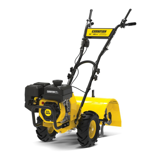
- Page 15 KNOW yOUR TIlleR model no. | contact us: 1.866.523.5218 060-1300-6 TIlleR 1. Front Bumper 2. Wheels 3. Wheel Lock Pins 4. Tines 5. Tine Shield 6. Depth Regulator Lever 7. Reverse Lever 8. Forward Lever 9. Handlebars 10. Speed Control...
- Page 16 | contact us: 1.866.523.5218 060-1300-6 eNGINe 1. Muffler Protects the engine by filtering dust and debris from the 2. Air Filter intake. 3. Throttle 4. Choke Used to start the engine. 5. Fuel Valve Used to turn fuel supply on and off to engine.
- Page 17 | contact us: 1.866.523.5218 060-1300-6 PARTs INClUDeD Accessories: Engine Oil [16.9 fl. oz. (500 ml)] Oil Funnel TOOls INClUDeD TOOls NOT INClUDeD 8-10 Wrench Needle Nose Pliers (for cotter pins) 12-14 Wrench 13-16 Wrench Spark Plug Wrench (engine)
- Page 18 | contact us: 1.866.523.5218 | contact us: 1.866.523.5218 060-1300-6 060-1300-6 Your tiller requires some assembly. This unit ships from our factory without oil. It must be properly serviced with fuel and oil before operation. If you have any questions regarding the assembly of your tiller, call our Technical Support Team at 1.866.523.5218.
- Page 19 | contact us: 1.866.523.5218 060-1300-6 INsTAll THe WHeels 1. Remove the locking pins from the wheel hubs. 2. The tiller wheels are directional. For best performance install the wheels with the tire thread facing the direction as shown.
- Page 20 | contact us: 1.866.523.5218 060-1300-6 INsTAll THe TINe sHIelD 1. Remove the (4) M10×25 mm flange head bolts installed in the tine shield brackets above the transmission housing. 2. Place the tine shield on the bracket and secure with the bolts removed in step 1.
- Page 21 | contact us: 1.866.523.5218 060-1300-6 ATTACH UPPeR HANDle 1. Slide the upper handle down over the lower handle and align the holes. 2. Insert the (4) M8×50 curved head bolts into the holes as shown and securely with the (4) handle knobs and (4) flat washers.
- Page 22 | contact us: 1.866.523.5218 060-1300-6 ATTACH sPeeD CONTROl 1. Attach speed control using provided (1) M6 bolt, (1) washer, and (1) M6 nut. 2. Tighten completely. 3. Use plastic clips to secure the cables as shown.
- Page 23 | contact us: 1.866.523.5218 060-1300-6 ATTACH fRONT bUMPeR 1. Slide the front bumper onto the outside of the base frame and align the holes. 2. Install the (4) M8×25 mm bolts and (4) M8 lock nuts and tighten securely.
- Page 24 | contact us: 1.866.523.5218 060-1300-6 INTRODUCTION This section describes the location and function of the controls on your tiller. Refer to the following section, Operation, for detailed operating instructions. Practice using these controls, with the engine shut off, until you understand the operation of the controls and feel confident with each of them.
- Page 25 | contact us: 1.866.523.5218 060-1300-6 FOR WHEEL DRIVE MODE: Slide wheel Wheel Drive Position outward and align the holes. Insert locking pin through wheel hub and wheel shaft. Secure wheel locking pin by pushing in as far as it will go then wrapping ring around the wheel shaft as shown.
- Page 26 | contact us: 1.866.523.5218 060-1300-6 fORWARD leVeR The Forward Lever controls the engagement of forward drive to the wheels and counter-rotating tilling with the tines. To operate the Forward Lever: 1. Put wheels in WHEEL DRIVE position (see “WARNING” statement).
- Page 27 | contact us: 1.866.523.5218 060-1300-6 DePTH ReGUlATOR leVeR ADJUsTMeNT This regulator lever controls the tilling depth of the tines. Remove pin and clip and slide regulator lever up or down as required. Reassemble pin and clip. The “travel position” (highest hole) raises the tines approximately 11⁄2" off the ground, allowing the tiller to be moved without the tines contacting the ground.
- Page 28 | contact us: 1.866.523.5218 | contact us: 1.866.523.5218 060-1300-6 060-1300-6 HANDlebAR HeIGHT ADJUsTMeNT The handlebar height is adjustable to three different settings. In general, adjust the handlebars so they are at waist level when the tines are 3 to 4" (8 to 10 cm) in the soil.
- Page 29 OPeRATION model no. | contact us: 1.866.523.5218 060-1300-6 INTRODUCTION Read this section before you start the engine. Then, take the time to familiarize yourself with the basic operation of the tiller before using it in the garden. Find an open, level area and practice using the tiller controls without the tines engaging the soil (put tines in “travel”...
- Page 30 | contact us: 1.866.523.5218 060-1300-6 CAUTION: Use regular unleaded gasoline with a minimum octane rating of 85 and an ethanol content of 10% or less by volume. DO NOT mix oil and gasoline. Fill tank to approximately ¼" (6.4 mm) below the top of the tank to allow for gasoline expansion.
- Page 31 | contact us: 1.866.523.5218 060-1300-6 ADD eNGINe OIl 1. Place tiller on a flat, level surface. 2. Put the wheels in the WHEEL DRIVE position. 3. Remove oil fill cap/dipstick to add engine oil. 4. Using a funnel, add up to 16.9 fl. oz. (500 ml) of oil and replace oil fill cap/dipstick.
- Page 32 | contact us: 1.866.523.5218 060-1300-6 sTARTING THe eNGINe To help prevent serious personal injury or damage to equipment: 1. Make certain the tiller is on a flat, level surface. 2. Put the wheels in the WHEEL DRIVE position (wheel pins must be through holes in wheel hubs and wheel shaft).
- Page 33 | contact us: 1.866.523.5218 060-1300-6 5. Move the choke lever to the “Choke” position. 6. Move the throttle lever to the “Fast” position. FAST SLOW 7. Move the fuel valve to the “ON” CHOKE position. FUEL OFF FUEL ON 8.
- Page 34 To alleviate high altitude issues other than the natural power loss, a high altitude carburetor main jet and installation instructions can be obtained by contacting Yardworks Canada 1.866.523.5218. The part number and recommended minimum altitude for the application of the high altitude carburetor main jet is listed in the table below.
- Page 35 | contact us: 1.866.523.5218 060-1300-6 sTOPPING THe eNGINe AND THe TIlleR In an emergency, turn the engine switch to the “Off” position. Under normal operation: 1. To stop the wheels and tines, release all control levers. 2. Turn the fuel valve to the “OFF” position.
- Page 36 | contact us: 1.866.523.5218 | contact us: 1.866.523.5218 060-1300-6 060-1300-6 TIllING DePTHs Avoid pushing down on the handlebars in an attempt to force the tiller to dig deeper. Doing so takes the weight off the powered wheels, causing them to lose traction. Without the wheels helping to hold the tiller back, the tines will attempt to propel the tiller –...
- Page 37 | contact us: 1.866.523.5218 060-1300-6 leT THe TIlleR DO THe WORK While tilling, relax and let the wheels pull the tiller along while the tines do the digging. Walk on the side that is not yet finished (to avoid making footprints in the freshly tilled soil) and lightly, but securely grip the handlebar with just one hand.
- Page 38 | contact us: 1.866.523.5218 060-1300-6 TIllING ON slOPes Read the following recommendations before tilling on slopes: If you must garden on a moderate slope, please follow two very important guidelines: 1. Till only on moderate slopes, never on steep ground where footing is difficult.
- Page 39 | contact us: 1.866.523.5218 060-1300-6 Terrace Gardening When a slope is too steep or too short for vertical tilling, it may be necessary to till – across the slope and create terraced rows. Terraces are rows that are cut into the side of a slope, creating a narrow, but flat area on which to plant.
- Page 40 | contact us: 1.866.523.5218 060-1300-6 CleARING THe TINes The tines have a self-clearing action which eliminates most tangling of debris in the tines. However, occasionally dry grass, stringy stalks or tough vines may become tangled. Follow these procedures to help avoid tangling and to clean the tines, if necessary.
- Page 41 | contact us: 1.866.523.5218 060-1300-6 lOADING AND UNlOADING THe TIlleR Before loading or unloading, stop the engine, wait for all parts to stop moving, – disconnect the spark plug wire and let the engine and muffler cool. The tiller is too heavy and bulky to lift safely by one person. Two or more people should –...
- Page 42 | contact us: 1.866.523.5218 | contact us: 1.866.523.5218 060-1300-6 060-1300-6 before each Use every 3 Months or every 50 Hours of Operation Check motor oil level Change engine oil Clean engine Replace reduction gear oil Check air filter element...
- Page 43 | contact us: 1.866.523.5218 060-1300-6 TIlleR lUbRICATION After every 10 operating hours, oil or grease the lubrication points as described below. – Use clean lubricating oil (#30 weight engine oil is suitable) and clean general purpose – grease (grease containing a metal lubricant is preferred, if available).
- Page 44 | contact us: 1.866.523.5218 060-1300-6 CHeCK HARDWARe Check for loose or missing hardware after every 10 operating hours and tighten or – replace (as needed) before reusing tiller. Be sure to check the screws underneath the tiller hood that secure the transmission –...
- Page 45 | contact us: 1.866.523.5218 060-1300-6 5. If the gear oil level is low, add GL-4 gear oil (SAE 85W-140 or SAE 140). 6. If the gear oil level is okay, securely replace the oil fill plug. IMPORTANT: Do not operate the tiller if the gear oil level is low. Doing so will result in severe damage to the transmission components.
- Page 46 | contact us: 1.866.523.5218 060-1300-6 TINes The tines will wear with use and should be inspected at the beginning of each tilling season and after every 30 operating hours. The tines can be replaced either individually or as a complete set.
- Page 47 | contact us: 1.866.523.5218 060-1300-6 C. Removing/Installing a Tine Assembly: 1. A tine assembly consists of eight tines mounted on a tine holder. 2. If removing both tine assemblies, mark them “left” and “right” before removal. Remove (2) pins and (2) cotter pins that secure the tine assembly to the tine shaft.
- Page 48 | contact us: 1.866.523.5218 060-1300-6 CHeCKING AND ADJUsTING fORWARD DRIVe belT TeNsION It is important to maintain correct tension on the forward drive belt. A loose belt will cause the tines and wheels to slow down — or stop completely — even though the engine is running at full speed.
- Page 49 | contact us: 1.866.523.5218 060-1300-6 5. To adjust the length of the spring: 5a. Release the forward lever. 5b. Un-thread the hex nut halfway up the adjustment screw. 5c. Unhook the top of the spring from the lever.
- Page 50 | contact us: 1.866.523.5218 060-1300-6 belT TeNsION ADJUsTMeNT Proper belt tension is critical to good performance. After 1/2 hour of operation, all cables may have to be adjusted due to initial stretch. Thereafter, check tension after every 2 hours of operation.
- Page 51 | contact us: 1.866.523.5218 060-1300-6 CHANGe fORWARD/ReVeRse belTs 1. Turn off engine. Engine must cool completely before proceeding. 2. Remove spark plug wire and secure away from spark plug. 3. Reduce the belt tension by loosening the forward and reverse cable lower jam nut.
- Page 52 | contact us: 1.866.523.5218 060-1300-6 6. To remove the forward drive belt: Forward Stud Assembly 6a. Remove the two forward belt guide studs and forward belt idler assembly. Forward Belt Idler 6b. Slide the belt free of the engine pulley.
- Page 53 | contact us: 1.866.523.5218 060-1300-6 7. To install the reverse drive belt: 7a. Insert the belt from underneath the unit and up around the reverse Reverse Belt Idler belt idler. 7b. Place the lower loop of the belt...
- Page 54 | contact us: 1.866.523.5218 060-1300-6 8. To install the forward drive belt: 8a. Insert the belt from underneath the unit and up around the rearward portion on the engine pulley. 8b. Place the lower loop of the belt around the rearward portion of the transmission pulley.
- Page 55 | contact us: 1.866.523.5218 060-1300-6 9. Tighten the forward and reverse lower jam nut. 10. Check the belt tension. The belts should be loose with the drive levers disengaged. 11. Replace the upper and lower belt guards. 12. Re-attach the spark plug wire to the spark plug.
- Page 56 | contact us: 1.866.523.5218 060-1300-6 eNGINe CleANING Keeping the engine clean will help to ensure smooth operation and prevent damage from overheating. Refer to the Engine Owner’s Manual for engine cleaning service intervals and instructions. Be sure that the muffler is cool before servicing the engine.
- Page 57 | contact us: 1.866.523.5218 060-1300-6 B. To Change the Engine Oil: 1. Place tiller on a flat, level surface. 2. Put the wheels in the WHEEL DRIVE position. 3. Remove the left-side wheel and carefully prop up until ready to drain the engine oil.
- Page 58 | contact us: 1.866.523.5218 060-1300-6 NOTICe: We consider the first 5 hours of run time to be the break-in period for the engine. During the break in period we recommend using standard automotive non-synthetic blended oils. After the break in period synthetic oil can be used but is not required.
- Page 59 | contact us: 1.866.523.5218 060-1300-6 AIR CleANeR MAINTeNANCe A dirty air cleaner can restrict air flowing into the carburetor. To keep the carburetor in good working conditions, please service the air cleaner periodically. If operating the engine in extremely dusty area, servicing should be done more often.
- Page 60 | contact us: 1.866.523.5218 | contact us: 1.866.523.5218 060-1300-6 060-1300-6 5. Measure the spark plug clearance with a spark plug gap gauge. The clearance should be 0.7-0.8 mm. If adjustment is necessary, bend the side electrode carefully.
- Page 61 | contact us: 1.866.523.5218 060-1300-6 Transport with the fuel valve turned the “OFF” position. Transport or store the engine when it is cool to avoid getting burns or starting a fire. Off-seAsON sTORAGe When the tiller won’t be used for an extended period, prepare it for storage as follows: 1.
- Page 62 | contact us: 1.866.523.5218 060-1300-6 ReMOVING fROM sTORAGe 1 Month No repair needed. 1-2 Months Drain the used gasoline and add fresh gasoline. 2 Months to a year Drain the used gasoline and add fresh gasoline. Drain the gasoline out of the carburetor cup.
- Page 63 | contact us: 1.866.523.5218 060-1300-6 PAGe INTeNTIONAlly lefT blANK.
- Page 64 VIeW (PRODUCT) model no. model no. | contact us: 1.866.523.5218 | contact us: 1.866.523.5218 060-1300-6 060-1300-6...
- Page 65 | contact us: 1.866.523.5218 060-1300-6...
- Page 66 | contact us: 1.866.523.5218 060-1300-6...
- Page 67 | contact us: 1.866.523.5218 060-1300-6...
- Page 68 PARTs lIsT (PRODUCT) model no. model no. | contact us: 1.866.523.5218 | contact us: 1.866.523.5218 060-1300-6 060-1300-6 Item Description Drawing qTy. Handle Bar Knob Nut 100380-001 Fan-shaped Screw M8 x 50 100380-002 Flange Bolt M6 x 35 100379-026 Handle Bar Assembly, Black 100380-003.2...
- Page 69 | contact us: 1.866.523.5218 060-1300-6 Item Description Drawing qTy. Spring Washer Ø8 100379-029 Bolt 5/16, 1"-24 100379-076 Gasoline Engine R210P-E00U Bolt M10 x 50 100380-024 Flat Washer Ø10 100379-040 Pin Ø1.5 x 20 100380-025 Cable Clip 100380-026 Pin Roll Ø6 x 16...
- Page 70 | contact us: 1.866.523.5218 060-1300-6 Item Description Drawing qTy. Spring 100380-045 Bolt M8 x 30 100380-046 Bumper, Black 100380-047.2 Circlip 10 100380-048 Circlip 8 100379-064 Circlip 24 100379-065 Locknut M8 100379-015 Forward Tension Wheel 100380-049 Clutch Arm Assembly...
- Page 71 | contact us: 1.866.523.5218 060-1300-6 Item Description Drawing qTy. Pin Roll Ø10 x 25 100380-067 Bolt M10 x 1 x 25 100379-113 Left Tillage Blade, Black 100380-068.2 Nut M10 x 1 100379-110 Tool Carrier Assembly, Black 100380-069.2 Pin Roll Ø10 x 42 100380-070 Pin Ø3 x 30...
- Page 72 | contact us: 1.866.523.5218 | contact us: 1.866.523.5218 060-1300-6 060-1300-6 Item Description Drawing qTy. Semicircle Key 100380-099 Tiller Worm Wheel 100380-100 Worm Wheel 100380-101 Worm Wheel Shaft 100380-102 Rear Cap, Black 100380-103.2 Screw M6 x 25...
- Page 73 | contact us: 1.866.523.5218 060-1300-6 PAGe INTeNTIONAlly lefT blANK.
- Page 74 VIeW (eNGINe) model no. model no. | contact us: 1.866.523.5218 | contact us: 1.866.523.5218 060-1300-6 060-1300-6...
- Page 75 PARTs lIsT (eNGINe) model no. | contact us: 1.866.523.5218 060-1300-6 Item Description Drawing qTy. Hexagon Flange Bolt, M6 x 12, Blue White Zinc 90001-0612-01 Cylinder Head Cover Subassembly, Blue White 12410-Z440110-00A1 Zinc Cylinder Head Cover Gasket 12004-Z440110-00A0 Tube, Breather, Ø8 x Ø12 x 90...
- Page 76 | contact us: 1.866.523.5218 060-1300-6 Item Description Drawing qTy. Oil Seal, Ø25 x Ø41.25 x 6 90682-Z300110-0001 Washer, Ø10 x Ø15.8 x 1.5 90408-Z010110-0000 Drain Plug Bolt, M10 x1.25 x15, Blue White Zinc 11007-Z010110-0000 Governor Gear Assembly 16400-Z010110-0000...
- Page 77 | contact us: 1.866.523.5218 060-1300-6 Item Description Drawing qTy. Flywheel Nut, M14 x 1.5, Blue White Zinc 13501-Z010110-0000 Ignition Coil 30400-Z441010-0101 Hexagon Flange Bolt, M6 x 25, Blue White Zinc 90001-0625-01 Cylinder Body Shroud, Blue White Zinc 19304-Z010610-0000...
- Page 78 | contact us: 1.866.523.5218 | contact us: 1.866.523.5218 060-1300-6 060-1300-6 Item Description Drawing qTy. Main Jet, Standard 16161-Z151710-0000 Main Jet, Altitude 3000-6000 Feet 16161-Z151510-0000 Main Jet, Altitude 6000-8000 Feet 16161-Z151310-0000 Seal Ring, Float 16112-Z010110-0000 Seal Ring...
- Page 79 | contact us: 1.866.523.5218 060-1300-6 PRObleM POssIble CAUse sOlUTION Spark plug wire disconnected. Reconnect wire. Engine Throttle Control Lever incorrectly Put lever in START position. set. Fuel tank empty. Add fuel. Choke control (if so equipped) in incorrect Move to CHOKE position.
- Page 80 | contact us: 1.866.523.5218 060-1300-6 PRObleM POssIble CAUse sOlUTION Tine holder mounting hardware missing. Replace hardware. Wheels turn, but Bolt loose in transmission pulley. Tighten bolt. tines don’t Internal transmission wear or damage. Contact Technical Support Team. Worn tines.
- Page 81 | contact us: 1.866.523.5218 060-1300-6 PRObleM POssIble CAUse sOlUTION Too much carbon deposit and dirt around Clear carbon deposits. electrodes. Too much carbon deposit and dirt around No spark Replace spark plug. electrodes. Too much carbon deposit and dirt around Adjust to proper value.
- Page 82 | contact us: 1.866.523.5218 060-1300-6 GAsOlINe eNGINe: NO POWeR PRObleM POssIble CAUse sOlUTION Air in fuel line or fuel line clogged. Exhaust air or dredge fuel line. Main oil flow hole is not adjusted properly. Readjust. In carburetor, needle valve hole and main Clean and blow to clear.
- Page 83 | contact us: 1.866.523.5218 060-1300-6 GAsOlINe eNGINe RUNNING ROUGHly PRObleM POssIble CAUse sOlUTION Piston, cylinder or piston ring is worn Replace the worn part. excessively. Piston pin and piston pin hole are worn Replace piston or piston pin.
- Page 84 | contact us: 1.866.523.5218 060-1300-6 sTOPs sUDDeNly WHeN RUNNING PRObleM POssIble CAUse sOlUTION Fuel is empty. Refill fuel. Carburetor is clogged. Check fuel line and dredge. Float is leaking. Repair. Dismantle float chamber and Needle valve is stuck.
- Page 85 | contact us: 1.866.523.5218 060-1300-6 eNGINe Is OVeRHeATING PRObleM POssIble CAUse sOlUTION Oil level is low. Fill oil to proper level. Exhaust pipe blocked up. Clean exhaust pipe. Shroud leaking. Repair damaged part. Cooling fins blocked by foreign matter.
- Page 86 060-1300-6 2-yeAR lIMITeD WARRANTy For TWO YEARS from the date of purchase within Canada, YARDWORKS CANADA will, at its option, repair or replace for the original purchaser, free of charge, any part or parts found to be defective in material or workmanship.
Need help?
Do you have a question about the 060-1300-6 and is the answer not in the manual?
Questions and answers