
Related Manuals for Yardworks 60-3815-0


Summary of Contents for Yardworks 60-3815-0
- Page 1 24 V Cordless Tiller/Edger 60-3815-0 Owner's Manual TOLL-FREE HELPLINE: 1 866 523-5218 WARNING Read all safety rules and operating instructions carefully before using this product.
-
Page 2: Table Of Contents
Edging Tine Depth..............................2" (5 cm) Wheel Type......................... 7" (17.8 cm) Radial, Ball bearing Weight with battery............................57 lbs (25.9 kg) Weight without battery............................41 lbs (18.6 kg) Run time............................Approximately 25 minutes CSA ..................................218549 Replacement battery: YardWorks 24 V Battery (60-2152-2) -
Page 3: General Safety Rules
GENERAL SAFETY RULES Secure long hair so that it is above shoulder level, in WARNING: order to prevent it from getting caught in moving parts. READ AND UNDERSTAND ALL INSTRUCTIONS Do not operate the tiller while under the influence of ... -
Page 4: Specific Safety Rules
SPECIFIC SAFETY RULES When starting the tiller, follow the instructions carefully, Do not overload the capacity of the tiller by cultivating too take up a normal operating position, and keep all body deep in a single pass or at too fast a speed. parts well away from the tines. -
Page 5: Symbols
SYMBOLS Some of the following symbols may appear on this tool. Study them carefully and learn their meaning. Proper interpretation of these symbols will allow for better and safer operation of the tool. SYMBOL NAME DESIGNATION/EXPLANATION Volts Voltage Amperes Current Hertz Frequency (cycles per second) Watts... - Page 6 SYMBOLS The following signal words and meanings are intended to explain the levels of risk associated with this product. SYMBOL SIGNAL MEANING DANGER: Indicates an imminently hazardous situation that can result in death or serious injury if it is not avoided. WARNING: Indicates a potentially hazardous situation that may result in death or serious injury if it is not avoided.
-
Page 7: Battery & Charger
BATTERY & CHARGER CHARGING PROCEDURE (Fig.1) The battery that is supplied with the tiller is a maintenance- free, sealed, 24 V storage battery. It can be tipped without danger of acid spillage. The charger will require BCI Switch approximately 10 hours to recharge a fully discharged Charger connector battery. -
Page 8: Features
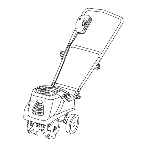
FE ATURES DIAGRAM OF THE TILLER See Figure 3. Safety key Power switch assembly Upper handle Charger 10 Ah 24 V battery Middle handle FIXED KNOB Lower handle BATTERY CLIP Edging blade TINE SHIELD 2 tubes 7" (17.8 cm) RADIAL TIRES 2 Eging wheels 2 hitch pins Gear box... -
Page 9: Assembly
ASSEMBLY UNPACKING WARNING: This product requires assembly. If any parts are missing, do not operate this tool Carefully remove the tool and any accessories from until the missing parts have been replaced. Failure the box. Verify that all of the items that are listed in to heed this warning could result in serious the packing list are included. -
Page 10: Safety Key
ASSEMBLY POSITIONING THE HANDLEBAR See Figure 5. 1. Align the holes on the middle handle with the holes on the lower handle. Insert the bolts, and tighten them using the wing nuts provided. 2. Align the holes on the upper handle with the holes on the middle handle. Insert the bolts, and tighten them using the wing nuts provided. - Page 11 ASSEMBLY INSTALLING THE TINES See Figure 6.1-6.4 The tiller comes with four tines. In order for the tiller to work properly, the tines must be installed in the correct order. The tiller can be used with four tines or two tines. Disconnect the battery from the tiller.
- Page 12 ASSEMBLY TINES INSTALLED CORRECTLY See Fig. 7. TINES INSTALLED CORRECTLY FRONT FLUTE FLUTE Fig. GEAR BOX INSTALLING TWO TINES FOR TILLING A NARROW AREA FRONT FLUTE HITCH PIN Fig. 8 Place tine (1) onto the shaft, and place tine (4) onto the shaft on the other side. Insert the hitch pin into the holes in order to secure the tines to the tine shaft.
-
Page 13: Assembly
ASSEMBLY INSTALLING THE EDGING BLADE See Figure 9.1-9.2 1. Place the left edging wheel (2) onto the shaft, and then place the edging blade (3) onto the shaft, with the flute of the blade facing in toward the gear box. Insert the hitch pin into the holes in order to secure the blade to the shaft. 2. -
Page 14: Operation
1 green lights The battery is at 60% capacity Amber light The battery is at 40% capacity, and requires charging soon Red light The battery is at 20% capacity, and requires charging immediately USE ONLY A YARDWORKS REPLACEMENT BATTERY (60-2152-2). - Page 15 OPERATION STARTING THE MOWER SAFETY KEY: Storage Operating In order to prevent accidental start-up or unauthorized use of the battery-operated tiller, a removable safety key has been incorporated into the design of the tiller. The tiller is completely disabled when the safety key is removed from the tiller Safety key NOTE: THE SAFETY KEY HAS A HOLE THROUGH THE...
- Page 16 OPERA TION PREPARING THE SEED BED WARNING: The tiller can be used to break up garden soil and to prepare a seed bed for planting. Plan ahead in order to leave enough Do not allow familiarity with power tools to make you room between the seed rows to allow for cultivating after the careless.
-
Page 17: Operation
OPERATION GENERAL CULTIVATING EDGING FEATURE See Figure 10. See Figure 11. Shallow cultivating (less than 2" (5 cm) deep) can be used This tiller is equipped with an edging feature. to disrupt weeds and aerate the soil without injuring nearby Remove the tines. - Page 18 ADJUSTMENTS WARNING: In order to prevent accidental starting, which could cause serious personal injury, disconnect the battery from the tiller before making any adjustments. ADJUSTING THE WHEEL ASSEMBLY POSITION SUPPORT See Figure 12. ROD(3) The drag bar can be used to help control the speed of the tiller and the depth of cultivation.
-
Page 19: Maintenance
MAINTENANCE Only the parts that are shown on the parts list are intended WARNING: to be repaired or replaced by the user. All other parts should be replaced at an Authorized Service Center Use only identical replacement parts when servicing the Maintenance Tips: tiller. -
Page 20: Warranty
WARRANTY For TWO YEARS from the date of purchase within Canada, YARDWORKS CANADA will, at its option, repair or replace for the original purchaser, free or charge, any part or parts found to be defective in material or workmanship. This warranty does not cover: 1. -
Page 21: Parts List
PARTS BREAKDOWN... - Page 22 PARTS BREAKDOWN Model No. Description Parts No. 925017 battery assembly battery holder 3411288 battery holder knob 3411188 925015 battery clip 925016 switch assembly 3490137 rubber soft-grip handle 3420189 upper-handle bolt M8*42 3220436 3410835 knob of handle 3320289 mid-handle 3410588 battery connector electrode 3220511 self-tapping screw ST4*12-C 3320589...
Need help?
Do you have a question about the 60-3815-0 and is the answer not in the manual?
Questions and answers