
Related Manuals for Yardworks 060-3801-2


Summary of Contents for Yardworks 060-3801-2
- Page 1 Electric Tiller/Cultivator 060-3801-2 218549 Owner's Manual TOLL FREE HELPLINE: 1-866-523-5218 IMPORTANT: Read and follow all safety rules and operating instructions before using this product.
-
Page 3: General Safety Rules
General Safety Rules WARNING: READ AND UNDERSTAND ALL INSTRUCTIONS. Failure to follow all instructions listed below may result in electric shock, fire, and/or serious personal injury. READ THESE INSTRUCTIONS CAREFULLLY • Read the Owner’s manual carefully. Become thoroughly familiar with the controls and the proper use of the equipment. - Page 4 General Safety Rules • Unplug the tiller and verify that all moving parts have come to a complete stop before cleaning, repairing, or inspecting the tool. • Never spray water directly into the motor compartment • Service on the tiller must be performed by qualified repair personnel only. Service or mainte- nance that is performed by unqualified personnel could result in injury to the user or damage to the product.
-
Page 5: Specific Safety Rules
Specific Safety Rules • Do not use the tiller near underground electric cables, telephone lines, pipes, or hoses. When in doubt, contact your utility company or telephone company in order to locate underground services. • Verify that your extension cord is in good condition. When using an extension cord, be sure to use one that is heavy enough to carry the current that your product will draw. - Page 6 Read Instructions Always wear safety headphone when operating Ear Protection this product.
- Page 7 Symbols The following signal words and meanings are intended to explain the levels of risk associated with this product. SYMBOL SIGNAL MEANING Indicates an imminently hazardous situation that can DANGER: result in death or serious injury if it is not avoided. Indicates a potentially hazardous situation that may WARNING: result in death orserious injury if it is not avoided.
- Page 9 Electrical **Ampere rating (on tool data plate) 0/2.0 2.1/3.4 3.5/5.0 5.1/7.0 7.1/12.0 12.1/16.0 Cord Length Wire Size (A.W.G.) 25´ 50´ 100´ — **Used on 12 gauge / 20 A circuit. NOTE: AWG = American Wire Gauge WARNING: Keep the extension cord away from the working area. Position the cord so that it will not get caught on lumber, tools, or other obstructions while you are working with a power tool.
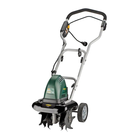
- Page 10 Features LOCATION OF PARTS (Fig. 1) HANDLEBAR SAFETY LOCK-OUT BUTTON PLUG CONNECTOR CIRCUIT BREAKER BALE TRIGGER CORD RETAINER TINE SHIELD WHEEL ASSEMBLY HITCH PIN INNER TINE OUTER TINE Fig. 1 Read this operator's manual and safety rules before operating your cultivator. Compare the illustration in Fig.1 to your cultivator in order to familiarize yourself with the location of various controls and adjustments.
-
Page 11: Packing List
Assembly UNPACKING This product requires assembly. • Carefully remove the tiller and any accessories from the box. Verify that all of the items that are listed in the packing list are included. • Inspect the tool carefully to verify no breakage or damage occurred during shipping. •... - Page 12 Assembly ASSEMBLING THE HANDLEBAR (Fig. 2) 1. Align the holes on the middle with the holes on the lower handles. Insert the bolts, and tighten them using the wing nuts provided. 2. Align the holes on the upper handle with the holes on the middle handle. Insert the bolts, and tighten them using the wing nuts provided.
- Page 13 Assembly ASSEMBLING THE WHEELS (Fig. 3-4) The wheels are used to control the depth of operation. To adjust the height of the wheels. 1. Disconnect from power source. 2. Place tiller in a stable position as shown in Fig. 3) 3.
- Page 14 Assembly INSTALLING THE TINES (Fig. 5.1-5.6) The tiller comes with four tines — For correct operation of the unit, the tines must be installed in the correct order. The tiller may be used with four tines or two tines. • Disconnect from power source. •...
- Page 15 Assembly INSTALLING THE TINES (Fig. 5.1-5.6) The tiller comes with four tines — For correct operation of the unit, the tines must be installed in the correct order. The tiller may be used with four tines or two tines. • Disconnect from power source. •...
- Page 16 Assembly TINES INSTALLED CORRECTLY (Fig. 7) NOTE: When the tines are installed correctly, the flute on the tines should line-up, and the angled edge of the tine blades should point towards the ground (Fig. 7). NOTE: The tiller will not operate properly if the tines are not installed correctly. If there is a problem with the cultivating operation of the tiller, check the tines for proper positioning.
-
Page 17: Operation
Operation WARNING: Do not allow familiarity with power tools to make you careless. Remember that a fraction of a second of carelessness is enough to cause a serious injury. WARNING: Always wear safety goggles or safety glasses with side shields when operating tools. - Page 18 Operation PREPARING THE SEED BED The tiller can be used to break up garden soil and prepare a seed bed for planting. Map out area to be tilled by planning ahead in order to leave enough room between the seed rows to allow for cultivating after the plants have grown.
-
Page 19: General Maintenance
Maintenance WARNING: When servicing, use only identical replacement parts. Use of any other parts may create a hazard or cause product damage. WARNING: Always wear safety goggles or safety glasses with side shields during power tool operation or when blowing dust. If operation is dusty, also wear a dust mask. WARNING: Before inspecting, cleaning or servicing the machine, unplug the power cord and wait for all moving parts to stop. -
Page 20: Troubleshooting
Troubleshooting Solution Problem Cause 1. The power cord is not plugged 1. Plug in the power cord. The tiller does in or the connection is loose. 2. Check circuit breaker. not start. 2. The household circuit breaker 3. Check wiring connection inside has been tripped. -
Page 21: Warranty
WARRANTY For TWO YEARS from the date of purchase within Canada, YARDWORKS ® CANADA will, at its option, repair or replace for the original purchaser, free or charge, any part or parts that are found to be defective in material or workmanship. -
Page 22: Exploded View
EXPLODED VIEW... - Page 23 EXPLODED VIEW...
-
Page 24: Parts List
PARTS LIST ITEM # PART NO. DESCRIPTION Upper handle ass’y and Switch 31106281 3320543 34901282 Felts 34203229-2 7” Wheel ass’y (right) Cord retainer 3411135 Turn cap for switch handle 34108283 Bolt of handle shaft 3220436-3 33205281-1 Lower handle shaft 33206281-1 Middle handle shaft 34250100 Rubber shaft... - Page 25 PARTS LIST ITEM # PART NO. DESCRIPTION 34203229-1 34101466 51.1 33104281-1 Gear box connector 51.2 32204281 Bolt 51.3 32916131 Spring washer 51.4 32103281-1 Bearing 51.5 32903281 Washer Φ15 51.6 32102268 Bearing 6202-2RS 51.7 34901281 Washer Φ32.5*Φ15*16 Gear box housing 51.8 33105281-1 51.9 Bolt M5*8...
- Page 26 Motor 36101285...
Need help?
Do you have a question about the 060-3801-2 and is the answer not in the manual?
Questions and answers