Daikin intelligent touch Controller DCS601C51 Operation Manual
Hide thumbs
Also See for intelligent touch Controller DCS601C51:
- Operation manual (99 pages) ,
- Hardware manual (16 pages)
Table of Contents
Advertisement
Model
DCS601C51
¡Thank you for purchasing intelligent Touch Controller.
¡This operation manual contains notes for safe use of the
product.
For correct use, be sure to read this manual
carefully before use.
¡When you have read this manual, be sure to store it in a
place where the operator can conveniently refer to at
anytime.
In case of personnel change, be sure to give the manual
to the new operator.
Operation Manual
Before use
Operation
Maintenance
Use smart and save smart
Be sure to follow the instructions below
Part Names on the Monitoring
Screen and the Functions
Operation
Precautions
Maintenance
LCD Maintenance
When Leaving the Product
Turned OFF for a Long Time
Troubleshooting
For Your Information
Options
Specification
After-sales Service
1
3
4
5
7
9
13
15
26
32
96
97
97
98
106
107
108
Advertisement
Table of Contents

Related Manuals for Daikin intelligent touch Controller DCS601C51


Summary of Contents for Daikin intelligent touch Controller DCS601C51
-
Page 1: Table Of Contents
Operation Manual Before use Safety Precautions Be sure to follow the instructions below System Overview Features and Functions Part Names and Functions Part Names on the Monitoring Screen and the Functions List Icon Operation Operation Quick Reference Air Conditioner Operation Monitoring Operation of Air Conditioner System Setup Menu Maintenance... -
Page 2: Safety Precautions
Safety Precautions To gain full advantage of the air conditioner's functions and Contact professional personnel about attachment of to avoid malfunction due to mishandling, we recommend accessories and be sure to use only accessories that you read this instruction manual carefully before use. specified by the manufacturer. - Page 3 Do not remove the outdoor unit's fan guard. Do not let children play on or around the outdoor unit. The guard protects against the unit's high speed fan, If they touch the unit carelessly, injury may be caused. which may cause injury. Consult your dealer regarding cleaning the inside of Do not place objects that are susceptible to moisture the air conditioner.
-
Page 4: System Overview
System Overview This intelligent Touch Controller is capable of controlling / monitoring up to 64 groups of indoor units henceforth termed group(s) . Main functions of the intelligent Touch Controller : 1. Collective starting / stopping of operation of the indoor units connected to the intelligent Touch Controller. 2. -
Page 5: Features And Functions
Features and Functions I Operation Menu See pages The intelligent Touch Controller is capable of starting / stopping operation by the group or zone. Collective starting / stopping is also available. I Air Conditioner Detail Setup See pages Temperature setting, switching between temperature control modes, switching of speed and direction of airflow and remote control mode setting are available by the group, by the zone or collectively. -
Page 6: Part Names And Functions
Part Names and Functions Front and Side View PCMCIA Card Slot Color LCD with Touch Panel Touch Pen Used when using the optional Provides a display for monitoring Be sure to operate with the touch Power Proportional Distribution and operation. pen and take care not to lose it. - Page 7 Terminals on the Back of intelligent Touch Controller Terminal block for power supply Connect to AC100-240V power supply. RS232-C connector for Terminal size is M4. D#-NET Plus adapter Modem connector for AIRNET Using D#-NET Plus adapter When using AIRNET service, being sold as an accessory, connect it to the telephone line.
-
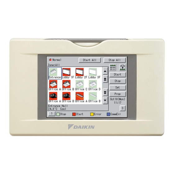
Page 8: List
Part Names on the Monitoring Screen and the Functions List Display Mode Selection Contents of the List Currently Displayed Zone / Group Currently Displayed ¡When Group List is displayed The name of the zone / group Press the button and display Zone : Zone Name currently selected is highlighted change between Zone and Group. - Page 9 List Display for Collective Monitoring of Air Conditioners Connected to intelligent Touch Controller Start All Button When operation is normal and any air conditioner is in operation : Button to collectively start all the Red / Normal air conditioners connected to When operation is normal and all air intelligent Touch Controller.
-
Page 10: Icon
Icon Contents of the List Currently Displayed Display Mode Selection Zone / Group Currently Displayed ¡The particular Zone being Select between Zone and Group. The name of the zone / group currently monitored appears here. selected is highlighted in blue flame. Zone : Zone Name ¡When Zone List is displayed System Condition Displayed Domain... - Page 11 Icon Display for Collective Monitoring of Air Conditioners Connected to intelligent Touch Controller Start All Button When operation is normal and any air conditioner is in operation : Button to collectively start all the Red / Normal air conditioners connected to When operation is normal and all air intelligent Touch Controller.
- Page 12 Icon Contents of the List Currently Displayed Zone / Group Currently Displayed Display Mode Selection ¡The particular Zone being The name of the zone / group currently Press the button ana display monitored appears here. selected is highlighted in blue frame. change between Zone and Group.
- Page 13 Icon Display for Collective Monitoring of Air Conditioners Connected to intelligent Touch Controller When operation is normal and any air Start All Button conditioner is in operation : Red / Normal Button to collectively start all the When operation is normal and all air air conditioners connected to conditioners are in stoppage : Green / Normal...
-
Page 14: Quick Reference
Quick Reference Air Conditioner Operation I To collectively start / stop the operation of all devices connected See page to the intelligent Touch Controller I To start / stop the operation of devices by group See page I To start / stop the operation of devices by zone See page I To change the operation mode See page... - Page 15 System Settings Menu I To change the name of a group See page I To change the zone settings See page I To change the schedule See pages I To change the Automatic Changeover See pages I To change the temperature limit See pages I To change the heating optimization settings See pages...
-
Page 16: Air Conditioner Operation
Air Conditioner Operation Starting / Stopping Operation Collectively To start / stop the operation Screen 1 Monitoring of all devices connected Start or stop collectively the operation of devices connected. On the Monitoring screen, operation is allowed with either Zone or Group as the display mode and with either Icon or List as the display type. - Page 17 Starting / Stopping Operation by the Group To start / stop the operation Screen 1 Monitoring of devices by group Start or stop the operation of air conditioners by group. The example on the left shows the screen for starting / stopping the operation of Group Name : 1F North registered for Zone Name : Canteen.
- Page 18 Starting / Stopping Operation by the Zone To start / stop the operation Screen 1 Monitoring of devices by group Start or stop by zone the operation of groups of air conditioners set in zones. The example on the left shows a screen for starting or stopping the operation of air conditioners in the canteen.
- Page 19 Switching the Operation Mode Switch the operation mode of the air Screen 1 Monitoring conditioner. On the Monitoring screen, operation is allowed with either Icon or List as the display type. The operation mode can be switched by zone or by group. Selecting a zone and switching the operation mode switches the mode of all air conditioners in the zone.
- Page 20 Changing the Temperature Setting Change the temperature setting of air conditioners. Screen 1 Monitoring On the Monitoring screen, operation is allowed with either Icon or List as the display type. The temperature setting can be switched by zone or by group. Selecting a zone and changing the temperature setting changes the setting of the air conditioner groups in each selected operation in the zone.
- Page 21 Resetting the Filter / Element Sign Screen 1 Monitoring Reset the filter or element sign after cleaning any air conditioner showing the filter or element sign. On the Monitoring screen, operation is allowed with either Icon or List as the display type.
- Page 22 Changing the Direction / Fan Speed Screen 1 Monitoring Change the air direction or volume of air conditioners. On the Monitoring screen, operation is allowed with either Icon or List as the display type. The air direction or volume can be changed by zone or by group.
- Page 23 Changing the Range of Operation Allowed with Remote Control Screen 1 Monitoring Change the setting of operation with the remote control of air conditioners between Permitted and Prohibited. On the Monitoring screen, operation is allowed with either Icon or List as the display type. The setting between Permitted and Prohibited can be changed by zone or by group.
- Page 24 Set Ventilation Mode Screen 1 Monitoring (Icon) Perform the following procedure to switch the ventilation mode: On the monitoring screen, you can select any of the following display types: Icon, Detailed Icon, or List. When changing the ventilation modes of all the ventilation groups of a zone, select the zone and switch the ventilation mode.
- Page 25 Set Ventilation Volume Screen 1 Monitoring Perform the following procedure to change the ventilation volume: On the monitoring screen, you can select any of the following display types: Icon, Detailed Icon, or List. When changing the ventilation volumes of all the ventilation groups of a zone, select the zone and switch the ventilation volume.
- Page 26 Permit / Inhibit setting of Ventilation Remote Control Operations Screen 1 Monitoring Perform the following procedure to enable or disable the ventilation remote control operations: On the monitoring screen, you can select any of the following display types: Icon, Detailed Icon, or List. You may enable or disable the remote control operations in units of zones or groups.
-
Page 27: Monitoring Operation Of Air Conditioner
Monitoring Operation of Air Conditioner Monitor Zone or Group Operation Status Screen 1 Monitoring (Icon Display) Monitor Zone or Group Operation Status On the monitoring screen, you can select any of the following display types: Icon, Detailed Icon, or List. Push the button w to select a display type. - Page 28 Monitor Zone or Group Operation Status Screen 4 Legend Description At o, you can monitor at a glance the operation status of all air conditioners connected to the Intelligent Touch Controller. When no problem is found and one or more air conditioners are operating : Display in red When no problem is found and air conditioners are not operating : Display in green...
- Page 29 Monitoring Detailed Information Monitor Operation Status of a Zone or Group in Detail Screen 1 Monitoring (Icon Display) When monitoring the operation status in detail, you may choose any of three display types, icon, detailed icon and list. You may monitor the details of the operation status in units of zones or groups.
- Page 30 Monitoring Detailed Information Screen 4 Monitoring Screen (Icon Display) Push [Details] button !7 . The following maintenance data is displayed on the Detailed Information Screen Screen 5. Note that screens in the left-hand column are examples for group selection. [For group selection] Name : Group name Detailed name : Detailed group name Type : ID-Unit / HRV / D3Dio / D3Di...
- Page 31 Monitoring Detailed Information Monitor Ventilation Status of a zone or group in Detail Screen 1 Monitoring (Icon) When monitoring the operation status in detail, you may choose any of three display types, icon, detailed icon and list. You may monitor the details of the operation status in units of zones or groups.
- Page 32 To set / release the lock of screen operation Screen 1 Monitoring (Icon) Lock and Unlock Operations on the Screen You may use a password to lock and unlock operations on the screen. To make this lock / unlock setting, you have to assign an unlock password on P57 beforehand.
-
Page 33: System Setup Menu
System Settings Menu The System Settings menu includes the following items: Automatic Control : System menu : ¡Schedule ¡Passwords ¡Automatic Changeover ¡Date / Time ¡Temperature Limit ¡Backlight ¡Heating Mode Optimization ¡Zone / Group ¡FC Change Over ¡Locale ¡Alarm E-mail ¡Network ¡Simple lnterlock ¡Web Server ¡Icon color... - Page 34 System Settings Operation Description Menu Item (Reference) See page A backlight is used for the LCD of the intelligent Touch Controller. The backlight Backlight has its service life and the luminance of the backlight is reduced in proportion to the period of time it is illuminated. This setting is for preventing the luminance from being reduced in a short time by automatically turning the backlight OFF when the touch panel has been left untouched for a set period of time.
- Page 35 System Settings Operation Description Menu Item (Reference) See page This menu permits you to select a language from the list displayed on the Locale Intelligent Touch Controller. By setting locale, you can display data in the selected language on the Intelligent Touch Controller.
- Page 36 System Settings Operation Description Menu Item (Reference) This menu permits you to make settings for the scheduled operations in units of zones or groups. Setting The scheduled operations are used to automatically start or stop an air Schedule conditioner at the date and time (year, month, day, day of the week, hour and minute) previously set in the Intelligent Touch Controller according to the Outline operating conditions of the air conditioner.
- Page 37 Operation System Settings Description (Reference) Menu Item 3. [Set events for zone 2F.] See pages Setting NOTE: The following lists the events for reference. Scheduled Change the settings according to the actual use conditions. Event Setting events for Monday to Friday Time Target zone Start/stop...
- Page 38 System Settings Operation Description Menu Item (Reference) See page This function allows the optimal room temperature to be maintained without the users Automatic having to change the operation mode by automatically switching the air conditioner’s Changeover operation mode (cooling or heating) according to the room temperature for locations where there are vast temperature differences between day and night.
- Page 39 System Settings Operation Description Menu Item (Reference) See page < Control Implementation Conditions > Automatic The relationship between the main room temperature, the main set temperature, Changeover and the operation mode is described below, with examples. (Two examples are given, as the operation differs for temperature differences 2°C and below and 3°C and above.) The controls are implemented when the control conditions are satisfied, every 5 minutes from the time the power is turned on.
- Page 40 System Settings Operation Description Menu Item (Reference) See page The control instruction is sent to the indoor units registered in the automatic cooling / Automatic heating switch group when the control implementation conditions shown on the Changeover previous page are fulfilled. The actual control instructions sent differ according to the control method setting (fixed air conditioner / operating air conditioner selection / average) and the fulfilled conditions such as to switch from cooling to heating.
- Page 41 System Settings Operation Description Menu Item (Reference) See page Automatic <Precautions when using this control> CAUTION : Do not use the set temperature restriction function in indoor units Changeover which are subject to control. If it is used, operation modes will be switched and the set temperature will be changed repeatedly, possibly causing the air conditioners to break down.
- Page 42 System Settings Operation Description Menu Item (Reference) See page Automatic 4.Because this control automatically switches the operation mode, if the air conditioner is not a cooling / heating free unit, always register indoor units which have Changeover the right to select cooling or heating for the same cooling system to the same automatic cooling / heating switch group, when controlling indoor units which do not have such rights.
- Page 43 System Settings Operation Description Menu Item (Reference) See page This function automatically starts and stops air conditioners in order to prevent the Temperature room temperature of unmanned rooms from getting too high or too low. For example, Limit This has the following advantages. ¡It prevents overheating of or condensation from forming on equipment which needs to be temperature controlled in unmanned rooms.
- Page 44 System Settings Operation Description Menu Item (Reference) See page e : Control Implementation Conditions Temperature The relationship between room temperature, upper / lower limit, and operation Limit mode is shown below. The controls are implemented when the control conditions are satisfied, every 5 minutes from the time the power is turned on.
- Page 45 System Settings Operation Description Menu Item (Reference) See page Temperature r : Precautions for the use of this control The operation modes are switched over automatically with this control. Therefore, if Limit the air conditioners are not cooling / heating-free machines, and when an indoor unit without cooling / heating selection right is to be controlled, be sure to register an indoor unit with cooling / heating selection right in the same cooling system into the same room temperature upper / lower limit group.
- Page 46 Description Menu Item (Reference) See page When operation in the heating mode, Daikin VRV systems continue Heating to circulate a small volume of refrigerant gas through indoor unit that Mode are in an acceptable condition (thermo-off). As the fan will continue...
- Page 47 System Settings Operation Description Menu Item (Reference) See page w : Control execution condition Heating The relationship between room temperature, set temperature, and operation / Mode stop status is shown in the figure below. Optimization The operation period of the control is every 5 minutes after the system power is turned on, and the operation is executed when the control conditions are met at each timing.
- Page 48 System Settings Operation Description Menu Item (Reference) See page FC Change Over combines the functions of Changeover and Free Cooling to maintain FC Change the room temperature within a comfortable range while consuming minimal energy Over through the use of outside air. A comfortable range is configurable. FC Change Over replaces Automatic Changeover, Heating Mode Optimization functions and Setpoint Range limitation in the Group Settings.
- Page 49 System Settings Operation Description Menu Item (Reference) See page [2] Sequence of Operation FC Change Over (1) Changeover The Controller compares the room temperature to the preset cooling and heating setpoints. It automatically switches operation modes and overrides the setpoint of all indoor units in the group when the room temperature is outside of the range of the preset temperatures.
- Page 50 System Settings Operation Description Menu Item (Reference) See page (2) Free Cooling FC Change For free cooling, the controller automatically controls the ventilation equipment. In this Over case the HRV unit is set at the bypass mode and/or an outside air damper is opened to intake outside air.
- Page 51 System Settings Operation Description Menu Item (Reference) See page FC Change The illustration below shows the sequence of operation for Free Cooling. Over Room Outside air temperature temperature Temperature Preset cooling setpoint (maximum temperature) – 4°C Minimum free +1°C cooling target temperature Preset heating setpoint (minimum temperature)
- Page 52 System Settings Operation Description Menu Item (Reference) See page FC Change [3] Control Group Register units in the zone as a control group, and FC Change Over provides the Over individual control for the zone. • Control group Outdoor unit Representative indoor indoor...
- Page 53 System Settings Operation Description Menu Item (Reference) See page [4] Notes FC Change Read the following instructions to properly use the FC Change Over function. Over (1) Control group setting and cooling-heating Changeover To ensure that the changeover functionality of the control can switch the operating mode of the system, be sure to register indoor units that are not changeover masters in a control group along with the one that is the changeover master in the system.
- Page 54 System Settings Operation Description Menu Item (Reference) See page FC Change (2) Control sequence when the representative indoor unit is in off With the FC Change Over function, control is conducted by the return air temperature of the Over representative indoor unit (fixed) as the room temperature. In order for I-TC to reference the return air temperature of the representative indoor unit, the representative unit must be operating.
- Page 55 Operation System Settings Description (Reference) Menu Item Alarm E-mail See pages This option is used to, when the Intelligent Touch Controller detects a malfunction in such as the air conditioning unit (*1), send an e-mail containing the date, the error * The e-mail code and so on to the pre-registered administrators at three different addresses function is...
- Page 56 Operation System Settings Description (Reference) Menu Item Timing of E-mail Sending Alarm E-mail See pages Referring to the figure below, timing of sending e-mails is described. * The e-mail [Send when a malfunction occurs in the normal state] function is If a malfunction occurs in the destination groups defined in the e-mail sending, wait included in three minutes from the malfunction (q in the figure below) before sending an e-mail.
- Page 57 From : iTouch@daikin.co.jp Originating e-mail address separately, To : user012@daikin.co.jp Destination e-mail address where Subject : Fault occurs (DAIKIN Head Office) Fixed string of characters combined and controller name with the Web 04/02 14:11 Office A9 Date of occurrence of the malfunction (month, day, function.
- Page 58 Operation System Settings Description (Reference) Menu Item Simple This menu is used to make settings of an interlock control function in units of zones or See pages groups. Interlock The simple interlock control is a function to automatically control groups or zones corresponding to a change of the operation states or the stop states in any groups.
- Page 59 Operation System Settings Description (Reference) Menu Item Control operations when a communication error occurs Simple See pages in the interlock input points Interlock Example 1) When a communication error occurs in any of the interlock input points, the condition will be checked only for the interlock input points in the normal communication state.
- Page 60 Operation System Settings Description (Reference) Menu Item Simple In the following section, utilization of the simple interlock control function is described See pages while giving some examples. Interlock Referring to the figure below, the setting examples of the simple interlock control program are provided.
- Page 61 Operation System Settings Description (Reference) Menu Item • Limitations of the simple interlock function Simple See pages In the simple interlock function, setting the inconsistent input/output conditions is Interlock allowed as described below. * Priority of the interlock programs is determined in such a way that the lower program has a higher priority and the output 2 has a higher priority than the output 1.
- Page 62 Operation System Settings Description (Reference) Menu Item Simple Interlock See page [Change the name of the simple interlock program] Change Name You can customize the name of the simple interlock program, such as the name that reflects its functionality. Simple Interlock See page [Determine the validity / invalidity of the simple interlock setting] Validity / Invalidity...
- Page 63 System Settings Operation Description Menu Item (Reference) This menu should be displayed on the screen stored in the memory of History See page intelligent Touch Controller and used to store data in the memory card, which is field supplied. See page Menu for adjusting the positions of buttons on the touch panel used as the Touch Panel screen of the intelligent Touch Controller.
- Page 64 System Settings Menu Operation Screen 1 Monitoring Screen Viewing the System Settings Menu Screen Press the [S] button q on Screen 1 Monitoring. Screen 2 System Settings Menu (see lower left) appears. If a password is set, the screen does not appear unless the password is entered.
- Page 65 System Settings Menu Operation Passwords Screen 1 Passwords Select Passwords at Screen 2(A) on page 63. Screen 1 Passwords, which is shown on the left, appears. Select Enabled or Disabled for password Protection q. If Disabled is selected, press the [Close] button w.
- Page 66 System Settings Menu Operation Data / Time Screen 1 Date / Time Select Date / Time at Screen2(A) on page 63. Screen 1 Deta / Time, which is shown on the left, appears. Press the [Modify] button q. Time setting dialog in Screen2 is displayed.
- Page 67 System Settings Menu Operation Backlight Screen 1 Backlight Select Backlight at Screen 2(A) on page 63. Screen 1 Backlight, which is shown on the left, appears. Press Enabled or Disabled for Backlight Auto Off q. If you select Disabled, go to step 6. CAUTION For longer service life of the backlight, select Enabled whenever the backlight does not need...
- Page 68 System Settings Menu Operation Screen 1 Zone/Group Group Settings Select Zone/Group at Screen 2(A) on page 63. Screen 1 Zone/Group, which is shown on the left, appears. Select the group to be set with q. Press the [Settings] button w. Group Settings in Screen 2 is displayed.
- Page 69 System Settings Menu Operation Screen 1 Zone/Group Zone Settings Select Zone Settings at Screen 2(A) on page 63. Screen 1 Zone/Group, which is shown on the left, appears. To add a zone, press the [Add] button q. A zone is added with the name Z- 000.
- Page 70 System Settings Menu Operation Zone Settings 2 Screen 3 Registered Groups Edit Set the groups to be registered for the zone currently selected. To add a group to the zone, select the group to be added with !7 and press the [<<] button !8 .
- Page 71 System Settings Menu Operation Screen 1 Network Network Select Network at Screen 2(A) on page Confirm that the Network screen Screen 1 will be displayed as shown in the left-hand column. Push the [Modify] button q and enter a Host name on the resulting input Push the [Modify] button w and enter an IP address on the resulting input screen.
- Page 72 System Settings Menu Operation Screen 1 Web Server Web Server Setting Web Server at Screen 2(A) on page 63. Screen 1 Web Server as shown on the left will be displayed. Set the desired port number. Select either Default q, or User settings w.
- Page 73 System Settings Menu Operation Screen 1 Icon color Icon Color Select Icon color at Screen 2(A) on page 63. Confirm that the Icon color screen Screen 1 will be displayed as shown in the left-hand column. Select a desired color via the radio button q to change the start/stop icon color on the Icon color screen.
- Page 74 System Settings Menu Operation Screen 1 Activation key input Activation Key Input Scroll the System Settings menu and select Activation key input at Screen 2(A) on page 63. Confirm that the Activation key input screen Screen 1 will be displayed as shown in the left-hand column.
- Page 75 System Settings Menu Operation Screen 1 Schedule Set Schedule and Calendar Before setting a calendar, refer to Page 35 to consider what kind of schedule to set, and to perform the operations. The following is an example for Zone 2, on Page This example shows the setting that determines which days in the year schedule to use for special days (such as the...
- Page 76 System Settings Menu Operation Screen 1 Schedule Set Schedule and Event Before setting a event, refer to Page 36 to consider what kind of schedule to set, and to perform the operations. The following is an example for Page 36. Select Schedule at Screen 2(B) on page Confirm that the Schedule Screen 1 will be displayed as shown in the left-hand...
- Page 77 System Settings Menu Operation Screen 3 Events A full description of each button has been given above. The following discusses how to make the actual settings. To define the new operation, push the [Add] button r. To change the previously set operation, push the [Modify] button y.
- Page 78 System Settings Menu Operation Screen 4 Advanced Settings Push the [Advanced settings] button !8 on the Events Screen 3 to display an Advanced Settings Screen 4. The current settings of events are shown at the left side of the buttons @1 to @4 . ¡Operation Mode : Refers to the operation mode for a zone or group.
- Page 79 System Settings Menu Operation Screen 1 Schedule Change Schedule Name Select Schedule at Screen 2(B) on page Confirm that the Schedule Screen 1 will be displayed as shown in the left-hand column. Select a schedule from the list q to change the name.
- Page 80 System Settings Menu Operation Convenient Function 1 Screen 1 Schedule Copy in Units of Events ∗ When it is necessary to reuse an event set for a day of the week, this function greatly helps you copy the event to the other day of the week.
- Page 81 System Settings Menu Operation Screen 1 Schedule Convenient Function 2 Copy or Delete in Units of Schedules ∗ When it is necessary to resume a calendar setting made for schedule 1, this function greatly helps you copy the calendar setting to the other schedule(s).
- Page 82 System Settings Menu Operation Operation of Automatic Changeover Screen 1 Automatic Changeover Before performing Automatic Changeover, thoroughly read the Automatic Changeover section on page 37, and perform the following procedures: See page 63 and select Automatic Changeover . Screen 1 Automatic Changeover, which is shown on the left, appears.
- Page 83 System Settings Menu Operation Operation of Temperature Limit Screen 1 Temperature Limit Before performing Temperature Limit, read thoroughly the section Temperature Limit on page 42, and perform the following procedure. See page 63 and select Temperature Limit . Screen 1 Temperature Limit, which is shown on the left, appears.
- Page 84 System Settings Menu Operation Operation of Heating Mode Optimization Screen 1 Heating Mode Optimization Before performing Heating Mode Optimization, thoroughly read the Heating Mode Optimization Settings section on page 45, and perform the following procedures: See page 63 and select Heating Mode Optimization. Screen 1 Heating Mode Optimization, which is shown on the left, appears.
- Page 85 System Settings Menu Operation Before use of the FC Change Over Outside air ! -TC thermometer NOTE 1) When FC Change Over function mode is selected, D#Ai Unit(DAM101A51) Address 1:4–15 (fixed) the number of groups of the indoor units intelligent Touch Controller is capable of controlling/monitoring becomes to 63 from 64.
- Page 86 System Settings Menu Operation Setting of the FC Change Over Screen 1 FC Change Over Read page 47 for the function of FC Change Over. This chapter explains how to make settings for FC Change Over. [Restrictions] - Use the Master ITC to make settings. (No setting is possible from the Slave ITC.) Select FC Change Over in the menu window shown in page 63 to show screen 1.
- Page 87 System Settings Menu Operation Screen 1 Confirm Setting of the FC Change Over When the control group selected in the FC Change Over screen is Enable, Screen 1 for confirmation is shown to confirm read-only mode. Press [Yes] button q to show the Control group setting screen in a read-only mode.
- Page 88 System Settings Menu Operation Setting of the FC Change Over Screen 1 Registration of Indoor Unit The Registered list q shows indoor units registered in a control group. The Unregistered list w shows indoor units not shown in the Registered list q. When adding an indoor unit to a control group, select a unit to add from the Unregistered list w and press [<<] button e.
- Page 89 System Settings Menu Operation Setting of the FC Change Over Screen 1 Ventilation Device registration Ventilation Device registered in a control group are shown in the Registered list q. Ventilation Device not shown in the Registered list q are shown in the Unregistered list w. When adding a Ventilation Device to a control group, select a Ventilation Device to add from the Unregistered list w and press [<<] button r.
- Page 90 System Settings Menu Operation Check for History Screen 1 History Select History at Screen 2(A) on page The History screen Screen 1 appears as shown in the left-hand column. When checking for the history of system settings operations, touch the [Operation history] button q to confirm that the Operation history screen Screen 2 is displayed.
- Page 91 System Settings Menu Operation Screen 1 Touch Panel Calibration Touch Panel Calibration See page 63 and select Touch Panel Calibration . Screen 1 Touch Panel Calibration, which is shown on the left, appears. Follow the instruction shown on the screen and press the intersection of the crosshairs q and keep it pressed for about 1 second.
- Page 92 System Settings Menu Operation Push the [Modify Password] button !0 . Screen 3 Alarm E-mail Configuration Enter the password that is used for authentication on the input screen. Enter the password if POP before SMTP or SMTP-AUTH is selected for the authentication method. Last, push the [OK] button !1 to return to the Alarm E-mail screen Screen 1.
- Page 93 System Settings Menu Operation Screen 1 Simple Interlock Simple interlock Following the steps on page 63, to select Simple Interlock . As shown in the figure of the Screen 1 on the left side, the interlock Setup setting screen will be displayed.
- Page 94 System Settings Menu Operation Screen 4 Advanced settings In the Screen 3 Events on the previous page, pressing the [Advanced settings] (See ) will display the Advanced settings screen shown in the Screen 4 on the left side. The information displayed in the boxes pointed by is the current settings of the event.
- Page 95 System Settings Menu Operation Screen 5 Simple Interlock Simple Interlock Change Name From the menu displayed on Page 63, select Simple Interlock . As shown in the figure of the Screen 5 on the left side, the simple interlock screen will be displayed. From q, select a simple interlock program of which you want change the name.
- Page 96 System Settings Menu Operation Screen 1 Version Information Version Information This is a menu for checking the version number of the software for the intelligent Touch Controller currently used. Generally it is not necessary to check. From Screen 2(A) displayed on Page 63, scroll the menu and select Version Information .
- Page 97 Precautions Internal Battery Enable (ON) / Disable (OFF) Switch The intelligent Touch Controller is equipped with internal batteries in order to run the clock during blackouts as well as to save data during blackouts when using the optional Power Proportional Distribution.
- Page 98 Maintenance LCD Maintenance ¡When the surface of the LCD or the main unit of the intelligent Touch Controller is soiled, wipe the soil off with a piece of cloth soaked in a diluted neutral detergent and wrung sufficiently. Note Do not use thinner, organic solvent, strongly acid solution, etc. The print may fade or wear out and discolor.
- Page 99 Troubleshooting Before Having the Product Serviced Item Description and Corrective Action When Backlight Auto OFF is set for Backlight of the intelligent The display of the intelligent Touch Controller, the light goes out if the screen is left Touch Controller has gone out. untouched for a certain time.
- Page 100 Before Having the Product Serviced Item Description and Corrective Action On the Monitoring screen, The intelligent Touch Controller is designed in such a way that buzzer sounds when an area the buzzer sounds when any part of the screen is pressed. It not allocated for a button for is normal.
- Page 101 Before Having the Product Serviced Item Description and Corrective Action Is the indication System Central controlled on the Monitoring Collective Operation, Start and screen, as shown below? Stop buttons are not shown on This indication is shown in the following cases. the Monitoring screen of the intelligent Touch Controller and When iPU, Interface for use in BACnet...
- Page 102 Before Having the Product Serviced Item Description and Corrective Action The followings are possible causes. Check the followings. The air conditioner is 1. Is the stop operation performed with the remote control of the supposed to operate, but it is air conditioner? stopped.
- Page 103 Before Having the Product Serviced Item Description and Corrective Action Is the indication System Forced Stop on the Monitoring screen, as Collective Operation, Start and shown below? Stop buttons are not shown on This indication is shown in the following cases. the Monitoring screen of the When forced stop command is input to central management intelligent Touch Controller and...
- Page 104 Before Having the Product Serviced Item Description and Corrective Action The air conditioning unit might be stopped by the simple The air conditioning unit does interlock control function. not operate. Check the settings of the simple interlock function. In the case described below, the air conditioning unit : 1-01 will not operate.
- Page 105 Emergency Procedure for intelligent Touch Controller Failure Item Description and Corrective Action Failure occurs in the intelligent As a temporary measure before our service personnel investigates into the problem, turn OFF the power supply Touch Controller while the breaker of the intelligent Touch Controller. This allows all remote control is disabled with kinds of operation with the remote control of air conditioners in the intelligent Touch Controller...
- Page 106 When it is desired to adjust screen brightness, contrast and buzzer sound level Item Description and Corrective Action Screen brightness, contrast The screen brightness, contrast and buzzer sound level are factory adjusted properly before shipment, but in case where and buzzer sound adjustment the screen is hard to see and the buzzer is hard to hear, for is desired.
- Page 107 Options Connecting Unification adaptor allows using the contact for normal and abnormal operation signal and collective start/stop with a contact. For details, contact the vendor you purchased the product from. Also, by connecting D3 NET-plus adaptor, it is possible to operate and monitor the indoor units of 64 groups (intelligent Touch Controller plus D3 NET –...
- Page 108 Specification Specification Power AC100 - 240V 50/60Hz 10 W maximum Power consumption Normally-open contact Force stop input Contact current approximately 10 mA 230 × 147 × 107 (W × H × D) Size 1.2kg Mass (Weight) Dimensions The specification and appearance of the product may be modified for improvement without prior notice.
- Page 109 After-sales Service After-sales Service ¡To have the product repaired, ¡Repair after the guarantee period for prepare the following information free repair Contact the vendor. When the functions can be maintained by repair, the product will be repaired ¡Model according to the request and the customer will be ¡Date of installation charged.
- Page 110 Head office: Zandvoordestraat 300, B-8400 Oostende, Belgium Umeda Center Bldg., 2-4-12, Nakazaki-Nishi, Kita-ku, Osaka, 530-8323 Japan Tokyo office: JR Shinagawa East Bldg., 2-18-1 Konan, Minato-ku, Tokyo, 108-0075 Japan EM04A055E ( 1002 )
Need help?
Do you have a question about the intelligent touch Controller DCS601C51 and is the answer not in the manual?
Questions and answers