Table of Contents
Advertisement
Quick Links
intelligent Touch Controller
Model
DCS601C51
• Thank you for purchasing intelligent Touch Controller.
• This operation manual contains notes for safe use of the
product.
For correct use, be sure to read this manual carefully
before use.
• When you have read this manual, be sure to store it in a
place where the operator can conveniently refer to at
anytime.
In case of personnel change, be sure to give the manual
to the new operator.
Operation Manual
Before use
System Overview......................................... 3
Features And Functions............................... 4
Part Names And Functions .......................... 5
Part Names on the Monitoring
Screen and the Functions
List ............................................................... 7
Icon.............................................................. 9
Operation
Quick Reference........................................ 13
Air Conditioner Operation .......................... 15
System Setup Menu ..................................... 32
Precautions................................................ 83
Maintenance
LCD Maintenance...................................... 84
When Leaving the Product
Turned OFF for a Long Time ..................... 84
Troubleshooting ......................................... 85
For Your Information
Options ...................................................... 93
Specification .............................................. 94
After-Sales Service .....................................95
Use smart and save smart
EM04A055A
Advertisement
Table of Contents

Related Manuals for Daikin DCS601C51


Summary of Contents for Daikin DCS601C51
- Page 1 LCD Maintenance........84 When Leaving the Product Model Turned OFF for a Long Time ..... 84 DCS601C51 Troubleshooting ......... 85 • Thank you for purchasing intelligent Touch Controller. For Your Information • This operation manual contains notes for safe use of the Options ............
-
Page 2: Table Of Contents
LCD Maintenance........84 When Leaving the Product Model Turned OFF for a Long Time ..... 84 DCS601C51 Troubleshooting ......... 85 • Thank you for purchasing intelligent Touch Controller. For Your Information • This operation manual contains notes for safe use of the Options ............ - Page 3 Be sure only to use accessories made could result in death or serious by Daikin which are specifically designed for use injury. with the equipment and have them installed by a caution Indicates a potentially hazardous professional.
- Page 4 CAUTION NOTE After a long use, check the unit stand and fitting Never press the button of the remote controller for damage. with a hard, pointed object. If they are left in a damaged condition, the unit may The remote controller may be damaged. fall and result in injury.
-
Page 5: System Overview
System Overview This intelligent Touch Controller is capable of controlling / monitoring up to 64 groups of indoor units (hereafter “groups”). The main functions of the intelligent Touch Controller include : 1. Collective starting / stopping of operation of the indoor units connected to the intelligent Touch Controller. 2. -
Page 6: Features And Functions
Features and Functions ■ Operation Menu See pages intelligent Touch Controller is capable of starting / stopping of the operation by the group or zone. Collective starting / stopping is also available. ■ Air Conditioner Detail Setup See pages Temperature setting, switching between temperature control modes, switching of speed and direction of wind and remote control mode setting are available by the group, by the zone or collectively. -
Page 7: Part Names And Functions
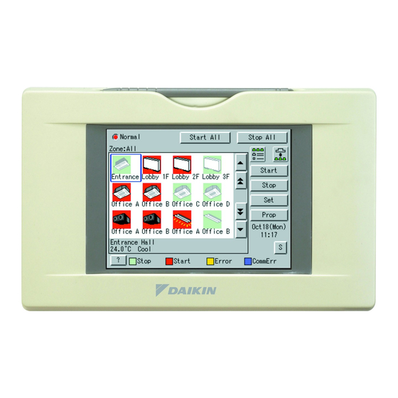
Part Names and Functions Front and Side View PCMCIA Card Slot Color LCD with Touch Panel Touch Pen Used when using the optional Provides a display for monitoring Use the touch pen for operation. and operation. Power Proportional Distribution Be sure to use the touch pen for Be sure to use the touch pen (DCS002C51) or updating the operation. - Page 8 Terminals on the Back of intelligent Touch Controller Terminal block for power supply Connect to AC100-240V power supply. RS232-C connector for Terminal size is M4. DIII-NET Plus adapter Modem connector for AIRNET Using DIII-NET Plus adapter When using AIRNET service, being sold as an accessory, connect it to the telephone line.
-
Page 9: Screen And The Functions List
Part Names on the Monitoring Screen and the Functions List Contents of the List Currently Displayed Zone / Group Currently Displayed Display Mode Selection • When Group List is displayed Press the button and display The name of the zone / group currently selected is highlighted change between Zone and Group. - Page 10 List Display for Collective Monitoring of Air Conditioners Connected to intelligent Touch Controller Start All Button When operation is normal and any air conditioner is in operation : Button to collectively start all the Red / Normal air conditioners connected to When operation is normal and all air intelligent Touch Controller.
-
Page 11: Icon
Icon Contents of the List Currently Displayed Display Mode Selection Zone / Group Currently Displayed • When Group List is displayed Select between Zone and Group. The name of the zone / group currently “Zone : Zone Name” selected is highlighted in blue flame. •... -
Page 12: Operation
Icon Display for Collective Monitoring of Air Conditioners Connected to intelligent Touch Controller Start All Button When operation is normal and any air conditioner is in operation : Button to collectively start all the Red / Normal air conditioners connected to When operation is normal and all air intelligent Touch Controller. - Page 13 Icon Contents of the List Currently Displayed Zone / Group Currently Displayed Display Mode Selection • When Group List is displayed The name of the zone / group currently Press the button ana display “Zone : Zone Name” selected is highlighted in blue frame. change between Zone and Group.
- Page 14 Icon Display for Collective Monitoring of Air Conditioners Connected to intelligent Touch Controller Start All Button When operation is normal and any air conditioner is in operation : Button to collectively start all the Red / Normal air conditioners connected to When operation is normal and all air intelligent Touch Controller.
- Page 15 Quick Reference Air Conditioner Operation ■ To collectively start / stop the operation of all devices connected See page to the intelligent Touch Controller ■ To start / stop the operation of devices by group See page ■ To start / stop the operation of devices by zone See page ■...
- Page 16 System Setup Menu ■ To change the name of a group See page ■ To change the zone setup See page ■ To change the schedule setup See pages ■ To change the change over settings See pages ■ To change the temperature limit settings See pages ■...
-
Page 17: Air Conditioner Operation
Air Conditioner Operation Starting / Stopping Operation Collectively To start / stop the operation Screen 1 Monitoring of all devices connected Start or stop collectively the operation of devices connected. On the Monitoring screen, operation is allowed with either Zone or Group as the display mode and with either Icon or List as the display type. - Page 18 Starting / Stopping Operation by the Group To start / stop the operation Screen 1 Monitoring of devices by group Start or stop the operation of air conditioners by group. The example on the left shows the screen for starting / stopping the operation of Group Name : 1F North registered for Zone Name : Canteen.
- Page 19 Starting / Stopping Operation by the Zone To start / stop the operation Screen 1 Monitoring of devices by group Start or stop by zone the operation of groups of air conditioners set in zones. The example on the left shows a screen for starting or stopping the operation of air conditioners in the canteen.
- Page 20 Switching the Operation Mode Switch the operation mode of the air Screen 1 Monitoring conditioner. On the Monitoring screen, operation is allowed with either Icon or List as the display type. The operation mode can be switched by zone or by group. Selecting a zone and switching the operation mode switches the mode of all air conditioners in the zone.
- Page 21 Changing the Temperature Setting Change the temperature setting of air conditioners. Screen 1 Monitoring On the Monitoring screen, operation is allowed with either Icon or List as the display type. The temperature setting can be switched by zone or by group. Selecting a zone and changing the temperature setting changes the setting of the air conditioner groups in Cool, Heat, Auto or Temp operation in...
- Page 22 Resetting the Filter / Element Sign Screen 1 Monitoring Reset the filter or element sign after cleaning any air conditioner showing the filter or element sign. On the Monitoring screen, operation is allowed with either Icon or List as the display type.
- Page 23 Changing the Direction / Fan Speed Screen 1 Monitoring Change the fan direction or volume of air conditioners. On the Monitoring screen, operation is allowed with either Icon or List as the display type. The fan direction or volume can be changed by zone or by group.
- Page 24 Changing the Range of Operation Allowed with Remote Control Screen 1 Monitoring Change the setting of operation with the remote control of air conditioners between Permitted and Prohibited. On the Monitoring screen, operation is allowed with either Icon or List as the display type. The setting between Permitted and Prohibited can be changed by zone or by group.
- Page 25 Set Ventilation Mode Screen 1 Monitoring (Icon) Perform the following procedure to switch the ventilation mode. For this operation, you can select any of three display types, icon, detailed icon and list on the monitoring screen When changing the ventilation modes of all the ventilation groups of a zone, select the zone and switch the ventilation mode.
- Page 26 Set Ventilation Volume Screen 1 Monitoring Perform the following procedure to change the ventilation volume. For this operation, you can select any of three display types, icon, detailed icon and list on the monitoring screen. When changing the ventilation volumes of all the ventilation groups of a zone, select the zone and switch the ventilation volume.
- Page 27 Permit / Inhibit setting of Ventilation Remote Control Operations Screen 1 Monitoring Perform the following procedure to enable or disable the ventilation remote control operations. For this operation, you can select any of three display types, icon, detailed icon and list on the Monitoring Screen.
-
Page 28: Monitoring Operation Of Air Conditioner
Monitoring Operation of Air Conditioner Monitor Zone or Group Operation Status Screen 1 Monitoring (Icon Display) Monitor Zone or Group Operation Status To monitor the operation status, the monitoring screen permits you to choose any of three display types, icon, detailed icon or list. - Page 29 Monitor Zone or Group Operation Status Screen 4 Legend Description At 9 , you can monitor at a glance the operation status of all air-conditioners connected to the Intelligent Touch Controller. When no problem is found and one or more air-conditioners are operating : Display in red When no problem is found and air-conditioners are not operating : Display in green...
- Page 30 Monitoring Detailed Information Monitor Operation Status of a Zone or Group in Detail Screen 1 Monitoring (Icon Display) When monitoring the operation status in detail, you may choose any of three display types, icon, detailed icon and list. You may monitor the details of the operation status in units of zones or groups.
- Page 31 Monitoring Detailed Information Screen 4 Monitoring Screen (Icon Display) Push [Prop] button 17 . The following maintenance data is displayed on the Detailed Information Screen Screen 5. Note that screens in the left-hand column are examples for group selection. [For group selection] Name : Group name Detailed name : Detailed group name Type : Air-conditioner / ventilation / D3Dio / D3Di...
- Page 32 Monitoring Detailed Information Monitor Ventilation Status of a zone or group in Detail Screen 1 Monitoring (Icon) When monitoring the operation status in detail, you may choose any of three display types, icon, detailed icon and list. You may monitor the details of the operation status in units of zones or groups.
- Page 33 To set / release the lock of screen operation Screen 1 Monitoring (Icon) Lock and Unlock Operations on the Screen You may use a password to lock and unlock operations on the screen. To make this lock / unlock setting, you have to assign an unlock password on P57 beforehand.
-
Page 34: System Setup Menu
System Setup Menu The System Setup menu includes the following items: Atm Control : System menu : • Schedule Setup • Password Setup • Change Over Settings • Time setup • Temperature Limit Settings • Backlight Setup • Heating Optimization Settings •... - Page 35 System Setup Operation Description Menu Item (Reference) See page A backlight is used for the LCD of the intelligent Touch Controller. The backlight Backlight has its service life and the luminance of the backlight is reduced in proportion to Setup the period of time it is illuminated.
- Page 36 System Setup Operation Description Menu Item (Reference) See page This menu permits you to select a language from the list displayed on the Locale Intelligent Touch Controller. Setting By setting locale, you can display data in the selected language on the Intelligent Touch Controller.
- Page 37 System Setup Operation Description Menu Item (Reference) This menu permits you to make settings for the scheduled operations in units of zones or groups. Setting The scheduled operations are used to automatically start or stop an Schedule air-conditioner at the date and time (year, month, day, day of the week, hour and minute) previously set in the Intelligent Touch Controller according to the Outline operating conditions of the air-conditioner.
- Page 38 Operation System Setup Description (Reference) Menu Item See pages 3. [Set events for zone 2F.] Setting (Note) The following lists the events for reference. Scheduled Change the settings according to the actual use conditions. Event Setting events for Monday to Friday Time Target zone Start/stop...
- Page 39 System Setup Operation Description Menu Item (Reference) See page This function allows the optimal room temperature to be maintained without the users Change having to change the operation mode by automatically switching the air conditioner’s Over operation mode (cooling or heating) according to the room temperature for locations Settings where the temperature difference during the day and at night is very large.
- Page 40 System Setup Operation Description Menu Item (Reference) See page < Control Implementation Conditions > Change The relationship between the main room temperature, the main set temperature, Over and the operation mode is described below, with examples. Settings (Two examples are given, as the operation differs for temperature differences 2°C and below and 3°C...
- Page 41 System Setup Operation Description Menu Item (Reference) See page The control instruction is sent to the indoor units registered in the automatic cooling / Change heating switch group when the control implementation conditions shown on the Over previous page are satisfied. The actual control instructions sent differ according to the control method setting (fixed air conditioner / operating air conditioner selection / Settings average) and the satisfied conditions (switch from cooling to heating, etc.).
- Page 42 System Setup Operation Description Menu Item (Reference) See page Change <Precautions when using this control> 1.Do not use the set temperature restriction function in indoor units which are subject Over to control. Settings If it is used, operation modes will be switched and the set temperature will be changed repeatedly, possibly causing the air conditioners to break down.
- Page 43 System Setup Operation Description Menu Item (Reference) See page 4.Because this control automatically switches the operation mode, if the air Change conditioner is not a cooling / heating free unit, always register indoor units which have Over the right to select cooling or heating for the same cooling system to the same Settings automatic cooling / heating switch group, when controlling indoor units which do not have such rights.
- Page 44 System Setup Operation Description Menu Item (Reference) See page This function automatically starts and stops air conditioners in order to prevent the Temperature room temperature of unmanned rooms from getting too high or too low. For example, Limit This has the following advantages. Settings •...
- Page 45 System Setup Operation Description Menu Item (Reference) See page Temperature 3 : Control Implementation Conditions The relationship between room temperature, upper / lower limit, and operation Limit mode is shown below. Settings The controls are implemented when the control conditions are satisfied, every 5 minutes from the time the power is turned on.
- Page 46 System Setup Operation Description Menu Item (Reference) See page Temperature 4 : Precautions for the use of this control The operation modes are switched over automatically with this control. Therefore, if Limit the air conditioners are not cooling / heating-free machines, and when an indoor unit Settings without cooling / heating selection right is to be controlled, be sure to register an indoor unit with cooling / heating selection right in the same cooling system into the...
- Page 47 Description Menu Item (Reference) See page With the air conditioners made by Daikin (Buil-Mul or Building multi Heating indoor unit), when the thermo-switch is turned off (the compressor is Optimization off) during heating operation, the fan does not stop. (It continues to Setting run at the minimum speed, or at the speed set in the heating mode.)
- Page 48 System Setup Operation Description Menu Item (Reference) See page 2 : Control execution condition Heating The relationship between room temperature, set temperature, and operation / Optimization stop status is shown in the figure below. Setting The operation period of the control is every 5 minutes after the system power is turned on, and the operation is executed when the control conditions are met at each timing.
- Page 49 Operation System Setup Description (Reference) Menu Item See pages E-mail Setting This option is used to, when the Intelligent Touch Controller detects a malfunction in such as the air-conditioning unit (*1), send an e-mail containing the date, the error * The e-mail code and so on to the pre-registered administrators at three different addresses function is maximum.
- Page 50 Operation System Setup Description Menu Item (Reference) Timing of E-mail Sending See pages Referring to the figure below, timing of sending e-mails is described. [Send when a malfunction occurs in the normal state] If a malfunction occurs in the destination groups defined in the e-mail sending, wait three minutes from the malfunction ( 1 in the figure below) before sending an e-mail.
- Page 51 From : user012@daikin.co.jp Originating e-mail address Destination e-mail address To : user012@daikin.co.jp Subject : Fault occurs (DAIKIN Head Office) Fixed string of characters and controller name 04/02 14:11 Office A9 Date of occurrence of the malfunction (month, day,...
- Page 52 Operation System Setup Description Menu Item (Reference) See pages Simple This menu is used to make settings of an interlock control function in units of zones or groups. Interlock The simple interlock control is a function to automatically control groups or zones Setting corresponding to a change of the operation states or the stop states in any groups.
- Page 53 System Setup Operation Description (Reference) Menu Item See pages Control operations when a communication error occurs in the interlock input points Example 1) When a communication error occurs in any of the interlock input points, the condition will be checked only for the interlock input points in the 1-00 1-01 1-02...
- Page 54 Operation System Setup Description Menu Item (Reference) See pages In the following section, utilization of the simple interlock control function is described while giving some examples. Referring to the figure below, the setting examples of the simple interlock control program are provided. [Example 1 of interlock control] When any of the air-conditioning units on the second floor (1-00, 1-01) start operating, HRV (1-02) will be started.
- Page 55 System Setup Operation Description (Reference) Menu Item See pages • Limitations of the simple interlock function In the simple interlock function, setting the inconsistent input/output conditions is allowed as described below. * Priority of the interlock programs is determined in such a way that the lower program has a higher priority and the output 2 has a higher priority than the output 1.
- Page 56 Operation System Setup Description Menu Item (Reference) Simple Interlock See page [Change the name of the simple interlock program] Change Name You can change the name of the simple interlock program to the understandable one. Simple Interlock See page [Determine the validity / invalidity of the simple interlock setting] Validity / Invalidity Lastly, whether the simple interlock setting is valid or invalid can be specified.
-
Page 57: Maintenance
System Setup Operation Description Menu Item (Reference) See page This menu should be displayed on the screen stored in the memory of History intelligent Touch Controller and used to store data in memory card Display (customer-arranged). See page Menu for adjusting the positions of buttons on the touch panel used as the Touch Panel screen of the intelligent Touch Controller. - Page 58 System Setup Menu Operation Screen 1 Monitoring Screen Viewing the System Setup Menu Screen Press the [S] button 1 on Screen 1 Monitoring. Screen 2 System Setup Menu (see lower left) appears. If a password is set, the screen does not appear unless the password is entered.
- Page 59 System Setup Menu Operation Password setup Screen 1 Password Setup Select Password Setup as described on page 56. Screen 1 Password Setup, which is shown on the left, appears. Select Enable or Disable for password Protection 1 . If Disable is selected, press the [Close] button 2 .
- Page 60 System Setup Menu Operation Time setup Screen 1 Time Setup Select Time Setup as described on page 56. Screen 1 Time Setup, which is shown on the left, appears. Press the [Modify] button 1 . Time setting dialog in Screen2 is displayed.
- Page 61 System Setup Menu Operation Backlight setup Screen 1 Backlight Setup Select Backlight Setup as described on page 56. Screen 1 Backlight Setup, which is shown on the left, appears. Press Enable or Disable for Backlight Auto Off 1 . If you select Disabled, go to step 6. Caution For longer service life of the backlight, select Enable whenever the backlight does not need...
- Page 62 System Setup Menu Operation Screen 1 Group Setup Group setup Select Group Setup as described on page 56. Screen 1 Group [Setup], which is shown on the left, appears. Select the group to be set with 1 . Press the [Setup] button 2 . Group setup in Screen 2 is displayed.
- Page 63 System Setup Menu Operation Screen 1 Zone Setup Zone setup Select Zone Setup as described on page 56. Screen 1 Zone Setup, which is shown on the left, appears. To add a zone, press the [Add] button 1 . A zone is added with the name Z-000.
- Page 64 System Setup Menu Operation Screen 3 Registered Groups Edit Zone setup 2 Set the groups to be registered for the zone currently selected. To add a group to the zone, select the group to be added with 17 and press the [<<] button 18 .
- Page 65 System Setup Menu Operation Screen 1 Network Setting Network Setting Select “Network Setting” according to the operating procedure shown in page 56. Confirm that the Network setting screen Screen 1 will be displayed as shown in the left-hand column. Push the [Modify] button 1 and enter a Host name on the resulting input screen.
- Page 66 System Setup Menu Operation Screen 1 Setting of icon color Icon Color Setting Select “Setting of icon color” according to the operating procedure shown in page 56. Confirm that the Setting of icon color screen Screen 1 will be displayed as shown in the left-hand column.
- Page 67 System Setup Menu Operation Screen 1 License key input License Key Input Select “License key input” according to the operating procedure shown in page 56. Confirm that the License key input screen Screen 1 will be displayed as shown in the left-hand column. Push the [Add] button 1 and input an option software license key on the resulting keyboard dialog.
- Page 68 System Setup Menu Operation Screen 1 Schedule Setup Set Schedule and Calendar Before setting a calendar, refer to page 35 to consider what kind of schedule is to be set and perform the following operations. The following shows an example of setting made referring to zone 2 in page35.
- Page 69 System Setup Menu Operation Screen 1 Schedule Setup Set Schedule and Event Before setting an event, refer to page 36 to determine what kind of event is to be set and perform the following operations. The following shows an example of setting made referring to page 36.
- Page 70 System Setup Menu Operation Screen 3 Event Setup A full description of each button has been given above. The following discusses how to make the actual settings. To define the new operation, push the [Add] button 4 . To change the previously set operation, push the [Modify] button 6 .
- Page 71 System Setup Menu Operation Screen 4 Advanced Setup Push the [Advanced setting] button 18 on the Event setup screen Screen 3 to display an advanced setup screen Screen 4. The current settings of events are shown at the left side of the buttons 21 to 24 .
- Page 72 System Setup Menu Operation Screen 1 Schedule Setup Change Schedule Name Select “Schedule Setup” according to the operating procedure shown in page 56. Confirm that the Schedule setup screen Screen 1 will be displayed as shown in the left-hand column. Select a schedule from the list 1 to change the name.
- Page 73 System Setup Menu Operation Screen 1 Schedule Setup Convenient Function 1 Copy in Units of Events ∗ When it is necessary to reuse an event set for a day of the week, this function greatly helps you copy the event to the other day of the week.
- Page 74 System Setup Menu Operation Screen 1 Schedule Setup Convenient Function 2 Copy or Delete in Units of Schedules ∗ When it is necessary to resume a calendar setting made for schedule 1, this function greatly helps you copy the calendar setting to the other schedule(s).
- Page 75 System Setup Menu Operation Operation of Change Over Settings Screen 1 Change Over Settings Before performing Change Over Settings, read thoroughly the section Change Over Settings on page 37, and perform the following procedure. See page 56 and select Change Over Settings. Screen 1 Change Over Settings, which is shown on the left, appears.
- Page 76 System Setup Menu Operation Operation of Temperature Limit Settings Screen 1 Temperature Limit Settings Before performing Temperature Limit Settings, read thoroughly the section Temperature Limit Settings on page 42, and perform the following procedure. See page 56 and select Temperature Limit Settings Screen 1 Temperature Limit Settings, which is shown on the left, appears.
- Page 77 System Setup Menu Operation Operation of Heating Optimization Settings Screen 1 Heating Optimization Settings Before performing Heating Optimization Settings, read thoroughly the section Heating Optimization Settings on page 45, and perform the following procedure. See page 56 and select Heating Optimization Settings. Screen 1 Heating Optimization Settings, which is shown on the left, appears.
- Page 78 System Setup Menu Operation Screen 1 History Check for History Select “History” by using the operation method described on page 56. The History screen Screen 1 appears as shown in the left-hand column. When checking for the history of system setup operations, touch the [Operation History] button 1 to confirm that the Operation history screen Screen 2 is displayed.
- Page 79 System Setup Menu Operation Screen 1 Touch Panel Calibration Touch Panel Calibration See page 56 and select Touch Panel Calibration. Screen 1 Touch Panel Calibration, which is shown on the left, appears. Follow the instruction shown on the screen and press the intersection of the crosshairs 1 and keep it pressed for about 1 second.
- Page 80 System Setup Menu Operation Screen 3 Setting of E-mail transmission Push the [Modify] button 13 and enter a retransmission interval on the input screen. The retransmission interval is an e-mail retransmission interval when faults occur consecutively with the equipment. This interval time (hour) must be a value from 1 to 72.
- Page 81 System Setup Menu Operation Screen 1 linkage Setup Simple linkage Settings Following the steps described on page 56, select the simple linkage settings. As shown in the figure of the Screen 1 on the left side, the linkage Setup setting screen will be displayed.
- Page 82 System Setup Menu Operation Screen 4 Advanced setting In the Screen 3 Event setting on the previous page, pressing the [Advanced setting] (See 14 ) will display the Advanced setting screen shown in the Screen 4 on the left side.?The information displayed in the boxes pointed by 17 to 20 is the current settings of the event.
- Page 83 System Setup Menu Operation Screen 5 Simple linkage Setup Simple Interlock Change Name Following the steps described on page 56, select the simple interlock settings. As shown in the figure of the Screen 5 on the left side, the simple linkage setup screen will be displayed.
- Page 84 System Setup Menu Operation Screen 1 Version Information Version Information This is a menu for checking the version number of the software for the intelligent Touch Controller currently used. Generally it is not necessary to check. See page 56 and select Version Information.
-
Page 85: Precautions
Precautions Internal Battery Enable (ON) / Disable (OFF) Switch The intelligent Touch Controller is equipped with internal batteries in order to run the clock during blackouts as well as to save data during blackouts when using the optional Power Proportional Distribution. -
Page 86: When Leaving The Product Turned Off For A Long Time
Maintenance LCD Maintenance • When the surface of the LCD or the main unit of the intelligent Touch Controller is soiled, wipe the soil off with a piece of cloth soaked in a diluted neutral detergent and wrung sufficiently. Note Do not use thinner, organic solvent, strongly acid solution, etc. -
Page 87: Troubleshooting
Troubleshooting Before Having the Product Serviced Item Description and Corrective Action When Backlight Auto OFF is set for Backlight Setup of the The display of the intelligent intelligent Touch Controller, the light goes out if the screen is Touch Controller has gone out. left untouched for a certain time. - Page 88 Before Having the Product Serviced Item Description and Corrective Action On the Monitoring screen, The intelligent Touch Controller is designed in such a way that buzzer sounds when an area the buzzer sounds when any part of the screen is pressed. It is normal.
- Page 89 Before Having the Product Serviced Item Description and Corrective Action Is the indication System Ctal Mng on the Monitoring screen, as Collective Operation, Start and shown below? Stop buttons are not shown on This indication is shown in the following cases. the Monitoring screen of the intelligent Touch Controller and When iPU, BAC net Gateway is connected to the intelligent...
- Page 90 Before Having the Product Serviced Item Description and Corrective Action The air conditioner is The followings are possible causes. Check the followings. 1. Is the stop operation performed with the remote control of the supposed to operate, but it is air conditioner? stopped.
- Page 91 Before Having the Product Serviced Item Description and Corrective Action Collective Operation, Start and Is the indication System Compulsory Stop on the Monitoring screen, as shown below? Stop buttons are not shown on This indication is shown in the following cases. the Monitoring screen of the When compulsory stop command is input to central management intelligent Touch Controller and...
- Page 92 Before Having the Product Serviced Item Description and Corrective Action The air-conditioning unit does The air-conditioning unit might be stopped by the simple interlock control function. not operate. Check the settings of the simple interlock function. In the case described below, the air-conditioning unit : 1-01 will not operate.
- Page 93 Emergency Procedure for intelligent Touch Controller Failure Item Description and Corrective Action Failure occurs in the intelligent As a temporary measure before our service personnel investigates into the problem, turn OFF the power supply Touch Controller while the breaker of the intelligent Touch Controller. This allows all remote control is disabled with kinds of operation with the remote control of air conditioners in the intelligent Touch Controller...
- Page 94 When it is desired to adjust screen brightness, contrast and buzzer sound level Item Description and Corrective Action Screen brightness, contrast The screen brightness, contrast and buzzer sound level are factory adjusted properly before shipment, but in case where and buzzer sound adjustment the screen is hard to see and the buzzer is hard to hear, for is desired.
-
Page 95: Options
Options Connecting Unification adaptor allows using the contact for normal and abnormal operation signal and collective start/stop with a contact. For details, contact the vendor you purchased the product from. Also, by connecting DIII NET-plus adaptor, it is possible to operate and monitor the indoor units of 64 groups (intelligent Touch Controller plus DIII NET –... -
Page 96: Specification
Specification Specification Power AC100 - 240V 50/60Hz 10 W maximum Power consumption Normally-open contact Force stop input Contact current approximately 10 mA 230 × 147 × 107 (W × H × D) Size 1.2kg Mass Dimensions The specification and appearance of the product may be modified for improvement without prior notice. -
Page 97: After-Sales Service
After-sales Service After-sales Service • To have the product repaired, • Repair after the guarantee period for prepare the following information free repair Contact the vendor. When the functions can be • Model maintained by repair, the product will be repaired •... - Page 98 Daikin Europe N.V. is approved by LRQA for its Quality Daikin units comply with the European regulations that Management System in accordance with the ISO9001 guarantee the safety of the product. standard. ISO9001 pertains to quality assurance regarding design, development, manufacturing as well as to services related to the product.
Need help?
Do you have a question about the DCS601C51 and is the answer not in the manual?
Questions and answers
If i forget the password how can open the itc and reset password
If you forget the password for the Daikin DCS601C51 Intelligent Touch Controller (ITC), you cannot perform any system operations. To reset the password, you must contact a dealer in your area.
This answer is automatically generated