Table of Contents
Advertisement
Quick Links
- 1 Table of Contents
- 2 Control Systems
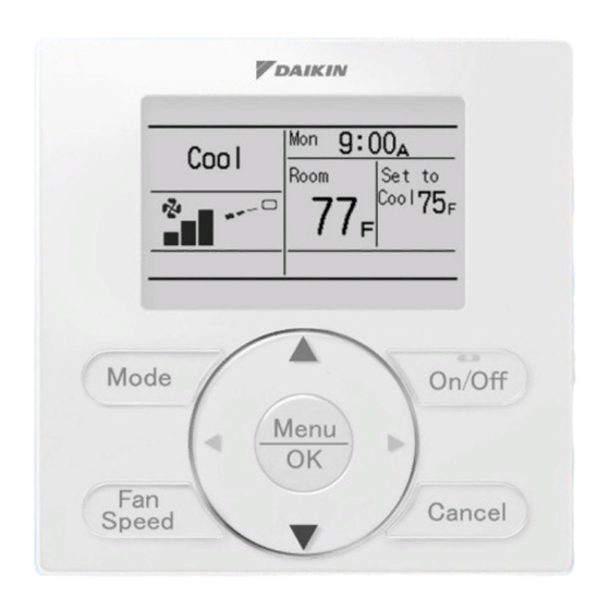
- 3 Brc1E71 Navigation Remote Controller (Wired Remote Controller)
- 4 Brc4C / 7C / 7E Wireless Remote Controller / Receiver
- 5 Dcs601C71 Intelligent Touch Controller
- 6 Dta104A53 / 61 / 62 External Control Adapter for Outdoor Unit (Must be Installed on Indoor Units)
- 7 Krp1C74 / 75 Wiring Adapter
- Download this manual
Advertisement
Table of Contents


Need help?
Do you have a question about the FXFQ-PVJU and is the answer not in the manual?
Questions and answers