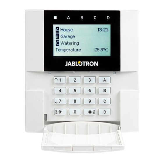
jablotron JA-10 Series Manual

jablotron JA-10 Series Manual

Control panel
Hide thumbs Also See for JA-10 Series:
Table of Contents

Advertisement

JA-14K(R) Security System Control Panel
A control panel is a fundamental part of the JA-10 series alarm system and is designed to protect small,
medium or large premises and it offers a lot of parameters and also the system profiles compliy with security
grade 2 requirements.
The control panel has BUS and/or wireless device (when the control panel is equipped with a radio module)
compatibility. It is recommended that only JA-10 devices are used with the system. Proper functionality cannot
be guaranteed when using third party devices.
Caution: The JA-10 security system can only be installed by a trained technician with a valid certificate issued
by an authorized distributor.
The manual is intended for trained technicians and is valid for control panel firmware LJ60422 and
N-Link configuration software 2.0.0 or higher.

Advertisement

Table of Contents
loading
Need help?

Need help?

Do you have a question about the JA-10 Series and is the answer not in the manual?

Questions and answers

Subscribe to Our Youtube Channel

Summary of Contents for jablotron JA-10 Series

  • Page 1 JA-14K(R) Security System Control Panel A control panel is a fundamental part of the JA-10 series alarm system and is designed to protect small, medium or large premises and it offers a lot of parameters and also the system profiles compliy with security grade 2 requirements.
  • Page 2: Table Of Contents

    Contents 1 Basic description and definitions ........................4 Basic system configuration requirements ..................6 Access codes and their default settings ..................... 7 1.2.1 Change of access codes ..................... 8 1.2.2 Security access codes and RFID devices ................8 Regular system check (maintenance) ....................9 2 System size ..............................
  • Page 3 9.14 Disabling and blocking options ......................39 9.14.1 Disabling ..........................39 9.14.2 Blocking ..........................40 9.15 Non-alarm functions – Functions of PG outputs ................40 10 Setting the system through N-Link SW ......................40 10.1 Starting the N-Link software and setting the system size ..............42 10.2 Sections tab ............................
  • Page 4: Basic Description And Definitions

    1 Basic description and definitions Modular architecture – Allows the system to be configured for specific installations, sizes and user needs. Firmware (FW) update – procedure for updating to a new FW version into the system containing new functions, improvements and adaptations. We recommend you check that FW is up-to-date during any installation as well as during regular service checks.
  • Page 5 (ARC) service that is equipped with reception technology for the Jablotron IP protocol. In the control panel settings you can select which communication type will be primary and which will be used as a backup.
  • Page 6: Basic System Configuration Requirements

    that it has been recognized, but it doesn´t change its status (a fault is still present in the system). The function depends on the option given by the parameter ‘Ways of setting’. Blocking - it blocks an active device input to activate a PG output or to perform any reaction activation. Perform blocking manually by keypad or N-Link.
  • Page 7: Access Codes And Their Default Settings

    Default Factory pre-set profile, all system parameters are optional. EN 50131-1, Grade 2 Profile pre-sets some specific system parameters (valid for control panel, keypads, sirens, etc.) according to the given norm requirements valid for security grade 2. In relation to alarm reporting, and considering the selected profile valid for security grade 2, the control panel has to be installed according to one of the following configurations as a minimum: Ways of reporting System profile and adequate configuration...
  • Page 8: Change Of Access Codes

    Codes for JA-14K(R) EN50131-1 profile, Default profile (4-digit codes) (6-digit codes) Code format: nnnn nnnnnn Service (default): 1010 101010 Administrator (default): 1234 123456 ARC code: 1000 100010 Warning: When the system profile setting is changed, all defined codes are erased and only default codes are are pre-set to default values.
  • Page 9: Regular System Check (Maintenance)

    Protection against a code breaking attempt: The control panel counts the attempts at wrongly entered codes and if the 10 attempt is reached, the system triggers the tamper event “Code breaking attempt”, alarm is triggered and reports this event to predefined numbers.
  • Page 10: System Size

    2 System size The control panel can be split into 4 sections (independently adjustable parts). Every device has its own address (keypads, detectors, sirens) and has to be enrolled to a section. Authorisation to access some of the defined sections has to be added to each user. Sections can be linked to other sections (common section) to control them and their statuses together.
  • Page 11: The Ja-14K(R) Control Panel Utility Parameters

    3 The JA-14K(R) control panel utility parameters The very basic component of the JA-10 system is the JA-14K(R) control panel. Its basic parameters are summarized in the table below: Tab. 1 Feature / Type JA-14K(R) Note It is the sum of wireless Maximum number of devices and BUS components Maximum number of users...
  • Page 12 1 - Back-up battery 2.6 Ah; 2 - Control panel PCB; 3 - GSM antenna of a supplementary GSM dialler; 4 - Transformer; 5 - Mains power terminals, 200 mA fuse; 6 - Tamper contact of the housing; 7 – JA-111R radio module; 8 - USB connector for PC connection 1 - Connector for supplementary modules (GSM or PSTN communicator);...
  • Page 13: Indication Leds On The Control Panel Board

    Parts of the JA-14K control panel (changeable parts) are: − MicroSD card 4GB or higher – meant as storage to save events, pictures from PIR detectors and cameras To extend control panel options use: − The JA-111R radio module (from default pre-installed in the JA-14KR kit) −...
  • Page 14: Before System Installation

    4 Before system installation Select a hidden place for the control panel (inside the protected area) where mains supply is available. The mains supply of the control panel may only be installed by a person with the required electrical qualifications. The manufacturer doesn´t allow people to power the control panel up from other alternate power supply sources such as high capacity batteries charged by solar energy and so on.
  • Page 15: Bus

    The BUS of the JA-10 system consists of four wires (4-wire). The BUS cannot be shared with another system not even to power different devices. terminal colour note positive power supply terminal; it can only be used to supply devices of the JA-10 series yellow data A green data B BUS terminal board...
  • Page 16: Power Supply Requirements

    The JA-14K(R) type is more suitable for wireless systems or also as a hybrid system. When planning the configuration of a wireless control panel, do not forget to include the radio module(s) in the consumption. Parameter JA-14K(R) 400 mA permanently Maximum permanent current from BUS (1000 mA for 5 min) 125 mA...
  • Page 17: Installation Of A Ja-111R Radio Module

    6.1 Installation of a JA-111R radio module 1. The module can be placed in the control panel cover or it can be installed elsewhere in the building and connect it with a BUS cable. If the module is installed in the control panel cover, connect it to the internal BUS connector using a flat cable equipped with RJ connectors.
  • Page 18: Switching The System On

    7 Switching the system ON 1. Check connection of the BUS cables. 2. Verify whether a microSD card is present in its holder on the control panel board. 3. Check whether the mains supply cable is correctly connected to the control panel and that the supply cable is firmly fixed.
  • Page 19 System parameter overview when the „DEFAULT“ system profile is set: Device Parameter Option Blocking (limitation) Control panel Siren when partialy set (IW) Control panel Sirens enabled Control panel Administrator – restricted Service/ARC rights Control panel Service and ARC controls the system Control panel Duress access control Control panel...
  • Page 20 System parameter overview when “EN 50131-1, grade 2”, is set: Device Parameter Option Blocking (limitation) Control panel Siren when partialy set Control panel Sirens enabled Control panel Administrator – restricted Service/ARC rights Control panel Service and ARC controls the system Control panel Duress access control Control panel...
  • Page 21 Global overview of reasons preventing setting according to the pre-set system profile: EN 50131-1, Event Default profile Grade 2 Passable Impassable Passable Impassable Active tamper Active input (any input) Active instant input Active alarm memory indication RF device 20 min no response Siren fault Fault Loss of a device...
  • Page 22: Control Panel Operation Modes

    8.2 Control panel operation modes Security system has a few operation modes. Switching between modes depends on users authorisation levels. MODE Description A mode in which no alarm can be triggered. It is only meant for a service technician or an ARC technician and it is for enrolling new devices and system configuration.
  • Page 23 Code Type Description authorization This code has the highest level of authorization to configure the system’s behaviour and is exclusively allowed to perform the system unblock after a triggered alarm. It can enter Service mode, access all tabs with options including ARC communication to which it can deny access to a Service technician (Service code).
  • Page 24: System Optional Parameters (N-Link - Parameters Tab)

    8.4 System optional parameters (N-Link – Parameters tab) Siren when partially set IW – This function which allows the activation of internal sirens during an intrusion alarm (it is not related to Fire or 24hr alarms) when the system is partially set. Sirens enabled –...
  • Page 25 b. By connecting the battery to a wireless device - however, at least one radio module must be enrolled first. Remote controls of the JA-16J type are enrolled by pressing of both upper buttons. c. By entering the serial number in the SN production code field (it is found under the barcode on the board inside the device, e,g.
  • Page 26: List Of Applicable Reactions

    8.4.2 List of applicable reactions In the Devices tab you can set the reaction of the system activation of an enrolled device. Only such types of reactions are offered for individual devices that make sense for the particular product. There are some devices that cannot be assigned any reaction (e.g.
  • Page 27: Limitation Of False Alarms

    8.4.3 Limitation of false alarms In installations with an increased risk of false alarms special reaction types can be used: Confirmed intrusion reaction – if in a set section a detector with confirmed reaction is activated, the system only reports an unconfirmed alarm to the ARC and waits for confirmation by another detector. The alarm may be confirmed by any intrusion detector in a set section.
  • Page 28: Intrusion Alarm

    In the following table is an overview of IW and EW outputs according to the type of alarms and section status: Alarm type System Settings - Parameters Activates Siren IW during IW siren on case Section status partial set of tampering Unset Partially set 8.5.1 Intrusion alarm...
  • Page 29: 24Hr Alarm

    1) Silent panic – a special event not assigned to a group of intrusion alarms, which would be indicated by a siren or keypad. A silent panic has no timer and there is no end to this event. So it cannot be used for the status control of a PG output.
  • Page 30: Fault Caused By Loss Of A Device

    8.7 Fault caused by loss of a device Every device in the system is supervised by the control panel. BUS devices are supervised allways, wireless devices regarding the Parameters tab / Supervision of wireless device checkbox. When the communication with the device is lost (no response within a pre-set time) then the system triggers the event “Fault activation”.
  • Page 31: System Control By Keypad

    To adjust the security level the authorization level can be pre-set at the following 2 levels: 1. Standard – authorization is performed by applying an RFID tag or entering a valid access code 2. Double authorization - Entering a user code and using an RFID tag will accomplish valid authorization. For authorization on the system keypad it is always required to enter a valid access code and RFID tag (regardless of the order of authorization).
  • Page 32: System Control By Remote Control

    Setting the system: The way of controlling is based on the procedure: “select the required action and authorize yourself”. It is an old style procedure which is not correct for the current norm requirements related to hiding the system status. 1.
  • Page 33 Calendar control options related to guarding: No control function pre-set. It sets pre-set section(s) and starts with an exit beeping time of 180 s (regardless of how long the exit time has been set in the control panel), within this time all alarm zones behave like a delayed zone.
  • Page 34: System Control Via Application For Smart Phones

    9.5 System control via application for smart phones The security system can be controlled comfortably by an application for smart phones. The application enables following functions: • check the current system status • set / unset the complete system or parts of it •...
  • Page 35 Control Answer (specimen) Note command and authorization JA-10: Installation name according to the Communication tab TYPE: JA-14K, Control panel type DINFO SN: 14004026532523, Serial number (basic SW: LJ60420, Firmware version information about the HW: LJ16123, Hardware version installation) RC: 79167-5FYA9-ZSQJ, Registration code of GSM communicator GSM: 90%, GPRS:ok, GSM signal quality, GPRS data availability...
  • Page 36: Controlling The System Via N-Link

    JA-10: Installation name according to the Communication tab Status: Status: UNSET Name and status of Section 1 Section 1: Unset; (control of the Name and status of Section 2 Section 2: Unset; whole system) Name and status of Section 3 Section 3: Unset;...
  • Page 37: Obstacles Preventing Setting The System

    9.10 Obstacles preventing setting the system According to Ways of setting (see Parameters tab), the control panel may check for triggered or fault statuses of individual devices or a particular section while setting each section of the system. In line with this option, the control panel indicates some obstacles during setting (passable obstacles) and some of the statuses and may even prevent the system from setting when they occur (impassable obstacles).
  • Page 38: Overview Table Of Groups Of Events Reported To Users

    In the case when setting the system is prevented, an “Unsuccessful setting“ event is triggered and indicated by rapid flashing of the system indicator with a yellow colour on the keypads and also by their beeping, and acoustically by an outdoor siren as well. Simultaneously it is reported to a specific user or to the system administrator if the report “Unsuccessful setting”...
  • Page 39: System Acoustic Indication

    Installation name (see the Communication setup tab): Time (of event occurrence), Event (see table). Event source (see the Devices/Name or User/Name tab), Section (where the event occurred); Time (time and date of sending) Example of a sent SMS: JA-10 (installation name) 17:01:10, Delayed alarm (event time, event) Door magnet, Ground floor...
  • Page 40: Blocking

    The JABLOTRON system is delivered ex works with the communication language option set to “English”. However, other language options of the control panel are limited by a narrower choice of language(s) per the country the control panel is designed for.
  • Page 41 From the web interface, which is only accessible for trained installation technicians: a. Login to the MyJABLOTRON web service www.myjablotron.com b. Open the MyCOMPANY section c. Select the Activation Codes service d. Click on the item + Get new activation code e.
  • Page 42: Starting The N-Link Software And Setting The System Size

    Example of sending a request using an SMS Getting the Activation Code from your distributor. When asking for the Activation Code you will need to provide the registration code of the control panel. Depending on country, the activation code can be also found on the package box of the control panel.
  • Page 43: Devices Tab

    Section name – naming of sections is used to make textual event reports (SMS), showing on keypad and memory readout, for a better recognition when reported (e.g. Ground Floor, Store, ...) Common section – allows you to select that a section is automatically set if all the sections for which it is a common one are set (suitable for corridors, staircases and other common areas).
  • Page 44: Users Tab

    Internal – this parameter is only available for intrusion detectors. Signals from devices with this indication are not evaluated as alarm signals if a section is partially set. Partial setting of a section - see chapter 10.2 Sections tab. Internal settings – access to settings of internal parameters of perimeters that are connected to the BUS or feature bidirectional wireless communication.
  • Page 45: Pg Outputs Tab

    Section – defines which sections may be defined by the user (administrator). The Administrator may also set codes and tags of users in the assigned sections. A section cannot be assigned to a user that is only authorized to control PG outputs. PG –...
  • Page 46: Map Of Pg Output Activation

    Current status – color-coded information about the current status of a PG output. Green description corresponds to the green light of the functional button; red description corresponds to the red light of the button. Test PG output – possibility to control an output manually from the computer using N-Link SW. Depending on the selected function it will enable (or disable) the particular PG, if it´s not currently blocked.
  • Page 47: Users Reports Tab

    Internal statuses for control of PG outputs: 1. Unset 13. Entry delay 25. Annual check request 2. Any set 14. Exit delay 26. GSM fault 3. Partially set 15. AC fault 27. LAN fault 4. Completely set 16. AC fault for 30 minutes 28.
  • Page 48 code has been entered, the alarm is stopped and the next user is not called any more. Voice calling is time- consuming and it can be set for maximum 8 users. For the voice reports universal voice message are pre-set in the system.
  • Page 49: Parameters Tab

    GSM network Time adjustment* Time and date are adjusted automatically according to communication server. Option does From the Jablotron server nothing when the type of communication is set (LAN / GSM) to “Without remote programming” (factory...
  • Page 50 Serves for triggering of a silent alarm by authorization only or by system control (setting, unsetting, PG control, …) when a user is in the presence of a criminal. A Panic alarm is triggered during system control when a code is entered with 1 mathematically added to the last digit’s value.
  • Page 51 Selection from pre-set system profiles according to requirements. Parameters set by factory default with the option to Default modify them according to needs System profiles Some parameters are pre-set automatically to EN 50131-1, Grade 2 comply with EN 50131-1, Grade 2 (low – middle risks) with no option to be modified In each section, the entry and exit delays are measured separately.
  • Page 52: Diagnostics Tab

    Selection of the way the system processes user authorization. Related to controlling a PG output with authorization. Standard Entering a user code, using an RFID tag will accomplish valid authorization. Just of these options is necessary to control the system. Double authorization Entering a user code and using an RFID tag will Authorization type...
  • Page 53 Days of the week – defines on which days the action is executed (e.g. every Monday) Time – Defines at what time the action is executed on the specified day. Guarding – Allows you to execute the actions “Set”, “Partially set” with the variant “Immediately” (no exit delay or acoustic indication) and the variant “Always”...
  • Page 54: Communication Tab

    Notes: − One schedule event can control (enable or disable) setting and PG outputs at the same time. − Switching an application on and off for a certain time is possible in 2 ways. You can either set an action for enabling and an action for disabling the PG output or only an action for enabling and set an impulse of the required length for the PG output.
  • Page 55: Ja-190Y Settings

    Persistent (LAN) – the control panel maintains a permanent data communication with the server, it allows remote connection with the N-Link software is possible. JABLOTRON communication – the device communicates with the manufacturer’s server (MyJABLOTRON application) and continuously sends information about the device status to it. Thus, if the N-Link sends a request for remote connection, the server is immediately ready to establish connection.
  • Page 56: Lan Settings

    No code for voice menu and control SMS – When the user accesses the system, it is not required to enter the code (authorized by its own telephone number). It is necessary to have the caller ID service (CLIP) activated. Credit enquiry –...
  • Page 57: Pstn Settings (Ja-190X)

    DNS server – setting for manual DNS server IP assignment that is only available if automatic assignment from the DHCP server is not enabled. The default setting is 192.168.1.1 MAC address – unique address of every LAN device (identification of data source) LAN device for identification of the source of information Test DNS –...
  • Page 58: Arc Tab

    ARC Technician authorization level. The option is also unavailable if the JABLOTRON communication is selected, which considerably simplifies setting of the communication part of the system. To make changes in this tab you do not need to be in the Service mode.
  • Page 59: Requrements For The Setup Of Transmission Paths To An Arc

    - unique message time stamps inserted - very precise time synchronization between alarm system and ARC 2) Protocol JABLO_IP (data message) - Proprietary Jablotron protocol - 256 bit encryption - unique message time stamps inserted - very precise time synchronization between alarm system and ARC...
  • Page 60: Cid And Sia Codes

    10.11.3 JA-10 CID and SIA codes Event EN Report category 1101 Health problem Burglary 1110 Fire alarm Fire 1118 Unconfirmed fire alarm Fire 1120 Panic alarm Panic 1130 Instant alarm Burglary 1133 24H alarm Burglary 1134 Delayed alarm Burglary 1138 Unconfirmed alarm Burglary 1144...
  • Page 61: Setting The Transmission Of Photos To External Storage

    3154 Flood alarm (deactivation) Tamper 3174 Not used Special reports 3175 Not used Special reports 3176 Not used Special reports 3130 Keybox (deactivation) Special reports 3300 Fault (deactivation) Faults and service events 3301 AC recovery Uncategorised 3302 Control panel backup battery OK Special reports 3306 Service mode exit...
  • Page 62: Other N-Link Options

    11 Other N-Link options The N-Link version is always indicated in the top bar after the name. The toolbar provides brief access to often-used items such as the button for mode changes, system events, settings, the RF signal of radio modules, settings exporting or local and remote access to the control panel. 11.1 System control by N-Link Individual sections in the N-Link SW can be controlled locally or remotely, there are two ways.
  • Page 63: System Settings

    Online events (available also after pressing F7) – in a temporary table all events are recorded that are saved in the event history and that occur after activation of this option, incl. events during service setting. Online signals (available also after pressing of F6) – in a temporary table all signals are recorded that are registered by the BUS (e.g.
  • Page 64: Rf Signal

    11.4 RF Signal Window for graphic representation of radio band interference intensity with the possibility to select from the used radio modules. Presence of unknown signals in the band is indicated in red. Green colour identifies communication signals of the system (enrolled devices) and blue is used to display the selected device from the list of the Highlighted device item (see figure).
  • Page 65: Installation Information

    “empty” database, the registration code and the phone number will have to be added. When a LAN communicator is used and Jablotron communication enabled then the telephone number cannot be filled in. Establishing the connection only takes a few seconds, but the downloading of the configuration depends on the system size and it may usually take 1 to 2 minutes.
  • Page 66: Reset Of The Control Panel

    12 Reset of the control panel You can only restore the default settings of the control panel in the following way if in the N-Link SW in the Parameters tab the Reset allowed item is checked. If Reset is not allowed and you do not know the service code, you cannot reset the control panel and the control panel board must be sent to the distributor.
  • Page 67: Fw Updates For The Control Panel And Devices Connected To The Bus

    13.2 FW updates for the control panel and devices connected to the BUS. In the Firmware Update selection window, updatable BUS and bidirectional wireless devices of the control panel are displayed. N-Link automatically selects devices for which an update is required (they have older FW than in the FW pack).
  • Page 68: Check After A Fw Check

    More detailed information about the existing and new versions of individual devices are displayed in the help bubble after moving the mouse cursor over each of the offered devices. By pressing the OK button you will upgrade all the devices. 10.
  • Page 69: Supplementary Information

    14 Supplementary information 14.1 Overview table of current consumption of BUS devices Consumption in Consumption for Device Note the backup mode cable selection JA-10E LCD keypad 30 mA 110 mA JA-111R Radio module for 25 mA 25 mA wireless connection JA-10A Internal siren 5 mA 30 mA...
  • Page 70: Control Panels Dimensions

    14.3 Control panels dimensions 15 System takeover by the user When installation of the security system is finished it is generally recommended to create documentation (report about handing over the system, security system LOG, etc.) where there will be all information about the number and location of devices such as detectors, sirens, keypads, their functional buttons and how they have been configured.
  • Page 71: Technical Specifications

    16 Technical specifications Parameter JA-14K(R) Type of installation Fixed installation ~ 230 V / 50 Hz, T200 mA fuse 250 V 5 x 20 mm Nominal control panel voltage / frequency / fuse ~ 115 V / 60 Hz, T400 mA fuse 250 V 5 x 20 mm ~ 195 V ÷...
  • Page 72 Certification body TREZOR TEST JABLOTRON ALARMS a.s. hereby declares that these control panels JA-14K meet the basic requirements and other relevant provisions of the Directives no. 2014/53/EU, 2014/35/EU, 2014/30/EU and 2011/65/EU. You will find the original Declaration of Conformity at www.jablotron.com.

This manual is also suitable for:

Ja-14kJa-14kr

Table of Contents