Table of Contents
Advertisement
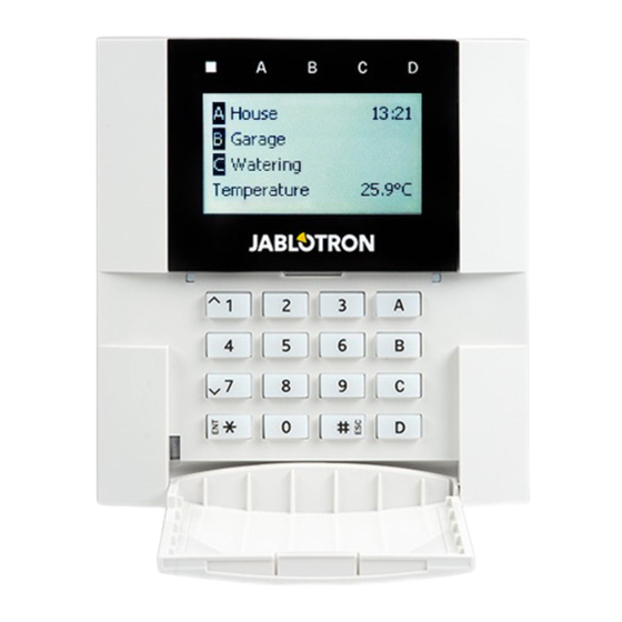
JA-14K(R) Security System Control Panel
A control panel is a fundamental part of the JA-10 series alarm system and is designed to protect small,
medium or large premises and it offers a lot of parameters and also the system profiles compliy with security
grade 2 requirements.
The control panel has BUS and/or wireless device (when the control panel is equipped with a radio module)
compatibility. It is recommended that only JA-10 devices are used with the system. Proper functionality cannot
be guaranteed when using third party devices.
Caution: The JA-10 security system can only be installed by a trained technician with a valid certificate issued
by an authorized distributor.
The manual is intended for trained technicians and is valid for control panel firmware LJ60422 and
N-Link configuration software 2.0.0 or higher.
Advertisement
Table of Contents

Related Manuals for jablotron JA-14KR


Summarization of Contents
1 Basic description and definitions
1.1 Basic system configuration requirements
Requirements for system setup and compliance with norms.
1.2 Access codes and their default settings
Defines default access codes and security settings.
1.3 Regular system check (maintenance)
Schedule for regular testing and maintenance of system components.
2 System size
2.1 Configuration and splitting
Details on how the system can be divided into sections.
2.2 System control
Describes how the system is controlled via keypads.
3 The JA-14K(R) control panel utility parameters
3.1 Description of JA-14K(R) control panel
Overview of the control panel's capabilities and connectivity.
3.2 Indication LEDs on the control panel board
Explains the function and meaning of LEDs on the control panel.
3.3 Additional connectors on the control panel PCB
Describes extra connectors for modules and tamper contacts.
3.4 Connection terminals on the control panel PCB
Details on how to connect power and BUS devices to terminals.
4 Before system installation
5 Installation of BUS devices
Procedure for connecting BUS devices to the system.
5 Installation of BUS devices
5.1 JA-10 BUS
Describes the JA-10 BUS system structure and wiring.
5.2 BUS cables
Information on the type and specifications of BUS cables used.
5.3 BUS branching and splitting
Rules and limitations for branching and extending the BUS cable.
5.4 Example of calculation of BUS consumption to back-up the system
Demonstrates calculating total BUS device consumption for backup power.
5.5 Power supply requirements
Requirements for backup battery capacity and charging for security grade 2.
6 Use of wireless devices
6.1 Installation of a JA-111R radio module
Instructions for installing the radio module for wireless communication.
6.2 Installation of wireless devices – enrollment mode
Process for enrolling wireless devices into the system using N-Link.
8 System configuration
8.1 The system profiles
Explains how system profiles pre-set parameters for compliance and behaviour.
8.2 Control panel operation modes
Describes the different modes the control panel can operate in.
8.3 Authorisation of users
Details user roles, permissions, and authorization levels within the system.
8.4 System optional parameters (N-Link – Parameters tab)
Configuration options available through the N-Link software's Parameters tab.
8.5 Types of alarms
Details different alarm types and their indications.
9 System control options
9.1 Way of authorization
Explains how the system verifies user authorization for operations.
9.2 System control by keypad
How to control and monitor the system using a system keypad.
9.3 System control by remote control
Using remote controls for system setting and PG output control.
9.4 System control by a calendar
Automating system control actions based on a pre-set schedule.
9.5 System control via application for smart phones
Controlling the security system using a dedicated mobile application.
9.6 System control via supplementary communicator voice menu (GSM / PSTN)
Remotely controlling the system using voice commands via phone.
9.7 SMS commands
Using SMS commands for system control and status queries.
9.8 Controlling the system via N-Link
System control and status overview using the N-Link software.
9.9 Control by Duress access control
Enables silent panic alarm triggered by a specific code under duress.
9.10 Obstacles preventing setting the system
Reasons that may prevent the system from being set.
9.11 Unsuccessful setting
Function for detecting and reporting failed system setting attempts.
9.12 Overview table of Groups of Events reported to users
Categorization of system events for reporting to users via SMS/calls.
9.13 System acoustic indication
Overview of acoustic signals used by the system for status indication.
9.14 Disabling and blocking options
Functions to temporarily disable or block devices or sections.
9.14.1 Disabling
Methods to disable inputs or entire devices.
9.14.2 Blocking
How sections can be temporarily bypassed during setting.
9.15 Non-alarm functions – Functions of PG outputs
Controlling system functions and PG outputs for automation.
10 Setting the system through N-Link SW
10.1 Starting the N-Link software and setting the system size
Initial steps for connecting and setting up the N-Link software and system.
10.2 Sections tab
Configuring parameters for independently monitored sections (zones).
10.3 Devices tab
Enrolling devices and setting their parameters within the system.
10.4 Users tab
Establishing new users and defining their system access rights.
10.5 PG outputs tab
Setting functions and links for programmable outputs (PG outputs).
10.5.1 Map of PG output activation
Defining what actions trigger a PG output.
10.6 Users reports tab
Configuring user reports for events via SMS or voice calls.
10.7 Parameters tab
Setting various system parameters and selectable functions.
10.8 Diagnostics tab
Checking and verifying the status of devices and their properties.
10.9 Calendars tab
Setting time schedules for automatic system events.
10.10 Communication tab
Configuring communicator behaviour and communication methods.
10.10.1 JA-190Y Settings
Setting parameters for the GSM communicator.
10.10.2 LAN Settings
Configuring the LAN communicator settings.
10.10.3 PSTN Settings (JA-190X)
Setting parameters for the PSTN communicator.
10.11 ARC tab
Setting communication parameters for Alarm Receiving Centres (ARCs).
10.11.1 Requrements for the setup of transmission paths to an ARC
Parameters for setting up transmission paths to ARCs according to standards.
10.11.2 Transmission paths
Details on GSM/GPRS and LAN communication protocols.
10.11.3 JA-10 CID and SIA codes
Lists CID and SIA codes for event reporting.
10.11.4 Setting the transmission of photos to external storage
Automatic settings for photo transmission upon registration.
11 Other N-Link options
11.1 System control by N-Link
Controlling system sections and status via N-Link software.
11.2 Event history
Accessing and viewing system event logs stored on the memory card.
11.3 System settings
Setting system behaviour for devices, sections, users, and communicators.
11.4 RF Signal
Visualizing radio band interference and signal quality.
11.5 Service
Switching between modes for system changes.
11.6 Refresh
Updating internal device settings after hardware changes.
11.7 Online
Managing N-Link connection status via USB.
11.8 Internet
Managing remote N-Link connection via the Internet.
11.9 Installation information
Recording installation company and system details.
11.10 Firmware update
Updating firmware on control panel and connected devices.
13 Firmware updates
13.1 General firmware update rules (FW)
General procedures and rules for updating firmware.
13.2 FW updates for the control panel and devices connected to the BUS
Updating firmware for control panel and BUS-connected devices.
13.3 FW updates for wireless devices using a USB cable
Updating wireless device firmware via USB cable.
13.4 Check after a FW check
Verifying system and device settings after firmware updates.
13.5 Info window
Displays a comprehensive overview of system technical data.
14 Supplementary information
14.1 Overview table of current consumption of BUS devices
Table showing current consumption of BUS devices in different modes.
14.2 Control panel currents overview
Table showing current consumption of the control panel and its modules.
14.3 Control panels dimensions
Physical dimensions of the control panel unit.
Need help?
Do you have a question about the JA-14KR and is the answer not in the manual?
Questions and answers