Table of Contents
Advertisement
Advertisement
Table of Contents

Related Manuals for MB Connect Line mbNET Series


Summary of Contents for MB Connect Line mbNET Series
- Page 1 MANUAL V5.1.6 MDH800 – MDH859 June 4 , 2019 MDH800, MDH802, MDH803, MDH804, MDH810, MDH811, MDH812, MDH813, MDH814, MDH815, MDH816, MDH817, MDH818, MDH819, MDH830, MDH831, MDH832, MDH832, MDH833, MDH834, MDH835, MDH841, MDH848, MDH849, MDH850, MDH855, MDH858, MDH859...
- Page 2 No part of this document and its contents may be reproduced, used or distributed without the express permission of MB Connect Line GmbH. Damages will be claimed in the event of infringement. All rights reserved. By purchasing the mbNET router, you have chosen a product made in Germany.
-
Page 3: Table Of Contents
Table of contents Table of contents ..............................3 Gerneral .................................. 8 Purpose of this documentation ..........................8 Validity of this documentation ..........................8 Brief description ..............................8 Features .................................. 8 Prerequisites/components: ............................. 8 Releas notes: ................................9 Safety Instructions (English and France) ......................10 Using Open Source Software .......................... - Page 4 Configuration screen of the mbNET ........................35 12. Basic configuration of the router using the web interface ................36 Web interface home page ............................. 36 Icons, buttons and fields ............................37 System > CTM (Configuration Transfer Manager) ....................38 System > Settings..............................39 System >...
- Page 5 Root certificate key usage ..........................90 Creating a client certificate ..........................91 Client certificate source ........................... 92 Client certificate subject ..........................93 Client certificate – Extensions .......................... 94 Client certificate – Key usage ........................... 95 Client certificate – Netscape ..........................96 Generating CRL-Files (Certificate Revocation Lists) ....................
- Page 6 Settings for Simatic Manager ..........................142 Enabling RFC1006 on the mbNET ......................... 142 Settings for NETPro Step 7 ..........................143 Create subnets ..............................143 Add PC station ..............................144 Configure PC station ............................145 Add PC/PG station .............................. 146 Configure mbNET PC station ..........................149 Routing ................................
- Page 7 Diagnostic ................................201 22. Alarm management ............................202 General ................................202 Digital inputs ............................... 202 Multiplex inputs ..............................203 Digital outputs ..............................205 23. Status messages ............................... 207 General ................................207 Status – Interfaces ............................... 207 Status - Network ..............................208 Firewall ................................
-
Page 8: Gerneral
Gerneral Purpose of this documentation This user manual describes the functions and use of the mbNET router MDH800 – MDH859. Please read carefully and retain this information. Validity of this documentation This manual is valid for the router mbNET MDH800, MDH802, MDH803, MDH804, MDH810, MDH811, MDH812, MDH813, MDH814, MDH815, MDH816, MDH817, MDH818, MDH819, MDH830, MDH831, MDH832, MDH832, MDH833, MDH834, MDH835, MDH841, MDH848, MDH849, MDH850, MDH855, MDH858, MDH859 from firmware version V 5.1.6... -
Page 9: Releas Notes
Releas notes: Version Date V 5.0 01.10.2017 Comment Previous version: V 3.3.5 DR 05 (23.03.2017) Changes: Chapter 11.1.4 Cloudserver Here, for the purpose of hardening the system, the verification via certificates was additionally added. Chapter 12.4 System > Settings > Time Settings The following functions have been added: ... -
Page 10: Safety Instructions (English And France)
Version Date Comment V 5.0 DR01 18. 07. 2018 Chapter 25. Firmware update directly via USB: Additional information. V 5.0 DR01-1 13. 12. 2018 Chapter 25. Firmware update directly via USB: error correction “…until LED FC3 flashes…” is wrong, it has to be Fc2. In chapter 19.1 Security >... - Page 11 Consignes de sécurité Le routeur est construit selon l’état actuel de la technique et les règles techniques reconnues en ma- tière de sécurité (voir la déclaration de conformité). Le routeur doit être monté à un endroit sec. Aucun liquide ne doit pénétrer dans le routeur, car cela pourrait occasionner des chocs électriques ou des courts-circuits.
-
Page 12: Using Open Source Software
€ 10,00. Our offer to send the source code upon request ceases automatically 3 years after delivery of our product to the customer. Requests must be directed to the following address, if possible under specification of the serial number: MB connect line GmbH Fernwartungssysteme Winnettener Str. 6 91550 Dinkelsbühl... -
Page 13: Technical Specification
Technical specification Dimensional drawing Page 13 of 237 Version: 5.1.6 – June 4 , 2018... -
Page 14: Datasheet
Datasheet General data 10 – 30V DC (external Power Supply or other SELV Power Supply Source, Voltage V (DC) rated 10-30V DC, max. 40A) Power consumption max. 1300 mA @ 24 V IP protection class IP 20 Area of application Dry environments 0 –... - Page 15 Optional interfaces 10/100 Mbit/s full and half duplex operation, autodetection patch cable / crossover WAN interface cable Interface 1 (COM1) RS-232/485 (using software switchable) Interface 2 (COM2) RS-232/485 (using software switchable) or MPI/PROFIBUS - 12 Mbit/s depending on the device SIM card slots 2 pcs.
-
Page 16: General Approvals
Communication 2100 (B1), 1900 (B2), AWS (B4), 850 (B5), 900 (B8) MHz HSxPA CDMA EVDO/1x: BCO, BC1, BC10; downlink max. 42 Mbps, uplink max. 5.76 Mbps 1900 (B2), AWS (B4), 850 (B5), 700 (B13), 700 (B17), 1900 (B25) MHz; down- link max. -
Page 17: What Is Included In The Package
GSM antenna (SMA male) Router variants with WiFi modem Wifi / Bluetooth antenna (2.5 m cable length) (SMA female) Should any of these parts are missing or damaged, please contact the following address: MB connect line GmbH Winnettener Str. 6 91550 Dinkelsbühl GERMANY Tel.: +49 (0)9851/282529-0... -
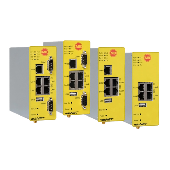
Page 18: Displays, Controls And Connections
Displays, controls and connections Front panel view Label Status Description LED off Serial interface COM1 not receiving data. (Function 1) LED on Serial interface COM1 receiving data. LED off Serial interface COM1 not sending data. (Function 2) LED flashing Serial interface COM1 sending data. LED off Serial interface COM2 not receiving data. -
Page 19: Top, Bottom And Back Panel Views
Top, bottom and back panel views Top view Power supply connection 10-30V DC 0V DC connection Digital input I4 (10-30V) Digital input I3 (10-30V) Digital input I2 (10-30V) Digital input I1 (10-30V) Fuse-protection 10-30V DC 0V DC connection Digital output A2 Digital output A1 Bottom view MDH814, MDH819, MDH834, MDH849,... -
Page 20: Interfaces
Interfaces Pinout of top panel terminal blocks X1 and X2 Power supply connection 10 – 30V DC 0V DC connection Digital input I1 (10 – 30V) Digital input I2 (10 – 30V) Digital input I3 (10 – 30V) Digital input I4 (10 – 30V) Fuse protection 10 –... -
Page 21: Pinout Of Front Panel Lan / Wan Ports
Pinout of front panel LAN / WAN ports Signal 1 2 3 4 5 6 7 8 Not connected Not connected Pinout front panel USB port Signal VCC (+5V) - Data +Data Page 21 of 237 Version: 5.1.6 – June 4 , 2018... -
Page 22: First Time Operation
First time operation Router installation Mounting position / minimum distances The mbNET router is designed for mounting on DIN rails (in accord- ance with DIN EN 50 022) and is intended for switchgear installation. Installation and mounting must be carried out in accordance with VDE 0100 / IEC 364. -
Page 23: Connecting The Router To The Power Supply And Switching On
Connecting the router to the power supply and switching on ADVICE Before connecting the router to a network or PC, first ensure that it is properly connected to a power supply, other- wise it may cause damage to other equipment. You should therefore follow the instructions given below IMPORTANT Connect equipotential bonding to the grounding lug on the router’s top panel! ... -
Page 24: Connecting The Router To A Configuration Pc
Connecting the router to a configuration PC Before configuring the router, connect it to the computer using the crossover cable supplied (1). To do this, connect one end of the ca- ble to the router port labeled LAN, and the other end to your com- puter’s network card. -
Page 25: How To Set Computer Address (Ip Address) And Subnet Mask In Windows 7
How to set computer address (IP address) and subnet mask in Windows 7 To set the IP address, proceed as follows: First, select “Start” (1) then Control Panel from the Windows Start menu (2) and then click on Network Con- nections (3). -
Page 26: How To Set Computer Address (Ip Address) And Subnet Mask In Xp
How to set computer address (IP address) and subnet mask in XP To set the IP address, proceed as follows: First, select Control Panel from the Windows Start menu (1) and then double-click on Network Connections (2). Right-click on Local Area Connec- tion (3) and select Properties. -
Page 27: Access The Web Interface Of The Router
Access the web interface of the router Proceed as follows: Open your browser and enter the router’s IP address in the address bar: The factory setting is: 192.168.0.100 Log into the router using the following login data: □ Username: admin □... -
Page 28: Cloudserver
Cloudserver If you selected “Cloudserver“, you can synchronize your configurations per CTM to your device. The following page will appear. Page 28 of 237 Version: 5.1.6 – June 4 , 2019... -
Page 29: External Router
External Router If you selected External Router, you will be redirected to the WAN-Settings. Label Description WAN Typ DHCP: The router obtains his connection information like the IP address and the subnetmask via DHCP (Dynamic Host Control Protocol). The router will obtain connection information such as IP address and sub- net mask using DHCP. -
Page 30: External Dsl Modem
External DSL Modem If you selected DSL-Modem then you will be redirected to PPP-Settings. Label Description PPP Type PPPoE: Activate Point-to-Point Protocol over Ethernet. Used Protocol for connections over ADSL. PPTP: Activate Point-to-Point Tunneling Protocol. Protocol used for a transmission method with tunneling. User / Password Please enter your username and the password for your Point-to-Point Connection. -
Page 31: Wlan
WLAN If you have selected „WLAN“, you will see this screen. Label Description WLAN type DHCP: The router obtains his connection information like the IP address and the subnet- mask via DHCP (Dynamic Host Control Protocol). The router will obtain connection information such as IP address and subnet mask using DHCP. -
Page 32: Cloudserver
Cloudserver Label Description You can choose between: Europe USA/Canada Cloudserverlist rsp.mbconnect24.net (EU) rsp.mbconnect24.us (US/CAN) User Defined Cloudserver address/name The Cloudserver to be used is displayed / entered here. If you have set a session key on the upload of the configuration file, then Session-Key you have to enter this session key here. -
Page 33: Start Screen Of The Mbnet
Start screen of the mbNET If you search for your mbNET in your web browser you get this screen. Here you can see the connection or network- problems of the mbNET. To see more detailed information click on the “I”. Click on “Setup”... -
Page 34: Classic Router
Classic router If you selected this option then you will be directed to the following page. A wizard appears which helps you to con- figure your mbNET router. If you have selected “Classic router” a connection wizard will launch, simplifying network, Internet and VPN connec- tion set up. -
Page 35: Configuration Screen Of The Mbnet
Configuration screen of the mbNET On successful log in you will be taken to the configuration interface home page. Page 35 of 237 Version: 5.1.6 – June 4 , 2018... -
Page 36: Basic Configuration Of The Router Using The Web Interface
Basic configuration of the router using the web interface Web interface home page The home page is designed to provide you with an at-a-glance view of the most important information on mbNET router access or status. The side (1) and top (2) navigation bars will pro- vide the support you need when con- figuring the router. -
Page 37: Icons, Buttons And Fields
Icons, buttons and fields In the rest of these operating instructions you will repeatedly encounter specific icons. These are listed and explained on the next page. Icon and field Description types Gray LED: connection inactive / cable or USB device disconnected. / Green LED: connection active / cable or USB device connected. -
Page 38: System > Ctm (Configuration Transfer Manager)
System > CTM (Configuration Transfer Manager) The CTM allows the transmitting of the configuration via internet connection, or respectively the device receives his configuration as soon as it gets online. CTM has to be activated on the device, to ensure the transmitting of the con- figuration. -
Page 39: System > Settings
System > Settings Before you configure the mbNET industrial router specifically for your application, you should first make certain basic settings. To do this, proceed as follows: On the navigation bar at the top bar on the web interface home page, click System and Settings. - Page 40 Mail Settings Selection field (yes / no) for activating / deactivating the automatic mail settings. If you select "yes", the router uses the MB connect line mail server with fixed specifi- Activate automatic Mail cations.
-
Page 41: System > Web
SMTP requires The box should be checked or unchecked depending on ISP. Ask your ISP for the Authentification correct setting. A user name and password are required for SMTP server authentication, i.e. if the User router wants to send an email to the SMTP, it must first authenticate itself if neces- Password sary. - Page 42 Checkbox for activating / deactivating this function. Disable complete Web-GUI (only If the function is activated, the web server of the mbNET is completely recoverable with Factory Reset!) switched off. That is, the web interface of the mbNET is no longer accessible via the web. Checkbox for activating / deactivating this function.
-
Page 43: Wlan Configuration
WLAN Configuration Network > WLAN Interface Interface Type: DHCP: Settings are received with DHCP. Static IP: You can set the settings manually. Page 43 of 237 Version: 5.1.6 – June 4 , 2018... - Page 44 Settings SSID Define your SSID. Authentification OPEN Mode At this authentication method, every mobile Station is able to connect with the Access Point if the SSID matches. Some wireless clients know the option ALL or ANY, which allows to make a connection with every access point independently of the SSID.
- Page 45 Operating Band Select the operating band defined under IEEE 802.11 standard. Operating Band Legacy 11 B only This is the oldest standard for radio networks. If your WLAN-adapter supports newer stand- ards like 802.11g, then you should use them instead. ...
-
Page 46: Description Of Different Connection Scenarios
Description of different connection scenarios General Now that you have completed basic configuration of the router (see previous pages), it needs to be connected via the appropriate connection type, and configured using the web interface. A description of some basic connection scenarios follows. Choose the connection scenario that best applies to you and follow the instructions in the relevant sec- tion. - Page 47 Configuring the mbNET router for connection with a client PC via DSL Internet access, using a DSL modem (see section 9.4) Configuring the mbNET industrial router for connection to the Internet using another router (see section 9.5) Configuring the mbNET industrial router for VPN connection with a client (client – router) (see section 9.6) Page 47 of 237...
-
Page 48: Configuring The Industrial Router For Connection Over The Telephone Network
Configuring an mbNET industrial router for VPN connection to another mbNET router (router – router) (see section 9.7) Configuring the industrial router for connection over the telephone network The following diagram shows how to connect the industrial router to a client over the public telephone network. -
Page 49: Connecting And Configuring The Router
Connecting and configuring the router Before you begin: The router should be connected to a suitable power source, and the Power and Ready LEDs should be solid green. Connecting the router Analog connection (applies to device models MDH xx0) ... -
Page 50: Configuring The Router Using The Web Interface
Configuring the router using the web interface – Modem. On the web interface home page, click on Network Note: Not possible at mbNET variant with WLAN (FW 4.1). Configuring the router – client connection over the telephone network Network – Modem For more detailed information, please see section Label Description... - Page 51 SIM PIN If required, you can enter the SIM card PIN here. However, the device will also work ( GSM only ) without SIM card PIN protection Provider You can select your mobile broadband provider here. If it does not appear, select “Other”...
- Page 52 Label Description Internet connection Select either Internet via modem or Internet via WAN. Save your changes by clicking Save Changes Click on – System User and add a user with dial- in rights. For further notes on adding us- ers and assigning specific rights, please see section Adding users...
-
Page 53: Configuring A Client (Pc) To Access The Router
Configuring the router – client connection over the telephone network (continued) Configuring a client (PC) to access the router You can connect directly to the router, and to a re- mote network, using a telephone line. Router ac- cess must first be correctly configured as de- scribed above. - Page 54 Configuring the router – client connection over the telephone network (continued) Now you need to give your connection a name, then click NEXT. Enter the telephone number of your remote station (the number that accesses the indus- trial router) ...
-
Page 55: Establishing A Connection Between The Client Pc And The Industrial Router
Configuring the router – client connection over the telephone network (continued) Establishing a connection between the client PC and the industrial router Double-click on the connection that you created using the in- structions in the previous section. In this window, enter the user name and password that you created previously when configuring the modem. -
Page 56: Configuring The Industrial Router For Connection Via The Internet
Configuring the industrial router for connection via the Internet The following diagram shows how to connect the industrial router to a client computer via the Internet. The client is a computer with a modem connection. 77.180.121.116 123.456.789.21 Connection and configuration of the router Before you start make sure that the router is connected to a suitable power source and he Power and Ready LEDs are shining solid green. -
Page 57: Configuring The Router - Client Connection Over The Telephone Network
Configuring the router – client connection over the telephone network On the web interface home page, click – Network Modem and then click the Outgoing SIM1 tab when a SIM card is in the SIM card Slot1. The following screen is displayed. Follow the descriptions on the following pages. - Page 58 – settings, please see section Network – Modem For a detailed description of the Network Modem Label Description ANALOG: If using an analog device, enter the command +GCI=country code (for country codes, see Country codes for analog devices) here, and in the second row, the command X3 (do not wait for dial tone).
- Page 59 Please Note: The internet-by-Call providers are changing their prices often. MB connect line cannot be made responsible for any price changes. Now click on – Network Internet and enter the following settings. Internet Connections Internet Connections Label Description The Failover feature allows you to switch between different Internet connec- Failover tions.
- Page 60 Internet Settings Internet Settings Label Description Select “keep connection” here. Connection Mode Using the drop-down field you can decide whether the Internet connection lock connection by should be closed when one of the inputs receives a signal (internally-gener- ated, between 10 and 30V). Enable this setting.
- Page 61 Internet Settings > Settings Internet Settings > Settings Connect on traffic Activate the checkbox if a connection to the Internet, initiated by data packets sent, is to be established. Ignore traffic on LAN If this check box is activated, no connection that differs from the setting under "Con- nection Mode"...
-
Page 62: Router Internet Dial-In
Configuring for connection over the Internet (continued) Router Internet dial-in In the screen shown above, the router is configured to establish an Internet connection as soon as it is restarted Network – Internet For other methods of Internet dial-in, please see section ... -
Page 63: Configuring The Industrial Router For Connection To The Internet Using A Dsl Modem
Configuring the industrial router for connection to the Internet using a DSL modem The picture below shows how to connect the mbNET industrial router to a client PC over the Internet, using a DSL modem. The client needs to use an existing Internet connection, or to set one up. 123.456.789.21 77.180.121.116 Connecting and configuring the router... -
Page 64: Configuring The Router Using The Web Interface
You can also choose whether the mbNET should send you an email, use a dynamic DNS service, or be accessible over the Internet via MB Connect Line’s DynDNS. Confirm and save your entries. Finally, the mbNET must be restarted to fully implement the settings. - Page 65 Configuring for connection over the Internet (continued) – From the web interface home page, click Network Internet The following site should be displayed. – settings, please see section “Network – Internet” For a detailed description of the Network Internet Label Description...
-
Page 66: Establishing A Connection Between Client Pc And Router
As the router IP address changes each time it dials up to the Internet, a helpful alternative is to use our DynDNS service. For information on setting up and using the MB Connect Line DynDNS service, Network – DynDNS please see section Displaying connection status –... -
Page 67: Configuring The Industrial Router For Connection To The Internet Via An Existing Router
Configuring the industrial router for connection to the Internet via an existing router The diagram below shows how to link the industrial router up to a network which already has a router that is set up for connection to the Internet. The existing router must first be assigned the right settings. This mbNET operating mode is particularly useful if you need to set up a connection between the industrial... - Page 68 Configuring the router for connection to the Internet via an existing router – settings, please see section “Network – WAN” For a detailed description of the Network Label Description As in the example shown, select Static IP. Interface Type This setting also requires a DNS server (see Network – DNS server). WAN IP Here, enter the IP address of the mbNET connected to the WAN port.
- Page 69 Configuring the router for connection to the Internet via an existing router On the web interface home page, click on – Internet. Network The following screen will be displayed. Follow the instructions on the subsequent pages. – settings, please see section “Network – Internet” For a detailed description of the Network Internet...
- Page 70 After applying the changes, please restart the router. Page 70 of 237 Version: 5.1.6 – June 4 , 2019...
-
Page 71: Configuring The Industrial Router For Vpn Connection To A Client
Configuring the industrial router for VPN connection to a client Setting up a virtual network reduces the cost of a fixed connection between two or more LANs and ensures se- cure data transfer over the non-secure Internet. Using a tunneling protocol sets up a secure connection called a VPN tunnel. -
Page 72: Connecting And Configuring The Router
Configuring the router for VPN connection to a client Connecting and configuring the router Connecting the router A VPN connection first requires that the router has an Internet connection in place. For instructions on how to configure the router for connection to the Internet, you can refer to the connection scenarios already described above, based on the connection mode required. - Page 73 Connection-Wizard 13.6.1.3.1 The connection wizard helps you to configure your connections quickly and easily. To launch the wizard, click on the Wizards link at the top right of your browser. If you have disabled the autolaunch function for wizards, click on the Start button for the VPN connection wizard.
- Page 74 Label Description Enable To enable the connection, check the box by clicking on it. If you select “yes” here, the PPTP server will be configured using the mbNET’s LAN ad- Auto config dress. This setting needs to be tried out first. You should only enter your PPTP server set- tings manually if there is an address conflict.
-
Page 75: Configuring A Client Pc For A Vpn Connection To The Router
Setting up the router for a VPN connection (continued) Configuring a client PC for a VPN connection to the router To proceed with set up, the client PC must have an existing Internet connection. For information on setting up a client PC please see section Configuring a client (PC) for router access ... - Page 76 Note: The example in Figure 86 uses an IP address assigned by the ISP. For information on setting up and using the MB Connect Line DynDNS service, please see Network – DynDNS section When entering the router’s IP address, make sure that you always enter the current IP address (the IP ad- dress changes every time the router connects to the Internet).
-
Page 77: Setting Up A Vpn Connection Between Client Pc And Router
Setting up the router for a VPN connection (continued) Setting up a VPN connection between client PC and router Router Internet dial-in Depending on the connection mode, the router must be configured for Internet access, connected to the Internet, and accessible via the IP address. Setting up a VPN connection from client to router ... -
Page 78: Configuring A Connection Between Two Routers Via Vpn Pptp
Setting up the router for a VPN connection (continued) The client PC will display a flashing screen icon the router is connected. You can display the connection properties by right-clicking on the icon On a PC connected to the router, clicking Status on the sidebar and VPN-PPTP... -
Page 79: Settings For Connecting Two Industrial Routers - Pptp - Server
Settings for connecting two industrial routers – PPTP – server □ From the home page navigation bar on the left, click and on the navigation bar at the top click PPTP. □ This will display the screen below. If you now set the “Enable” box and save this setting, your server is live. It will then provide dial-in clients with addresses from its local network and use its LAN address as the PPTP server address. - Page 80 Label Description Enable To enable the connection, check the box by clicking on it. Selecting “yes” means that the mbNET’s local network range and IP address will be used. Autoconfig By selecting „no“, you can enter this information manually. Local IP address or This is the PPTP server address Range Remote IP address or...
-
Page 81: Settings For Connecting Two Industrial Routers - Pptp-Client
Settings for connecting two industrial routers - PPTP-Client Clicking on the green plus sign on the far right will open the following configuration screen. □ Name: Enter a name of your choice for the connection. □ Host Name or IP: Enter the public address or DynDNS name for the PPTP server. - Page 82 Enable To enable the connection, check the box by clicking on it. Assign a name to the client. Name In the example we used: PPTPclientConnection Here, enter the name or IP address that the client uses to contact the server. In the exam- Host name or IP ple, this is: 123456789@mbNET.mymbnet.biz...
-
Page 83: Creating Certificates And Revocation Lists Using Xca
Creating certificates and revocation lists using XCA. Certificates overview Any subscriber communicating over a VPN connection needs 2 certificates. One certificate must be signed by a CA (Certificate Authority). Each subscriber must have the CA certificate plus a “server” or “client” certificate. In our case: ... -
Page 84: Creating Certificates
Creating certificates Christian Hohnstädt’s XCA freeware program is useful for creating certificates. Using this program makes it easy to create X.509 certificates as well as the necessary private keys. You can download the program from http://sourceforge.net/projects/xca free of charge, and install it in Windows in the usual way (run the .exe file). -
Page 85: Creating A Root Certificate
Creating a root certificate To create a root certificate, click on the “Certificates” tab and open the following dialog box by clicking “New Certificate”. Root certificate source First, change the Signature algorithm to MD5 so that the certificate is compatible with the mbNET. Then you can go straight to the “Subject”... -
Page 86: Root Certificate Subject
Root certificate subject In the “Subject” tab, fill in the fields from “Internal Name” through “email address”. For VPNs using IPSec, Subject settings can later be used as an ID (cf. section Authentication) Next, create a private key by clicking on “Generate a new key”. Please do not use accents (e.g. - Page 87 Select key type RSA. You can select any key size and of course, any name. The longer the key, the more secure the encryption but also the more processing power required. Page 87 of 237 Version: 5.1.6 – June 4 , 2018...
-
Page 88: Root Certificate Extensions
Root certificate extensions In the “Extensions” tab you will find the settings for certificate type and validity. Basic constraints Type = Certificate Authority (CA) Check the box labeled Critical and Key identifier Check the box labeled Subject Key Identifier Validity You can enter a specific start and end date in the relevant fields or use the adjacent Time Range field. - Page 89 Subject alternative name The subject alternative name is a list of alternative names for the certificate holder. These can be RFC822 names (email), DNS names, X.400 addresses, EDI names, URIs or IP addresses. In principle, any structured naming system is applicable. If using PKIX, this extension is essential when the certificate subject field is empty. Issuer alternative name For issuer alternative names, the same applies as for subject alternative names.
-
Page 90: Root Certificate Key Usage
Root certificate key usage In the “Key usage” tab you will find key usage and extended key usage options. Neither key should be critical i.e. you should leave the boxes marked Critical unchecked. To create a root certificate, please select the following values in the left hand column: ... -
Page 91: Creating A Client Certificate
Creating a client certificate To create a certificate signed by this CA, in the “Certificates” tab, highlight the root certificate that you just cre- ated, and click again on “New Certificate”. After this, the following dialog appears. Page 91 of 237 Version: 5.1.6 –... -
Page 92: Client Certificate Source
Client certificate source First we need to select our root certificate as the one that will be used as signatory. We also need to set the signature algorithm to MD5 again. We see here that our root certificate is already set as the one to use as signatory. Page 92 of 237 Version: 5.1.6 –... -
Page 93: Client Certificate Subject
Client certificate subject Once again, assign the client certificate details, from internal name through email address. Then generate a key for the client certificate. It is recommended that the key should be the same size as the one for the root certificate. Page 93 of 237 Version: 5.1.6 –... -
Page 94: Client Certificate - Extensions
Client certificate – Extensions As your client certificate does not need to sign any other certificate, select End Entity as the Certificate Type. Basic constraints Type = End Entity Key identifier Check the box labeled Subject Key Identifier Validity You can enter a specific start and end date in the relevant fields or use the adjacent Time Range field. Time Range In the dialog boxes to the right, enter the number of days, months or years. -
Page 95: Client Certificate - Key Usage
Subject alternative name The subject alternative name is a list of alternative names for the certificate holder. These can be RFC822 names (email), DNS names, X.400 addresses, EDI names, URIs or IP addresses. In principle, any structured naming system is applicable. If using PKIX, this extension is essential when the certificate subject field is empty. Issuer alternative name For issuer alternative names, the same applies as for subject alternative names. -
Page 96: Client Certificate - Netscape
Client certificate – Netscape If you would like additional security, you can also select the SSL Server or SSL client option for your VPN subscribers according to their role (client or server). The advantage of this is that OpenVPN can query whether a VPN server is also equipped with SSL. This option can also be enabled on the mbNET. - Page 97 Now the certificates need to be published by highlighting the relevant ones in the “Certificates” tab and then clicking “Export”. In the menu below, you can specify the save location for the certificate on your computer, and also the file format.
-
Page 98: Generating Crl-Files (Certificate Revocation Lists)
As your client is to be authenticated by the client certificate, it also needs the private key for this certificate. As shown in Figure 112, export the client certificate using export format PKCS #12 with Certificate chain. When you click OK, the client certificate will save to the location that you specified above. - Page 99 To export, proceed as follows: In the “Revocation lists” tab you now see the revocation list that you just created. Highlight it, and click “Export”. Select .pem as the export format. Choose a suitable save location, then confirm with OK. You can now import the list System ...
-
Page 100: Importing Certificates In Windows Xp
Importing certificates in Windows XP To import finished certificates, you need to set up what is known as a Certificate Management Console. To do this, click “Start” -> “Run” and type in “MMC”. Then click on “File – Add/Remove Snap-in” and in the next screen, select “Add”. - Page 101 Double-clicking on the relevant certificate displays its properties. In the “General” tab you can check, amongst other things, which CA issued the certificate, how long it is valid for and whether you have a private key for it. This is very important when using certificates for web server publishing. There is more information about the issued certificate in the "Details"...
-
Page 102: System Settings
System settings The most important system settings have already been outlined above in System Settings. A more detailed explanation of additional system settings is given below. System – Users General With user management you can: Give users access rights to web interface administration, and modem or VPN dial-in. ... -
Page 103: Adding Users
Adding users To add a user, proceed as follows: In the navigation bar on the left, select System and then Users. In the first row of input fields, enter the username, password and full name of the user. Please note: All three fields must be completed otherwise you will receive an er- ror message when you save. -
Page 104: Deleting Users
Deleting Users To delete a user, proceed as follows: In the navigation bar on the left, select System and then Users. Select the row that contains the user name, password and so on, and click the icon to Delete To apply the settings to the router perma- nently, click Apply Changes You will now no longer be able to log in or authenticate this user via the web interface,... -
Page 105: System - Certificates
System – Certificates A key component of VPN connections with IPSec or OpenVPN is the trust relationships between two or more com- munications peers. Authentication settings are made during configuration, as explained in the section Authentica- tion. For secure communication, authenticity needs to be verified. Certificates help to ensure also that the right peers are communicating with each other. - Page 106 Label Description Choose PKCS12 file: certificate file selection (PKCS12 file). Browse: provides file path for certificate file. Name for this certificate (optional): optional entry of a name for the certificate file. Import new cer- Password: certificate password entry. The certificate must have been assigned a password tificates when it was created, otherwise it will not import.
-
Page 107: Root Certificate (Ca)
Root certificate (CA) A root certificate verifies whether the remote station certificate is also signed by the root certificate. If the authentication method in the VPN settings is set to “Authentication by certificate from CA”, this root certifi- cate must then be imported. The entry in the root certificate is used to confirm that the person dialing in has a valid certificate. -
Page 108: Peer Certificates (Ipsec)
Peer certificates (IPSec) Peer certificates are remote station certificates. They are only needed if “Authentication by peer certifi- cate” is selected in the VPN settings. In this situation the existence of a local copy of the certificate is con- firmation of its validity. The remote station certificate is selected via the relevant crt file and then imported. -
Page 109: Crl
The Certificate Revocation List (CRL) is used to verify whether or not the computers dialing in hold valid certificates. The CRL contains the serial numbers of certificates that should be blocked. So if you wish to withdraw someone’s dial-in access rights to the router or the PLC behind it, you just need to create a CRL. XCA makes this easy. -
Page 110: System - Usb
System - USB You can connect a USB device (flash or external drive) to the industrial router’s USB port. The USB storage medium can be accessed via SFTP. To set up the USB port, select System on the navigation bar on the left and on the navigation bar at the top. -
Page 111: System - Logging
System – Logging System logging for the mbNET can be outsourced to another computer by using a log server. Label Description Set debug output to syslog Output debug info to the syslog. Log also to USB-Device The logs are also being saved to an USB-Device. To enable a log server, place a check in the box by clicking on it. -
Page 112: System - Configuration
System – Configuration Using this menu, you can both backup and restore a system configuration. The configuration can be saved e.g. to a connected USB drive before making major changes, and if necessary, restored onto the industrial router. Label Description Backup Configuration Assign a meaningful name to the configuration. -
Page 113: System - Firmware
System – Firmware There are two ways to update the industrial router’s firmware; both are described on the following page. Upgrade via USB This requires a USB storage device to be connected to the industrial router so that the file can be transferred across. The firmware name (image.bis) is listed here. -
Page 114: Upgrade Via Network
Upgrade via Network In this case you need to enter the IP address of a TFTP server, and the firmware name. In this case: image.bin Before the upgrade can start, the “tftpd32” tool must be launched. You can download this free of charge at http://tftpd32.jounin.net/ Once you launch the tool, enter the following settings in the “DHCP server”... -
Page 115: Network
Network Network – LAN LAN configuration allows you to configure the router IP address (LAN address) and subnet mask. This is the IP address used for accessing the router from the LAN. Label Description Interface To set up the LAN interface, click on the tab. LAN IP address Enter the router IP address. -
Page 116: Network - Wan
Network – WAN The industrial router’s WAN interface can connect a local network with a remote network, or with a public network like the Internet. Therefore the WAN interface is configured according to how it will be used. Label Description You can select from the following interface types: DSL: Select this option if your router is directly connected to a DSL modem that connects to the In-... - Page 117 Network – WAN (continued) Label Description When selecting interface type, choosing DSL also requires you to select one of the following options: PPPoE: Select this option if your ISP requires a PPPoE (Point to Point Protocol over Ether- net) connection. A lot of modems are set to this option. The external IP address that a remote station uses to access the router is specified by the ISP.
-
Page 118: Network - Modem
Network – Modem Notice: Not valid for mbNET variants with WiFi Network – Modem –Incomming The industrial router’s integrated modem is for dial-in or Internet connection (analog, ISDN, GSM) where there is no available DSL or network connection. NOTE: If the modem is used for an outgoing Internet connection, it cannot be used for an incom- ing connection. - Page 119 Label Description Incoming You need to enable this option for the router to handle incoming dial-in or ISDN connections. You need to enable this function by checking the box so that a client computer can Dial-in enable access the router. You need to enter the router IP address here.
-
Page 120: Network - Modem - Outgoing
Network – Modem – Outgoing Following settings are relating to the outgoing connections of the modem. Label Description If you would like to call multiple terminals, set this option to “yes”. You will then see three more fields where you can enter numbers that will be selected on receipt of a signal at digital inputs 2 to 4. - Page 121 Authentication via Use the default setting for the authentication protocol. In principle this is preset when a dial-up connection is set up. Use the default setting for the authentication protocol. In principle this is preset when a Authentication via dial-up connection is set up. As a rule, CHAP is the process used by ISPs for Internet ac- CHAP cess log in via a modem or ISDN adapter.
-
Page 122: Menu Settings Sim
Menu Settings SIM First, we need to specify a primary SIM card, which will always be verified or used first. The sec- ondary SIM card is always the non-primary one. Switching is based on two (selectable) criteria: The SIM card fails to initialize, or to register on the cellphone network ... - Page 123 Switch to secondary SIM On / Off card if roaming is detected Switch to secondary SIM card when there is a fail- On / Off ure with the primary SIM card Remotely control services via SMS Enable Service Control via SMS On / Off Check the Phone Number of the Sender On / Off...
-
Page 124: Network - Modem - Callback
Network – Modem – Callback The settings below apply to the call back function. This function triggers Internet dial-in remotely via a telephone or dial-up connection. It must be set up so that the Internet connection will be established via WAN or modem. Note that call back does NOT work with UMTS-enabled devices. -
Page 125: Network - Modem - Sms
Network – Modem – SMS Label Description Enable Service Con- This function enables the use of service control via SMS trol via SMS Check the Phone This ensures that the mbNET only accepts SMS commands from a specific number. Then enter the sender’s cell number in “Senders Phone Number” in the next field. Com- Number of the Sender mands sent from any other number will now be rejected. -
Page 126: Remote Service Control Commands Using Sms
Remote service control commands using SMS INET START or INET STOP This controls the industrial router’s Internet connection. Note that you can only control an Internet connection that is active and has been established by the industrial router. IPSEC START [connection name] or IPSEC STOP [connection name] PPTP START [connection name] or PPTP STOP [connection name] OPENVPN START [connection name] or OPENVPN STOP [connection name]... -
Page 127: Network - Internet
Network – Internet Router Internet dial-in is dependent on connection type and on the appropriate configuration of specific settings. Network – Internet – Internet Connections Internetconnections Label Description Following options are available at the drop down menu: internet via WAN (external Router, fixed line) Select this Setting if he mbNET does not create the internet connection automatically. -
Page 128: Network - Internet - Internet Settings
Network – Internet – Internet Settings Internet Settings keep connection Select this setting if the router should try to connect to the Internet immediately after restarting or after pressing the RESET button on the front of the router. Important: with this setting, the connection will stay on ... - Page 129 Internet settings Settings The Settings tab is only displayed if Internet connection via WAN or modem has been selected along with on demand for the connection mode. The following settings options will be displayed: To connect to the Internet when a data packet is sent, check this box. In other words, an Internet connection will be established if the LAN is trying to contact a subscriber Connect on traffic outside of the LAN.
-
Page 130: Internet Failover Connection
Internet failover connection Firmware versions 3.x.x. and higher have an optional failover function for the Internet connection. Page 130 of 237 Version: 5.1.6 – June 4 , 2019... - Page 131 First you need to switch on this function. In the table below, you can select a priority order for the Internet interfaces. The order and number or interfaces are freely definable. The “Retry interface before switch to next interface” parameter specifies how many times an Internet connection should be allowed to fail before switching to the next interface.
- Page 132 In addition, routers with a GSM/UMTS module and double SIM slot can switch between SIM1 and SIM2. First, we need to specify a primary SIM card, which will always be verified or used by default. The secondary SIM card is always the non-primary one. Switching is based on two (selectable) criteria: ...
-
Page 133: Network - Dhcp
Network – DHCP You can configure the industrial router as a LAN or WAN DHCP server. DHCP enables you to integrate a new computer into an existing network without the need for any additional configuration. The only requirement is for the computer to be set up to acquire the IP address automatically. -
Page 134: Network - Dns Server
Network – DNS server DNS is used to resolve IP addresses to names. The factory settings on the industrial router are configured so that the DNS server is assigned by the ISP. If you have a permanent industrial router connection, you can add a private DNS server here. -
Page 135: Network - Hosts
ADVICE: A built-in DynDNS service is included with firmware versions 1.4.0 and higher. This DynDNS service is op- erated by MB Connect Line. No log in or registration is required. To use a public version of the DynDNS service you first need to register. Reg- istration is usually free, and should not be particularly complicated. - Page 136 MB connect line DynDNS Service Label Description This option enables MB Connect Line’s automatic DynDNS service. The name structure is fixed in this case, and can only be freely defined on one host: Name: Serialnumber.Hostname.mymbnet.biz The serial number is fixed and the host name can be anything you choose.
-
Page 137: Serial Interfaces
Serial interfaces General Both serial interfaces can be accessed via a dial-up or Internet connection using a known IP address. Serial interface COM1 can be directly configured to RS232, RS485 and RS422 using the web interface, and any as- sociated control commands can be forwarded to the connected controller or device. Depending on device model, COM2 is an MPI/PROFIBUS interface on one model, and on other models it is the same as COM1. - Page 138 Label Description Configuration options for COM1 interface COM 1 The settings that follow it apply only to this interface. Interface Use this drop-down field to set the interface type for COM1. The options are as follows: Type RS232, RS485 2-wire, RS485 4-wire, RS422 Driver from list: Select a product/brand-specific driver to control your serial device.
-
Page 139: Mpi/Profibus Interface
MPI/PROFIBUS Interface Communication with S7 via VCOMLAN2 (PC adapter in SIMATIC Manager) RFC1006 mbNETS7 driver (direct installation in SIMATIC Manager) Label Description VCOM-LAN2/PC adapter MPI/PROFIBUS Baud rate If you select “VCOM-LAN2/PC adapter”, the PG/PC interfaces must be installed on a PC adapter (MPI/PROFIBUS). - Page 140 Enable RFC1006 routing This option enables routing via RFC1006. Station address of the routing gateway If RFC1006 routing is enabled, you must enter the address of the routing gateway (14 – see example below) ADVICE: To access a slave subscriber station in a subnetwork that is not directly connected, the mas- ter gateway must be assigned as the PLC routing gateway station address on the router.
-
Page 141: Redirecting Serial Interfaces To Your Pc (Vcom Lan2)
Redirecting serial interfaces to your PC (VCOM LAN2) To make serial interfaces (including MCI/PROFIBUS) available on your PC, you need the VCOM LAN2 software utility. VCOM LAN2 can be downloaded free of charge from www.mbconnectline.com. VCOM LAN2 installs two virtual COM interfaces on your client PC. Data is then exchanged over these virtual COMs With firmware version 2.0 and higher, the Fc1 LED lights up when a MPI or PROFIBUS connection is established, and the Fc2 LED flashes when data is being transferred over either of these connections. -
Page 142: Settings For Simatic Manager
Settings for Simatic Manager If you wish to set up a connection to a Sie- mens control system, you first need to ver- ify the settings in Simatic Manager by se- lecting Extras Set up PG/PC interface adapter (PROFIBUS) or PC adapter (MPI) and then clicking on Properties. -
Page 143: Settings For Netpro Step 7
Settings for NETPro Step 7 Launch the NETPro application in Simatic Manager. Create subnets Create a “PROFIBUS” and an “Industrial Ethernet” subnet. Page 143 of 237 Version: 5.1.6 – June 4 , 2018... -
Page 144: Add Pc Station
Add PC station Following step 2.1 you need to add a PC station. You can skip steps 2.2 to 2.3 if you are using the “NETPro” Import function. A pre-configured mbNET station is available as an annex to these instructions. You can download this as a Zip file from our homepage www.mbconnectline.com under Support/Manuals. -
Page 145: Configure Pc Station
Configure PC station This “PC Station” requires the integration of a “CPU 412-2 PCI (6ES7 612-2QH00-0AB4 V3.4)”, found by selecting “Simatic PC Station -> Controller -> CPU412-2 PCI” and a “IE_CP V6.2.1 (IE General)” found by selecting “Simatic PC Station -> CP-Industrial Ethernet -> IE General-> IE_CP SW V6.2 SP1”. The finished station must now be saved, and appears in “NETPro”. -
Page 146: Add Pc/Pg Station
Add PC/PG station Now you need to add a PC/PG station. Page 146 of 237 Version: 5.1.6 – June 4 , 2019... - Page 147 Double clicking on “PG/PC Station” opens the Properties window for this. Here, you need to add this interface by selecting “Interfaces -> New …-> Industrial Ethernet“. This opens a window where you need to make the “Industrial Ethernet” settings for the PC. Specify the PG/PC subnet mask and IP address here.
- Page 148 The subnet “Industrial Ethernet” is now linked with the PG/PC. Page 148 of 237 Version: 5.1.6 – June 4 , 2019...
-
Page 149: Configure Mbnet Pc Station
Configure mbNET PC station To configure this “PC Station” (in this case: mbNET), double-click on “IE General”. Click on “Properties” to set the interface parameters. Enter the IP address and subnet mask here. The IP address and subnet mask must be the same as those entered in the mbNET LAN settings. Now the main window of „NETPro“... - Page 150 If everything has worked as it should, then “TCP/IP (Auto) -> xxx” (network card) will appear in the bottom border of the screen as “PG/PC interface”. It is recommended at this stage to assign a bus address (in this case, MPI) to the PC station and link this with the subnet.
-
Page 151: Routing
Routing For the station to be able to contact a subscriber from another (slave) network (see picture), you need to make the following settings. In the mbNET settings, enable RFC1006 routing and enter the station address of the (master) routing gateway. Page 151 of 237 Version: 5.1.6 –... -
Page 152: Connecting To S7 Using The Mbnet S7 Driver
Connecting to S7 using the mbNET S7 driver Alternatively, the licensed mbNET S7 driver can be used. Once installed, this is directly available as an adapter in Simatic Manager. Page 152 of 237 Version: 5.1.6 – June 4 , 2019... - Page 153 The router settings for this must be as shown below. RFC1006 can be operated in parallel with this. Page 153 of 237 Version: 5.1.6 – June 4 , 2018...
-
Page 154: Security
Security Firewall General The industrial router has an integrated firewall to protect against third-party and unauthorized access and connection attempts. Incoming and outgoing data traffic is checked, logged and allowed or denied via this firewall. The firewall can generally be configured with one of the following four settings: maximum Security All incoming Packages (Data from Internet) are rejected All outgoing Packages (Data from LAN) are rejected... - Page 155 minimum Security All incoming Packages (Data from Internet) are accepted. All outgoing Packages (Data from LAN) are accepted. With this setting, all incoming and outgoing data traffic is allowed. Firewall off All incoming Packages (Data from Internet and WAN Ethernet*) are accepted. All outgoing Packages (Data from LAN) are accepted.
-
Page 156: Wan > Lan
WAN > LAN This setting governs the incoming data traffic, i.e. the following settings only apply to data traffic arriving from outside the network. Depending on the router type, the selection field for the WAN interface may vary. “WAN” is always the currently active interface with the Internet as far as the mbNET firewall is concerned. The following rule is determined by the setting under “Network >... - Page 157 Here, enter the IP addresses for whose incoming data packets one of the set actions is to be executed. Source IP If you leave the field blank, the set action applies to all IP addresses (only on the selected interface). Source Port Enter the ports via which the data packets arrive here.
-
Page 158: Lan > Wan
LAN > WAN This setting governs the outgoing data traffic, i.e. the following settings only apply to outgoing data traffic. Label Description Enable Check the box by clicking it to enable the subsequent settings after they are saved. The following options are available for selection: ... - Page 159 Destination Enter the ports via which the data packets are sent to the destination IP here. Port Accepts the new rule and temporarily stores it. Deletes entries in the current line. Edits the settings in the current line. Temporarily saves the created rule. Changes the order of the created rules.
-
Page 160: Forwarding
Forwarding This setting is forwarding requests from specific IP addresses and ports to defined IP addresses and ports. Label Description Enable Check the box by clicking it to enable the subsequent settings after they are saved. You can enter the IP addresses from which data packets are received here. If an entry is Source IP made here, only packets from these addresses are forwarded. - Page 161 Temporarily saves the created rule. Changes the order of the created rules. ADVICE You can enter address ranges in the input fields for the IP address. Example of address ranges: 192.168.0.100-192.168.0.110 or 192.168.0.20/30 Address listings are not possible! In the input fields for the ports, you can enter ranges or enumerations. Example of a port range: 502-504 Example of port enumeration: 502,677,555 Both, range and enumeration can not be used simultaneously in the same field.
-
Page 162: Nat
SimpleNAT Example entry SimpleNAT is about making an IP from the LAN network 1:1 accessible in the WAN Ethernet network. For this purpose, a free WAN ethernet address from the WAN network is entered as WAN IP. This IP address is then added in addition to the WAN interface and is mapped directly to the registered LAN IP "1:1". -
Page 163: 1:1 Nat
1:1 NAT Example entry This setting enables two networks in the same address range to be connected. If, for example, a network with the address 192.168.0.0/24 is to be connected to a network with the same address, this is only possible if one of the two networks is assigned another address. NAT technology is an easy way of achieving this since only the real network address (LAN address) and the substitute address (NAT network address) are required. -
Page 164: Vpn
VPN-IPSec Configuring a VPN-IPSec connection with two routers The settings for a VPN connection via the IPSec protocol are described below. From the start page, click in the navigation bar on the left and IPSec in the naviga- tion bar at the top. -
Page 165: Connection Settings
Connection settings Label Description Active Check this box to activate the VPN connection. Connection name Enter a name for the connection in the input field. Select the connection type Connection type Router <> Router Connection or Client <> Router Connection via the drop-down field. Please note that to communicate with another router, this router must be configured for accessing the Internet and for requests from clients. -
Page 166: Network Settings
Network Settings Label Description Enter the address range of the local network in CIDR nota- Local network tion here. E.g. 192.168.0.0/24 Peer network Enter the address range of the local network in CIDR nota- (only with a router- tion here. router connection) E.g. -
Page 167: Authentication
Authentication Authentication Select the Authentication process via the drop-down field. Authentication by peer certificate: The certificates can be signed by different CAs. A personal certificate+key (.p12 file) must be imported into each router. Each router must also have a copy of the respective peer certificate, naturally WITHOUT the key (.crt file). Certificate: Select the router’s personal certificate via the drop-down field. -
Page 168: Protocol Settings
Protocol settings Label Description You select the coding algorithms, hash total algorithms, etc. used during the various phases on this tab. Protocol op- tions PFS: This setting is only supported for the router-router connection. PFS must be disabled if you want to set up a client-router connection. Page 168 of 237 Version: 5.1.6 –... -
Page 169: L2Tp Server Configuration
L2TP Server Configuration The L2TP server can be used for VPN-IPSec communication between the industrial router and a Win- dows client. The only setting required here is a freely selectable local IP address. The addresses for the clients should be from the same network (the start and end of the range are set under the IP ad- dress field). -
Page 170: Vpn - Pptp
VPN - PPTP Server settings Label Description Server Configuration Enable Check this box by clicking it if the industrial router is to be enabled as a VPN server. The local address of the mbNET will be used if you select “yes” here. Autoconfig Encryption Configuration Select the encryption method here via the... -
Page 171: Client Settings
Client settings Label Description Enable Check this box by clicking it if the industrial router is to be enabled as a VPN client. Name Enter a name for the client here. Host Name or Enter the name or IP address under which the client accesses the server here. Example 123456789@mbNET.mymbnet.biz or 80.187.33.55 This entry is optional. -
Page 172: Vpn Openvpn
VPN – OpenVPN Basics about OpenVPN -OpenVPN basically works with two tunnel IP addresses, i.e. each connection has two IP addresses via which the data traffic is processed. - Depending on the authentication method, OpenVPN either works in point-to-point mode (with static key or no authentication) or in server/client mode (with X.509 certificates). -
Page 173: Connection Scenarios
Connection scenarios Client – router The connection wizard helps you to configure your connections quickly and easily. To access the wizard, click the “Wizards” link in the top right of the web interface. If you have disabled the auto launch function for the wizard, click the Start button for the wizard for VPN connections. - Page 174 Connection Settings 20.3.2.1.1 Connection Settings Label Description Active Check this box to activate the OpenVPN connection. Connection name Enter a name for the connection in the input field. Select the connection type Connection type Client <> Router Connection via the drop-down field. Only one “client to network”...
- Page 175 Network Settings (no authentication or static key) 20.3.2.1.2 Network Settings Label Description Local IP address Enter the IP address of the local VPN tunnel end point here, e.g. 10.1.0.5 Peer IP address Enter the IP address of the peer VPN tunnel end point here, e.g. 10.1.0.6 All packets coming into the LAN receive the sender IP address of the mbNET.
- Page 176 Authentication with certificates 20.3.2.1.3 Label Description With authentication with certificates, multiple clients can dial into the server simultaneously and are automatically assigned an IP address from the “Client IP address pool”. Client IP address pool Enter the address range in CIDR notation. E.g. 10.1.0.0/24 (corresponds to the subnet mask: 255.255.255.0).
-
Page 177: Configuring An Openvpn Windows Client
Configuring an OpenVPN Windows client To be able to use the OpenVPN Windows client, it must first be installed on the computer. The installation routine can be downloaded from http://openvpn.net/index.php/open-source/downloads.html The corresponding client setting can be downloaded from the mbNET via the “Download” link (see arrow). Save this file in the „config“... - Page 178 To be able to establish an OpenVPN connection with your mbNET without encryption, you just need to delete the ???? after “remote”. Next enter the public IP address of the mbNET (the address accessible via the Internet) or use MB Connect Line’s DynDNS service. You must then enter the name specified under Network DynDNS.
- Page 179 Authenticating a Windows client with certificates 20.3.2.2.3 Change the indicated options as appropriate to your circumstances. Note that you must always use two backslashes in the path name and that you need the key of your personal certificate for the directive “key”.
-
Page 180: Router-Router
Router-Router connection Using the wizard Using the connection wizard: Click the “Wizards” link in the top right of the web interface. Then click the Start button for the wizard for VPN connections, followed by “Next”. Select “Connection between 2 Networks”. ... - Page 181 Label Description Check this box to activate the OpenVPN con- Active nection. Enter a name for the connection in the input Connection Set- Connection name field. tings Select the connection type via the drop-down Connection type field. A “network to network” connection can be created here. Depending on the authentication method, the client receives an IP address from a defined range or each subscriber specifies its requested address.
-
Page 182: Server - No Authentication Or Static Key
Server – no authentication or static key Label Description Enter the IP address of the local VPN tunnel end Local IP address point here, e.g. 10.1.0.1 Enter the IP address of the peer VPN tunnel end Peer IP address point here, e.g. 10.1.0.1 Network Settings Enter your network address in CIDR notation here Local network... -
Page 183: Server - Authentication With Certificates
Server – authentication with certificates With authentication with certificates, multiple clients can dial into the server simultaneously and are automatically assigned an IP address from the “Client IP address pool”. There are two different operating modes in server mode with certificates. Single client: Only one client can dial in 20.3.3.3.1 Label... - Page 184 Multi-client: Multiple clients can dial in 20.3.3.3.2 Label Description With authentication with certificates, multiple different clients can dial into the server simultaneously and are automatically assigned an IP address from the “Client IP address pool”. En- Client IP address pool ter the address range in CIDR notation.
-
Page 185: Client Authentication: No Or Static Key
Client authentication: No or static key Label Description Local IP address Enter the IP address of the local VPN tunnel end point here, e.g. 10.1.0.2 Peer IP address Enter the IP address of the peer VPN tunnel end point here, e.g. 10.1.0.1 Network Local network Enter your network address in CIDR notation here (192.168.0.0/24). -
Page 186: Client Authentication: With Certificates
Client authentication: With certificates Label Description Network Do NAT for all out- This option was introduced for compatibility with mdex. Settings going traffic It replaces the sender IP address with the current Internet IP address. No network setting is needed on the client because it is sent to the client by the server. Page 186 of 237 Version: 5.1.6 –... -
Page 187: Authentication
Authentication OpenVPN offers three fundamentally different authentication methods. None: no certificate or key is needed. Used primarily for testing the connection. The tunnel data is also NOT encrypted. Static key: a key as required by each peer is generated for the connection. Similar to the password. ... - Page 188 Key management 20.3.4.2.1 You can import a key or generate it yourself. All imported keys can be downloaded as a copy under “Down- load”. Label Description Name for this static key Enter the name of the key to be generated here. Static Keys A key previously generated on another system can be Choose static key file...
-
Page 189: Authentication With Certificates
Authentication with certificates There are three different types of authentication with certificates: 1. Each subscriber needs the same root CA and a personal certificate signed by the root CA. 2. Like 1, but with additional username/password verification. 3. Like 2, but without a personal certificate. In other words, the stations only need a root CA and username/password. - Page 190 Page 190 of 237 Version: 5.1.6 – June 4 , 2019...
- Page 191 Authentication with CA certificate and own certificate and user/password 20.3.4.3.2 This setting varies depending on the mode. Server 20.3.4.3.3 Label Description This is the root certificate (root CA). All other certif- CA Certificate icates must come from this certificate. You use this certificate to authenticate yourself to Own Certificate your VPN peer.
- Page 192 Client 20.3.4.3.4 Label Description This is the root certificate (root CA). All other certificates CA Certificate must come from this certificate. You use this certificate to authenticate yourself to your Own Certificate VPN peer. Additional user data may be required from a client dialing Additional user and pass- in.
-
Page 193: Inactivity Settings
Inactivity settings If the OpenVPN connection is to be started via a digital input or the dial-out button, the connection is automatically dropped after a defined time without any data traffic. Page 193 of 237 Version: 5.1.6 – June 4 , 2018... -
Page 194: Protocol Options
Protocol options If the OpenVPN connection is to be started via a digital input or the dial-out button, the connection is automatically dropped after a defined time without any data traffic. OpenVPN offers a range of additional settings. An overview described is shown on the next page. Page 194 of 237 Version: 5.1.6 –... - Page 195 Label Description Encryption Method This setting must be the same on the peers. UDP or TCP can be selected. The default setting is UDP. If the http Protocol proxy is selected, TCP is automatically valid. OpenVPN communication is conducted via the set ports. These local/peer port ports generally have the same settings.
-
Page 196: I/O Manager
Manager The I/O Manager integrated in the router performs the following functions: Displays PLC variables Reads variables from the PLC and saves them to the USB stick at a set interval (logging). Places the logged archives (GZIP) on an external FTP server at a fixed interval. Variables of the type flags, times, counters, inputs, outputs, data blocks and peripherals can currently be read from an S7 controller via RFC1006. -
Page 197: Configuring The Connection
Configuring the connection If using the MPI/PROFIBUS interface of the router, the RFC1006 protocol must first be activated for this in- terface. Page 197 of 237 Version: 5.1.6 – June 4 , 2018... -
Page 198: Creating The Plc Connection
Creating the PLC connection The “Name” field must not contain any control characters or spaces. Click the „+“ button after entering the data. If using the MPI/PROFIBUS interface, the IP of the router’s LAN interface must be entered in the PLC IP ad- dress field. -
Page 199: Creating The Tags
Creating the tags Tags can be added if there is at least one PLC connection created. The following address syntax must be used for this driver: DBx.DBXy.z = data block x, data bit y.z, BOOL DBx.DBBy = data block x, data byte y, BYTE DBx.DBWy = data block x, data word y, WORD DBx.DBDy =... -
Page 200: Configuring The Logging Function
Configuring the logging function The logging function can be configured on the second tab under Server Configuration. The logging function applies to all PLC connections. A storage medium must be inserted into the USB socket for the logging function. This can be e.g. a USB stick. Interval [s] The tags are written to the storage medium at the specified interval. -
Page 201: Tag Status
Tag status Shows the status of the monitored tags. Label Description Number Number of the tag. Description Description of the tag Address Address of the tag Value Value of the tag, in the data format which was set at the tag. Timestamp Shows the exact time when the tag was readed. -
Page 202: Alarm Management
Alarm management General The alarm management function can be used to query the states at the four digital inputs and, depending on the result, send an appropriate text to an email address you have spec- ified. switch two digital outputs independent of each other in the event of a fault, when there is an active Internet connection or manually. -
Page 203: Multiplex Inputs
Each input can be separately configured. Select the input to be configured by clicking the Input 1 ..4 tabs corresponding tab. The input is enabled by checking the box. This is how you determine whether the input in Enable question is to be enabled (“activated”). - Page 204 Action table This is an e-mail This is an Internet SMS The action number is defined in the Number drop-down field. There are different actions available depending on device model. The “E-Mail” function is available with all devices, the “SMS” option is available with devices with a mobile broadband modem.
-
Page 205: Digital Outputs
Digital outputs Click Alarmmanagement in the navigation bar, followed by Output. Label Description Output 1 Each output can be separately configured. To configure an output, select the corresponding tab. Output 2 You can chose between the following settings using the drop-down field: Select this setting if you do not want to evaluate the outputs for possible switching operations. - Page 206 Switch On or Switch Off This button can be used to switch the currently selected output on and off. The text Off or On above the button shows the current output state in the same way as the LED State icons under “current State”.
-
Page 207: Status Messages
Status messages General The industrial router must be analyzed using certain status information when errors occur. For example, a flashing ERROR LED indicates that a system error has occurred on the router. The cause of the error can be determined e.g. –... -
Page 208: Status - Network
Status - Network Label Description Shows the physical connections via which the router is connected to other Physical Connections computers. Routing Table Shows all routes used. Router Listening Ports Shows all monitored ports. Router Connections: Shows all IP addresses with ports, e.g. of computers that are connected to Connections to the Router the router. -
Page 209: Firewall
Firewall IN / OUT / FORWARD Page 209 of 237 Version: 5.1.6 – June 4 , 2018... -
Page 210: Nat
Page 210 of 237 Version: 5.1.6 – June 4 , 2019... -
Page 211: Status - Modem
Status – Modem Note: Not available at mbNET variants with WiFi. Page 211 of 237 Version: 5.1.6 – June 4 , 2018... - Page 212 Page 212 of 237 Version: 5.1.6 – June 4 , 2019...
- Page 213 This input field can be used to issue a command directly to the internal modem. This mands function should only be used as directed by MB Connect Line support personnel. Systemloggings Shows the type of connection and the assigned IP and DNS addresses.
-
Page 214: Status - Internet
Status – Internet Label Description Shows outgoing connections to the Internet. These can be both outgoing connections via the Internet modem and connections via WAN. The IP addresses of the local and remote stations are dis- played. An active connection is indicated by a green dot. You can manually connect or discon- nect the Internet connection here also. -
Page 215: Status - Dhcp
Status – DHCP Label Description DHCP Server The IP addresses that the DHCP server assigns to connected clients are listed here. System Shows the IP addresses that the DHCP assigns and which IP addresses are not allowed. loggings Client Information about connected clients on the WAN port. Information System All events and errors relating to the DHCP server and client are logged. -
Page 216: Status - Dns Server
Status – DNS Server Label Description Name Shows the name of the DNS server if not assigned by the Internet service provider. IP address Shows the IP address of the DNS server if not assigned by the Internet service provider. Systemlog- Shows the individual operations executed by the DNS server. -
Page 217: Status - Ntp
Status – NTP Label Description Date Time (UTC) Shows the current system time in Universal Time Coordinates (UTC). Local Date Time Shows the time using the time zone setting. Systemloggings Shows all notifications and error messages related to the service. Page 217 of 237 Version: 5.1.6 –... -
Page 218: Status - Vpn-Ipsec
Status – VPN-IPSEC Label Description Connections in- Shows both the incoming and outgoing VPN connections of the router. bound / An active connection is indicated by a green dot. outbound The connection duration and active user are displayed. After the connection is disconnected, the active connection time is displayed. -
Page 219: Status - Vpn-Pptp
Status – VPN-PPTP Label Description The incoming VPN connections of the router are listed here. An active connection is indi- cated by a green dot. Server The connection duration, active user, local and remote IP address are displayed. After the connection is disconnected, you can read off the active connection time. Shows the outgoing VPN connections of the router. -
Page 220: Status - Vpn Openvpn
Status – VPN OpenVPN Label Description Connections in- Shows both the incoming and outgoing VPN connections of the router. bound/outbound An active connection is indicated by a green dot. The name, local address and peer address are displayed here. You can manually connect However it is not recommended to use or disconnect the connection here also. -
Page 221: Status - Diagnostics
Status – Diagnostics Label Description After an Internet address or IP address is entered, the ping command can determine Ping whether the address in question can be reached. This is e.g. an easy way of determining whether there is an Internet connection active. This command provides more information about the network connection between the router TraceRoute and a remote or other computer. -
Page 222: Status - Usb
Status – USB Label Description The manufacturer, model, type and version are displayed for connected USB All connected devices (ex- storage media. cluding system hubs). Shows how the USB storage medium is integrated in the routers file system and Mounted USB / SCSI devices the file system created on the USB storage medium. -
Page 223: Status - System
Status – System Label Description RAM Usage Shows the amount of RAM memory currently being used by the router. Shows the amount of configuration memory and temporary memory currently being Memory Usage used. Tracked Connections Shows the usage of the packet filter. The system information can be used to establish the cause of errors on the router. -
Page 224: Extras
Extras You can activate LUA to write and execute LUA scripts. Page 224 of 237 Version: 5.1.6 – June 4 , 2019... -
Page 225: Toolbox
Toolbox Label Description If this checkbox is active, then the toolbox is going to be executed after every router re- Toolbox active start. The Status Symbol shows if the toolbox is executed or not. Status Symbol By using the button start / stop you can control the toolbox manually. Toolbox load from... -
Page 226: Firmware Update Directly Via Usb
Firmware update directly via USB You can update the mbNET directly via the USB interface. The device automatically detects the firmware stored on a connected USB stick. The firmware update starts after pressing the Dial Out button. Preparation: Go to www.mbconnectline.com and download the latest firmware version (e.g. -
Page 227: Importing The Portal Configuration Into An Mbnet Via Usb
Importing the portal configuration into an mbNET via USB If you have created the mbNET device configuration in the mbCONNECT24 service portal, you can import this portal configuration directly into the mbNET via the USB interface. The device automatically detects the portal configuration stored on a connected USB stick. -
Page 228: Factory Settings On Delivery
Factory settings on delivery Username and password The router is shipped with the following username and password: Username: admin Password: No password required IP address of the router The router is set to the following IP address in the factory: IP address: 192.168.0.100 Loading the factory settings Follow the steps outlined below to reset the industrial router to the factory settings:... -
Page 229: Restart The Mbnet Router
Restart the mbNET router Via webinterface Click on „Restart“ on top right of the page screen. Now click on auf den Button „Yes, really reboot now“. The restart process takes about 2 minutes. Via reset button Press the „Reset“ button on the mbNET. This initiates the booting process. -
Page 230: Initializing The Modem
Initializing the modem General information on the AT commands The commands can be entered in the input interface (modem settings) in the two fields “Modem Initiali- zation”. The prefix always consists of the letters “AT”. This does not have to be entered in the field. The command consists of individual characters that are written as described below. - Page 231 Initializing the modem (continued) Loudspeaker volume ATL0,1 Low volume ATL2 Medium volume ATL3 High volume Loudspeaker mode ATM0 Loudspeaker always on ATM1 Loudspeaker on until data carrier signal is detected ATM2 Loudspeaker on when the modem is ready to dial ATM3 Loudspeaker off while the number is being dialed and then, after dialing, until a data carrier signal is detected Selects the modulation type...
-
Page 232: Isdn Terminal Adapter (Ta) Commands
Initializing the modem (continued) Message output, dial tone detection This command controls how the modem reacts to the dial tone and busy signal and how it displays the CONNECT messages. ATX0 No busy and dial tone detection i.e. NO CARRIER is displayed in response to a failed dialing attempt. Messages: OK, CONNECT, RING, NO CARRIER, ERROR and NO ANSWER are displayed ATX1 Like ATX0 but CONNECTxxx messages with speed specification ATX2 Busy tone detection disabled, dial tone detection enabled... -
Page 233: Appendix
Appendix Country codes for analog devices Nr. Country Modem operation setting 1 Afghanistan 2 Albania(AL) 3 Algeria(DZ) 4 American Samoa(AS) 5 Andorra(AD) 6 Angola(AO) 7 Anguilla(AI) 8 Antarctica(AQ) 9 Antigua and Barbuda(AG) 10 Argentina(AR) 11 Armenia(AM) 12 Aruba(AW) 13 Australia(AU) 14 Austria(AT) 15 Azerbaijan(AZ) 16 Bahamas(BS) - Page 234 Country Modem operation setting 46 Cocos (Keeling) Islands(CC) 47 Colombia(CO) 48 Comoros(KM) 49 Congo(CG) 50 Cook Islands(CK) 51 Costa Rica(CR) 52 Cote D’Ivoire(CI) 53 Croatia(HR) 54 Cuba(CU) 55 Cyprus(CY), 56 Czech Republic(CZ) 57 Denmark(DK) 58 Djibouti(DJ), 59 Dominica(DM) 60 Dominican Republic(DO) 61 East Timor(TP) 62 Ecuador(EC) 63 Egypt(EG)
- Page 235 Country Modem operation setting 95 Honduras(HN) 96 Hong Kong(HK) 97 Hungary(HU) 98 Iceland(IS) 99 India(IN) 100 Indonesia(ID) 101 Iran(Islamic Republic of)(IR) 102 Iraq(IQ) 103 Ireland(IE) 104 Israel(IL) 105 Italy(IT) 106 Jamaica(JM) 107 Japan(JP) 108 Jordan(JO) 109 Kazakhstan(KZ) 110 Kenya(KE) 111 Kiribati(KI) 112 Korea-Democratic People’s Republic(KP) 113 Korea-Republic of(KR) 114 Kuwait(KW)
- Page 236 Country Modem operation setting 144 Morocco(MA) 145 Mozambique(MZ) 146 Myanmar(MM) 147 Namibia(NA) 148 Nauru(NR) 149 Nepal(NP) 150 Netherlands(NL) 151 Netherlands Antilles(AN) 152 New Caledonia(NC) 153 New Zealand(NZ) 7° 154 Nicaragua(NI) 155 Niger(NE) 156 Nigeria(NG) 157 Niue(NU) 158 Norfolk Island(NF) 159 Northern Mariana Islands(MP) 160 Norway(NO) 161 Oman(OM) 162 Pakistan(PK)
- Page 237 Country Modem operation setting 193 Solomon Islands(SB) 194 Somalia(SO) 195 South Africa(ZA) 196 South Georgia, South Sandwich Islands(GS) 197 Spain(ES) 198 Sri Lanka(LK) 199 Sudan(SD) 200 Suriname(SR) 201 Svalbard and Jan Mayen Islands(SJ) 202 Swaziland(SZ) 203 Sweden(SE) 204 Switzerland(CH) 205 Syrian Arab Republic(SY) 206 Taiwan-Province of China(TW) 207 Tajikistan(TJ) 208 Tanzania-United Republic of(TZ)
Need help?
Do you have a question about the mbNET Series and is the answer not in the manual?
Questions and answers