MB Connect Line mbNET MDH859 Quick Start Up Manual
From hw03 and fw 6.1.0
Hide thumbs
Also See for mbNET MDH859:
- Quick start up manual (26 pages) ,
- Manual (237 pages) ,
- Manual (226 pages)

Subscribe to Our Youtube Channel
Related Manuals for MB Connect Line mbNET MDH859


Summary of Contents for MB Connect Line mbNET MDH859
- Page 1 PROG. CNTLR. E482663 MDH800 – MDH859 - from HW03 and FW 6.1.0 Quick start-up guide V 6.1.0 Nov. 20 , 2019...
-
Page 2: Table Of Contents
Table of contents ..............IMPORTANT! - Read This .............. Using Open Source Software ..............2.1 General Information ............2.2 Special Liability Regulations ................. Included in delivery ............... Performance characteristics ................Safety instructions ................Router installation ........6.1 Installation position / minimum distances .............. -
Page 3: Important! - Read This
IMPORTANT! - Read This This Quick Start Guide provides a quick overview of selected operating procedures and functions of the mbNET industrial router (MDH800 – MDH859) from hardware version HW03*. However, the detailed manual with the important Notes and safety instructions can NOT be repla- ced by this document. Read the following instructions carefully and keep them in a safe. Latest information, updates and the complete Manual, visit our website at www.mbconnectline.com. NOTICE This mbNET (hardware version HW03) contains a new firmware version (6.1.0), where some of the existing functions differ from the previous versions (3.7.0 | 4.3.0 | 5.0.x). You can find detailed information on www.mbconnectline.com in the download section under the category mbNET. NOTICE The firmware version 6.0.0 is the start version for a mbNET from hardware version HW02. Downgrading to a lower firmware version <6.0.0 is not possible. Older mbNET with hardware version < HW02 can not be upgraded to firmware version 6.0 or higher. VALIDITY The document is valid for industrial routers mbNET (MDH800, MDH810, MDH811, MDH814, MDH815, MDH816, MDH819, MDH830, MDH831, MDH834, MDH835, MDH841, MDH849, MDH850, MDH855, MDH858, MDH859) - from firmware version V 6.1.0 and from hardware version HW03 The SIMPLY.connect function is only available for devices with the Simplify³ logo * ... -
Page 4: Using Open Source Software
Using Open Source Software 2.1 General Information Our products contain, amongst others, so-called open-source software that is provided by third parties and has been published for free public use. The open-source software is subject to special open-source software licenses and the copyright of third parties. Basically, each customer can use the open-source soft-ware freely in compliance with the licensing terms of the respective producers. The rights of the customer to use the open-source software beyond the purpose of our products are regulated in detail by the respective concerned open-source software licenses. The customer use the open-source software freely, as provided in the respective effective license, beyond the pur- pose that the open-source software gets in our products. In case there is a contradiction between the licensing terms for one of our products and the respective open-source software license, the respective relevant open-source software license takes priority over our licensing terms, as far as the respective open-source software is concerned by this. The use of the used open-source software is possible free of charge. We do not demand usage fees or any comparable fees for the use of the open-source software contained in our products. The use of the open-source software in our products by the customer is not part of the earnings we achieve with the contractual compensation. All open-source software programs contained in our products can be taken from the available list. The most important open-source software licenses are listed in the Licenses section at the end of this publication. As far as programs contained in our products are subject to the GNU General Public License (GPL), ... -
Page 5: Special Liability Regulations
Requests must be directed to the following address, if possible under specification of the serial number: MB connect line GmbH Tel. +49 (0) 98 51 / 58 25 29 0 Fernwartungssysteme Fax +49 (0) 98 51 / 58 25 29 99 Winnettener Str. 6 info@mbconnectline.com 91550 Dinkelsbühl GERMANY 2.2 Special Liability Regulations We do not assume any warranty or liability, if the open-source software programs contained in our product are used by the customer in a manner that does not com-ply any more with the purpose of the contract, which is the basis of the acquisition of our product. This concerns in particular any use of the open-source software programs outside of our product. The warranty and liability regula- tions that are pro-vided by the respective effective open-source software license for the respective open-source software as listed in the following are effective for the use of the open-source software beyond the purpose of the contract. In particular, we are not liable, if the open-source software in ... -
Page 6: Included In Delivery
MDH 834; MDH 835; MDH 841; MDH 849; MDH 850; MDH 855; MDH 859 1 x Telephone cable RJ11-RJ11 Art.-No.: 8.002.113.00.00 1 x GSM antenna 1 x TAE adapter 1 x Device information card Art.-No.: 8.002.101.00.00 Art.-No.: 8.002.112.00.00 Art.-No.: 8.002.707.00.00 Should any of these parts are MB connect line GmbH Tel.: +49 (0)9851 58 25 29-0 missing or damaged, please Winnettener Str. 6 Fax: +49 (0)9851 58 25 29-99 contact the following address: 91550 Dinkelsbühl www.mbconnectline.com GERMANY - 6 -... -
Page 7: Performance Characteristics
Performance characteristics • The router can be fully configured via the portal mbCONNECT24 or using the web interface via locally connected computer, or remotely. • Deployable worldwide using different modem connections, (ISDN, analog, mobile broad- band) plus access via LAN, WLAN and Internet. • Secure connection using an integrated firewall with IP filter, NAT and port forwarding, VPN with AES, DES/3DES/DESX, Blowfish or RC2 encryption, and authentication via pre-shared key (PSK), static key or certificate (X.509). • Alarmmanagement: ◦ Fully configurable digital inputs and outputs, and the ability to send via email, SMS or Internet dial-up. ◦ Via remote output switching in the event of a fault or with an active Internet connection. • Integrated server secures all settings, keys and certificates and allows data sharing within the network via connected USB flash or hard drive. • Variable RS232, RS485, RS422 RS interface or optional MPI/PROFIBUS for connecting control systems. Safety instructions • Only qualified specialist personnel may • The router may only be connected to install, start up, and operate the router. devices, which meet the requirements of The national safety and accident preven- EN 60950. tion regulations must be observed. • The router is for indoor use only. • The router is built to the latest technologi- • ... -
Page 8: Router Installation
The mbNET routers are maintenance-free NOTE: units. elctrostatic discharge! If an mbNET router have damage or malfun- Observe the necessary safety ction, the device must be immediately taken precautions when handling compo- out of service and secured against inadvertent nents that are vulnerable to operation. electrostatic discharge (EN 61340-5-1 and IEC 61340-5-1)! NOTICE The models MDH830, MDH810 and MDH815 may only be operated and connected on a tele- phone switchboard but not directly operated on the public telephone network. Router installation 6.1 Installation position / minimum distances The mbNET router is for mounting on DIN rails (according to DIN EN 50 022) designed and intended for the control cabinet installation. Installation and mounting must be in accordance with VDE 0100 / IEC 364. The router may only be mounted in a vertical position as described. NOTICE Non-compliance with the minimum distances can destroy the device at high ambient temperatures! - 8 -... -
Page 9: Device Dimensions
LAN4 LAN4 LAN3 LAN3 LAN3 IC: 5131A-HE910 IC: 5131A-HE910 Contains: IC: 5131A-HE910 B Connect Line GmbH Connect Line GmbH MB Connect Line GmbH innettener Str.6 nettener Str.6 Winnettener Str.6 -91550 Dinkelsbühl 1550 Dinkelsbühl D-91550 Dinkelsbühl www.mbconnectline.com www.mbconnectline.com www.mbconnectline.com COM2 COM2... -
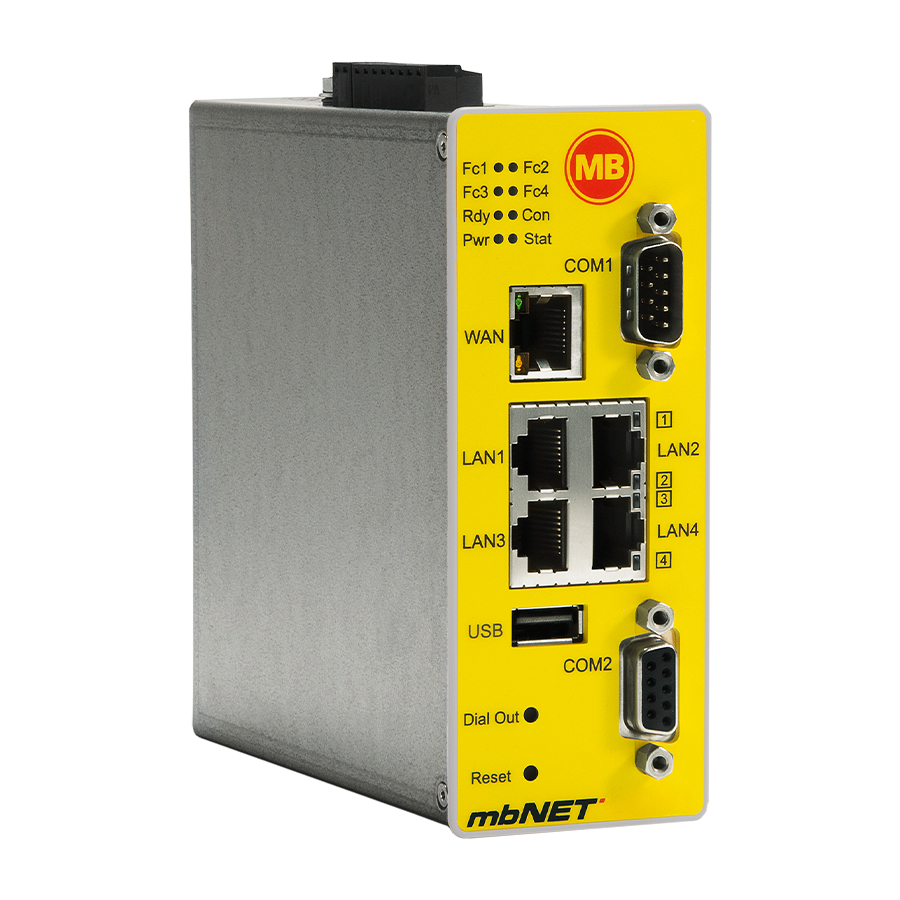
Page 10: Displays, Controls And Connections
Displays, controls and connections galvanically isolated X1 X2 I4 I3 I2 I1 P M O2 O1 Power supply connection 10-30V DC – 0V DC connection Digital input I4 (10-30V) Stat COM1 Digital input I3 (10-30V) Digital input I2 (10-30V) Digital input I1 (10-30V) Fuse-protection 10-30V DC 0V DC connection LAN1 LAN2 Digital output O2 Digital output O1 LAN4 LAN3 1. Function / status LEDs 2. WAN interface COM2 3. - Page 11 Devices with LTE (4G) module SD card SIM 1 SIM 2 Equipment features Type 1 x SD-Kartenschacht MDH 850 MDH 855 2 x SIM-Kartenschacht Div. Main MDH 858 2 x SMA connector SMA connector MDH 859 for GSM antenna (MIMO) Devices with UMTS (3G) module SD card SIM 1 SIM 2 Type Equipment features MDH 814 1 x SD card slot MDH 819 2 x SIM card slot SMA MDH 834 1 x SMA connector connector MDH 849 for GSM antenna Devices with WiFi module SD card...
- Page 12 Function / status LEDs Colour Status Description orange flashes (1 Hz) Data received at COM1 green flashes (1 Hz) Data transmission to COM1 flashes SIMPLY.connect * ready and disabled (5 Hz) This function is only available if the device is set to its factory settings. SIMPLY.connect * ready and activated - activation takes place by pres- sing the Dial Out button. (1 Hz) Data received at COM2 orange flashes green...
- Page 13 Colour Status Description orange Waiting for Bootloader or Signature successfully checked. Check Signature, loads kernel green Waiting for kernel flashes (1 Hz) Loads rootFs Boot process completed - device is ready for use. orange Internet connection established + VPN connection started (1,5 Hz) VPN connection is established flashes green No Internet connection (3 Hz) Internet connection is being made. flashes Internet connection is established. green The power supply to the router is interrupted / the router is not connected to the power supply. Power supply is connected to the terminal block and switched on. Stat flashes (1 Hz) Error in the error memory Found fault The error type can be viewed on the WebGUI of the mbNET under System> Info> „Last error message“. green In connection with the portal mbCONNECT24: User si connected to device (mbNET).
- Page 14 Interfaces and buttons Label Status Description – Router WAN port (customer network, DSL modem ...) LED green Network connection available lights WAN-LED LED flashing Network data transfer active orange LAN 1 - 4 – Local network ports (e.g. machine network) LED green Network connection available lights LAN-LED 1- 4 (Dual LED) LED flashing Network data transfer active orange – Portable USB drive port COM1 port for connecting to devices with RS232 / RS485, RS422 COM1 – interface. COM2 port is for either connecting to devices with MPI interface or ...
-
Page 15: First Time Operation
First time operation Connect, depending on device type, an antenna, and insert a SIM card. Before connecting the router to a network or PC, first ensure that it is properly connected to a power supply, otherwise it may cause damage to other equipment. • Connect equipotential bonding to the grounding lug on the router’s top panel. galvanically isolated I4 I3 I2 I1 P M O2 O1 | X2 | • Connect the (10-30V DC) power supply to the X1 terminal of the router. Make sure that the polarity is correct. ◦ After switching on the supply voltage the Pwr LED lights up and the device performs a system check. ◦ After about 90 sec., both LED Pwr and LED Rdy light up and Fc1 is flashing green (5 Hz - very fast). Stat The mbNET is now ready for operation. - 15 -... - Page 16 First time operation - continued For devices with SIMPLY.connect function The flashing LED Fc1 indicates that the device can be configured for use as a „Cloudserver“ device via the SIMPLY.connect function. SIMPLY.connect is a web application that helps you to set up a device (mbNET) in the Remote Service Portal mbCONNECT24. Stat To activate the function, press the button Dial Out => LED Fc1 lights up. Dial Out Reset => Dial Out If you do not want to use SIMPLY.connect, simply ignore the flashing LED Fc1. More information is available at: https://simplyconnect.mbconnectline.com/ - 16 -...
-
Page 17: Initial Configuration
Initial configuration Requirements: • You have a user account on the Remote Service Portal RSP RSP V 2.x mbCONNECT24 If you do not have a user account on mbCONNECT24, please contact your system administrator or authorized sales partner. For more information about mbCONNECT24 see www.mbconnectline.com in our Download Portal.. • Windows PC with remote client software mbDIALUP * installed . With mbDIALUP you establish a secure VPN connection to mbCONNECT24. * The latest version can be downloaded on www.mbconnectline.com Generally following procedure applies: • Add the mbNET in the portal mbCONNECT24 as a new device. • Enter the necessary basic data, so that the device can connect to the portal (for example, device name, network settings, connection information, etc.). • Transfer the device configuration from the portal into the mbNET. • After the mbNET has been connected to the portal, it can be configured completely there. More information about configuring devices, see the mbNET Manual (download under www.mbconnectline.com) or in the mbCONNECT24 online help. - 17 -... -
Page 18: Initial Configuration Via Rsp Mbconnect24 V
9.1 Initial configuration via RSP mbCONNECT24 V 2.x 9.1.1 Login mbCONNECT24 mbDIALUP ADVICE: Change unconditionally and without delay the default login information! Navigation: Administration > Users 9.1.2 Creating a project Navigation: Administration > Projects In the project overview, click the plus and assign the next screen a Project Name (all other inputs / information can be made up later). - 18 -... -
Page 19: Create A Device
9.1.3 Create a device Navigation: Administration > Projects > Project Alpha (selected project) In the selected project, click the plus and select “Create new device“. For the basic configuration, you only need to select your “Device Type“ and enter a unique device „Name“. You can create your own name for the Device. Following numbers and letters are allowed: 0 to 9, A to Z, a to z (avoid blanks). After saving your settings you will be automatically redirected to the device settings. For the initial configuration here the “Interfaces“ menu is relevant. - 19 -... -
Page 20: Configuring The Device (Connection Data)
9.1.4 Configuring the device (connection data) Navigation: Administration > Projects > Project Alpha (selected project) > NewDecice (selected device) Here the following menus are relevant for the initial configuration: • LAN (all devices) Make sure that the LAN IP and the WAN IP are in different address ranges. • WiFi (devices with WiFi modem) • Internet (all devices) For the initial configuration, it is advisa- ble to select “Always“ in the selection field “Connect to Server at“. -
Page 21: Creating A Configuration
9.1.5 Creating a configuration Navigation: Administration > Projects > Project Alpha (selected project) > NewDecice (selected device) After entering all necessary data, you must transfer the configuration to the mbNET. Therefor connect an USB stick to your configuration PC (the USB stick must have the file format FAT!). Click the Sync icon and select “Download to PC“. The configuration file “mbconnect24.mbn“ can now be downloaded to the USB stick. IMPORTANT: The downloaded configuration file “mbconnect24.mbn“ must not be renamed and must be in the root directory of the USB stick! - 21 -... -
Page 22: Transfer Configuration To The Mbnet
9.1.6 Transfer configuration to the mbNET When the mbNET is ready to operate, insert the USB stick into the USB port of the device. As soon the mbNET recognizes the configuration file, both LED Fc1 + LED Fc2 are flashing. COM1 Now press and hold down the Dial Out button Dial Out until LED Fc3 flashes LAN1 LAN2 Release the Dial Out button LAN4 LAN3 Dial Out The settings from mbCONNECT24 are now automatically copied to the mbNET and the device reboots. COM2 Dial Out If the mbNET is able to connect to the Internet Reset (e.g. network, telephone cable, SIM card, antenna ... -
Page 23: Access The Web Interface Of The Mbnet
10 Access the web interface of the mbNET On the web interface of the mbNET a Status page and a Diagnostic page is available. On the Status page, five steps with additional information are displayed, which must be run through when connecting the mbNET with the portal. The Diagnostic page helps you in case of a failed connection establishment in trobleshooting. Requirements: • The configuration PC and the mbNET must be in the same IP address range. Depending on the LAN IP that you assigned to the device in the portal, you may need to assign the configuration PC to the same address range. If you assigned the mbNET e.g. the LAN IP 192.168.2.200, you need the configuration PC to assign the same address range (192.168.2.X). This applies to both the IP address and subnet mask. • The mbNET must be accessible via the LAN interface of the configuration PC. Start a browser and enter the LAN IP you have assigned in the portal to the mbNET. To log on to mbNET enter the following data: Username: admin Password: The default password is located on the back of the device. - 23 -... -
Page 24: Quick Start
10.1 Quick Start After a successful login you will see in the Quick Start menu the device state. Here, five steps are displayed that are required so that the device can connect to the portal. = everything OK = processing = Error Click on the icon to the right of each progress to get details / information about this step. If all five steps have been completed successfully, the mbNET is connected to the portal mbCONNECT24. - 24 -... -
Page 25: Diagnostics
10.2 Diagnostics In case of a failed connection setup, the Diagnostic page supports for trobleshooting. The respective result of the individual, independent functions / commands you need, inter alia in case of support. 11 Factory settings on delivery The mbNET is delivered with the following factory settings: ADVICE: IP address 192.168.0.100 Change unconditionally and without delay the default login information! Subnet mask 255.255.255.0 Username admin Password The default password is located on the back of the device. NOTICE Keep the device default password in a safe place. You need the default password during the initial configuration and after each loading the factory settings. - 25 -... -
Page 26: Loading The Factory Settings
12 Loading the factory settings NOTICE Before you configure the device to its factory settings, you should note the following: • Save your configuration first. After restoring the factory settings, all of your settings/ changes will be deleted. • The IP address of the device is reset to the original IP address (192.168.0.100). • You may also need to modify the network settings of the configuration PC accordingly. • The device password is reset to its individual default password. The default password can be found on the back of the unit. • No USB stick/storage medium should be connected to the device. Execution: 1. Switch on the mbNET or press the Reset button. 2. Wait until the LED Rdy flashes green. 3. Press and hold the Dial Out button until LED Fc4 is lit. 4. Press the Dial Out button again => LED Fc3 lights up. 5. Repeat step 4. => LED FC2 lights up. 6. Press the Dial Out => button one last time, after approximately 10 - 20 sec. LED Fc3 flashes. -
Page 27: Technical Data
13 Technical Data Performance data Voltage V (DC) 10 – 30 V DC (external Power Supply or other SELV Power Supply Source, rated 10-30V DC, max. 40A) Power consumption max. 1300 mA @ 24 V IP protection class IP 30 * Area of application Dry environments Operating temperature -40 – +75 °C Storage temperature -40 – +85 °C Humidity 0 – 95% (non condensing) Real-time clock In case of power failure the date and time remain up to 7 days (depending on the ambient temperature). Dimensions (max.) 48 mm x 137 mm x 140 mm (W x D x H) Weight (max.) 650 g Housing / material metal Mounting DIN rail mounting (based on DIN EN 50022) * At full occupancy of all connections and interfaces. Alternatively, unused interfaces can be covered with dust protection plugs. I/Os and standard interfaces Digital inputs 4 pcs. digital inputs, 10 – 30 V DC (galvanically isolated), ... -
Page 28: Technical Support
14 Technical Support For technical support (FAQ, troubleshooting, most recent information, etc.) see our website www.mbconnectline.com. For support enquiries, always give the serial number of your router. E-mail: support@mbconnectline.com Tel.: (EU) +49 (0) 98 51 / 58 25 29 900 / (US) +1-630-797-6067 SIMPLIFIED EU DECLARATION OF CONFORMITY Hereby, MB connect line GmbH declares that the radio equipment types MDH811; -814; -819; -831; -834; -841; -849; -850 EU; -855 EU; -858 EU; -859 EU are in compliance with Directive 2014/53/EU. The full text of the EU declaration of conformity is available at the following internet address: www.mbconnectline.com NOTICE Device types MDH 850 AT&T, MDH 855 AT&T, MDH 858 AT&T, MDH 859 AT&T bear no CE marking and may not be used or put into operation in the European economic area (EEA)! MB connect line GmbH Fernwartungssysteme Winnettener Str. 6 91550 Dinkelsbühl Germany PROG. CNTLR. + 49 (0) 700 / MBCONNECT E482663 + 49 (0) 700 / 62 26 66 32 www.mbconnectline.com © MB CONNECT LINE 1997 – 2019 - 28 -...
Need help?
Do you have a question about the mbNET MDH859 and is the answer not in the manual?
Questions and answers