Table of Contents
Advertisement
Advertisement
Table of Contents

Subscribe to Our Youtube Channel
Related Manuals for MB Connect Line mbNET.mini


Summary of Contents for MB Connect Line mbNET.mini
- Page 1 User Manual Version: 1.6.0 DR 03 (10.01.2017) - EN...
- Page 2 We welcome comments, suggestions for improvement or constructive criticism at any time. Hereby MB CONNECT LINE acknowledges that the device mbNET.mini (MDH86xx) is in complies with the essential requirements and other relevant provisions of directive 1999/5/EC. The declaration of conformity can be found at: www.mbconnectline.com...
-
Page 3: Table Of Contents
10.1.3.4.5 Modem Settings......................30 10.1.4 Transferring the configuration to the Device..............31 10.1.4.1 Download to PC......................32 10.1.4.1.1 Importing the configuration into the mbNET.mini............. 32 10.1.4.2 Prepare for Synchronization..................33 10.1.4.3 Transferring configuration to the device - via mbDIALUP........... 34 10.1.5 Access to devices and machines................... 35 10.1.6 Quit the... - Page 4 10.2.2.1 Download configuration to PC - via USB..............44 10.2.2.2 Transfer configuration to the device - via CTM............45 10.2.2.3 Transferring configuration to the device - via mbDIALUP........... 46 10.3 Initial configuration via the web interface of the mbNET.mini............ 47 10.3.1 Firststart.......................... 47 10.3.2 Device State........................52 10.3.2.1 Five Step Status Check....................53...
- Page 5 14.1 Firmware update via USB......................84 14.2 Firmware update via RSP mbCONNECT24................85 Technical Data.............................86 15.1 Technical data MDH 860......................86 15.2 Technical data MDH 861......................87 15.3 Technical data MDH 862 AT&T....................88 15.4 Technical data MDH 862 EU......................89 15.5 Technical data MDH 863......................90 | Page 5 of 90...
-
Page 6: General
This user manual describes the functions and use of the mbNET.mini router MDH86x. Please read carefully and retain this information. Validity of this documentation This manual is valid for the router mbNET.mini MDH 860, MDH 861, MDH 862, MDH 863, from firmware version V 1.5. Prerequisites / additional required components The following end devices are suitable for connecting to the mymbCONNECT24.virtual server:... - Page 7 Currently manuals and more information The latest manuals and more information about products related to secure remote maintenance can be found on www.mbconnectline.com in the download portal. General | Page 7 of 90...
-
Page 8: Safety Instructions
Proper use The mbNET.mini router may be used only as described in the manual. Disclaimer In this manual all technical information, data and instructions for installation, operation and maintenance are based on our previous experience and insights to the best knowledge. -
Page 9: Notes On Cyber-Security
Notes on Cyber-Security Note the following safety recommendations in order not to prevent unauthorized access to the system. General • Make sure at regular intervals that all relevant components these recommendations and, if necessary, meet other internal security guidelines. • Evaluate your system holistically in terms of safety. Take a cell protection concept with corresponding products. -
Page 10: Functional Overview
The industrial router mbNET.mini offers you optimum flexibility and security, making remote communication with your systems both easy and secure. Thanks to its compact design, the mbNET.mini router will fit into any switch cabinet and provides the perfect system for connecting to different components. The router can be... -
Page 11: Included In Delivery
MDH 862 MDH 863 Quick Start Guide GSM antenna Quick Start Guide Should any of these parts are missing or damaged, please contact the following address: MB CONNECT LINE GMBH Winnettener Str. 6 D-91550 Dinkelsbühl Tel.: +49 (0)9851/282529-0 Fax: +49 (0)9851/282529-99 Please keep the original box and the original packaging in case you need to send the device for repair at a later date. -
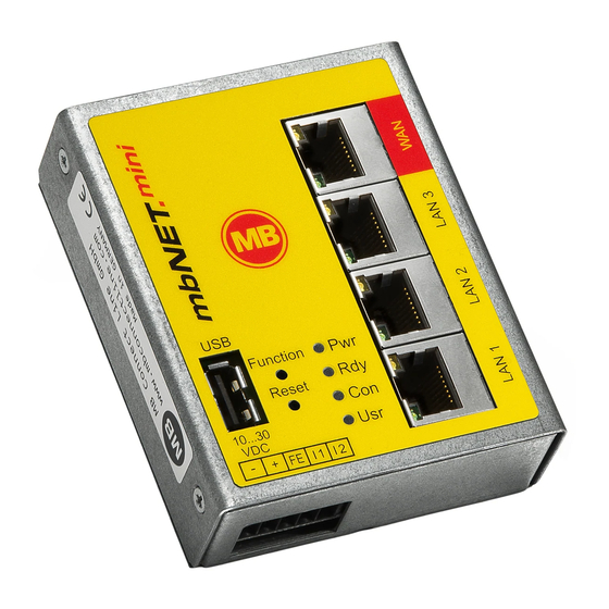
Page 12: Displays, Controls And Connections
Displays, controls and connections View of front of the device MDH 860 MDH 861 MDH 862 MDH 863 1 x WAN; 3 x LAN; USB GSM 3G; 4 x LAN; USB GSM 4G; 4 x LAN; USB WAN; 4 x LAN; USB Designation Status Description... - Page 13 Designation Status Description Transfer of configuration from USB stick to mbNET.mini. Transfer of firmware from USB stick to mbNET.mini. Access to free application data via SFTP. Function This button has three functions and is used according to the status. 1 Establishing connection to portal (depending on configuration)
-
Page 14: Interface Assignment
Interface assignment Pinout of the terminal block on the bottom of the device 0V DC connection Power source connection 10-30V DC FE Functional earth Digital input I1 (10-30V DC) Digital input I2 (10-30V DC) * Input 1 can only be configured for establishing the connection to the portal mbCONNECT24. ** Input 2 can be cofigured to send emails, SMS, Internet SMS or to start a reboot. -
Page 15: Getting Started
(approx. 90 sec). The mbNET.mini is now ready for operation. T + 25 sec T + 90 sec For further support on the mbNET.mini, visit our website on www.mbconnectline.com. Getting started | Page 15 of 90... -
Page 16: Initial Configuration
Initial configuration Because the mbNET.mini was designed as a portal device, the initial start-up takes place via the web portal • RSP mbCONNECT24 V 2.x oder • mbCONNECT24 V1.x Generally following procedure applies: • Add the mbNET.mini in the portal as a new device. -
Page 17: Initial Configuration Via Rsp Mbconnect24 V 2.0
NENCT24 and how you connect to the portal. Here you can see how to create a device and perform the initial config- uration for your mbNET.mini. In this section you will learn the dif- ferent methods, how to transfer the initial configuration to the mb- NET.mini. -
Page 18: Account Request - Software Download
10.1.1 Account request - Software download If you do not have an account for mbCONNECT24 • Go to www.mbconnect24.net or www.mb- connectline.com. • Click the button "mbCONNECT24 account request" The button you find above the navigation menue at the top of the screen. Nach erfolgter Anmeldung erhalten Sie a) eine Bestätigungs-Mail mit Ihrem Benutzernamen b) eine zweite E-Mail mit Ihrem Passwort... -
Page 19: Connect To Rsp Mbconnect24
10.1.2 Connect to RSP mbCONNECT24 Selecting the server Start mbDIALUP and select from the pull-down menu "Server" your mbCONNECT24 server. • rsp.mbconnect24.net (EU) for server location EUROPE • rsp.mbconnect24.us (US/CAN) for server location USA/Canada ADVI C E The server location can be seen in the confirmation email for subscibing to mbCONNECT24. Access via the proxy server If the Internet can only be accessed via a proxy serv- er, the relevant settings can be applied in the menu... -
Page 20: Mbconnect24 Configuration
10.1.3 mbCONNECT24 Configuration Here you do • change your password • create a new project • create a new device • generate a configuration file and • transfer it to your mbNET or mbSPIDER 10.1.3.1 Changing your password After your first Login at the portal, you are required to change your password. - Page 21 Click the "Administration" button under the Note: "There are no projects defined in your account. Go to the Administration Section to create your first project!" On the next window, click "+ Create new Project". For the basic configuration, it is necessary to fill in the following information: •...
-
Page 22: Create A New Device
10.1.3.3 Create a new device After you have defined a Project, it appears follow- ing announcement: : "There are no Devices defined in this Project. Click on the button to create your first Device in this Project!" Click on the button „+ Create new Device“. For the basic configuration, you only need the follow- ing data in the tab “Device”. -
Page 23: Create A Configuration
10.1.3.4 Create a configuration After you have created a Device, the ac- tual configuration menu appears. For the basic configuration are solely the following Interfaces necessary. • LAN • WiFi • Internet • WAN • Modem ADVI C E According to the Type of your Device, the list of the interfaces could variegate. Click the edit icon to make the settings on the submenus. -
Page 24: Lan Settings
10.1.3.4.1 LAN Settings Enter a free LAN IP address and the Netmask from your system or machine network. AD VI CE Notice, that the LAN and WAN IP-address should use a different address range. LAN Settings Enter the IP-address of your Device Netmask Enter the Subnetmask where your Device should be integrated. -
Page 25: Wifi Settings
10.1.3.4.2 WiFi Settings WiFi Access If you want to configure a Device with a WLAN- module, enter the information of your Router or Ac- cess-point. WiFi Access SSID Mandatory field: Enter the name of the WiFi network to which the device should connect. - Page 26 WAN Settings - WANType: Static IP WAN Settings - WAN Type: Static IP WAN Type Selection field for the WAN type (DHCP or Static IP) WAN IP Mandatory field: Enter the IP-Address of the external Router WAN Netmask Mandatory field: Enter the Subnet mask where your Device should be integrated. Gateway Mandatory field: Enter the Gateway of the external Router.
-
Page 27: Internet Settings
10.1.3.4.3 Internet Settings You will need to specify: • when the device should be connected to the portal • how the Internet connection should be estab- lished • which VPN port should be used (which of the three ports is free was determined by mbCHECK) AD VI CE For the First Configuration it is advisable to select... - Page 28 Internetconnection Selection field with the available options (depending on device and device type) how you want to connect to the Internet. To connect the device through an external router to the In- ternet, you need to assign the device an IP address from the External Router range of the external router.
-
Page 29: Wan Settings
10.1.3.4.4 WAN Settings Enter a free WAN IP address and the net mask from your system or machine network. It is not compelling to make an entry, just if you have plugged in the WAN-connector. If you have a Device with a modem module, you do not need the WAN IP-address. -
Page 30: Modem Settings
10.1.3.4.5 Modem Settings Modem Settings Telephone number Enter the mobile number of your device. Mobile APN (Provider) Select the APN of your Provider, if it is in the list. Enter the APN of your provider manually. User If necessary, enter your Username. Password If necessary, enter your Password. -
Page 31: Transferring The Configuration To The Device
10.1.4 Transferring the configuration to the Device The following options are available for transfer of the configuration file (mbconnect24.mbn / -.mbnx): • Download to PC • Prepare for Synchronization • Submit to Device Download to PC Here you download the configuration to your PC or directly to a USB stick. -
Page 32: Download To Pc
USB drive. The USB drive must have the file format FAT! 10.1.4.1.1 Importing the configuration into the mbNET.mini When the mbNET.mini is connected to the power supply and is ready for operation, insert the USB stick with the configuration file on it into the USB port of the device. -
Page 33: Prepare For Synchronization
"Prepare for Synchronization". No further settings are necessary for the basic configuration. Click on "Synchronize". Once the mbNET.mini has logged into the portal, the configuration is transferred to the device. Your mbNET.mini is now online. Initial configuration | Page 33 of 90... -
Page 34: Transferring Configuration To The Device - Via Mbdialup
"Finished" button. If the mbNET.mini is able to connect to the Internet (e.g. network, telephone cable, SIM card, antennae in- stalled), the device will subsequently log in to your account. This is displayed by the flashing LED Con. -
Page 35: Access To Devices And Machines
10.1.5 Access to devices and machines If the mbNET.mini has an internet connection and the device is signed in, the LED shines green in the status bar. If you want a connection to a machine you have to click the „Connection“-Icon After the connection is established, the LED changes the color from green to orange. -
Page 36: Initial Configuration Via Mbconnect24 V 1.X
NECT24 portal server. Alternatively, you can connect via a web browser over a secure https VPN connection to the Portal Server. • Type and serial number of your mbNET.mini ADVI C E For more information about mbCONNECT24 V 1.x see mbconnectline.com. -
Page 37: Adding A New Device (Mbconnect24 V 1.X)
ADVI C E Change unconditionally and without delay your password after your first login. To do this, click your user in the top menu bar. Change your password in the "Profile" win- dow that appears next. Once you have saved the changes, your new password is effective the next time you log in to the portal. -
Page 38: Description - All Devises
10.2.1.1 Description - all devises Description Once you have added the new device, the actual configuration menu opens. Depending on the device type selected, the input/drop-down fields may vary here. Location Enter your device's location here. Contact Enter your contact details here (e.g. a contact person in the device's location). -
Page 39: Network (Mdh 860, 861, 862, 863)
10.2.1.2 Network (MDH 860, 861, 862, 863) Network MDH 860, MDH 861, MDH 862, MDH 863 Enter a free LAN IP address and the subnet mask from your system or machine network here. Activate the "1:1NAT Network" when both tunnel end points have the same network address to enable communi- cation through both networks. -
Page 40: Internet
10.2.1.3 Internet 10.2.1.3.1 WAN device (MDH 860) Select: When the device should be connected to the portal. Which interface type (DHCP or static IP) should be used. WAN settings for DHCP Select this setting if there is a DHCP server on the net- work, which is therefore automatically assigned a new IP address by the industrial router. -
Page 41: Wan Device (Mdh 861, 862)
10.2.1.3.2 WAN device (MDH 861, 862) Basic settings: Determine when the device should connect to the portal. Select the mobile APN of your provider (if your provider does not appear in the list, you can also enter the APN (access point name) manually un- der "Own entry - enter login information"). -
Page 42: Wifi Device (Mdh 863)
10.2.1.3.3 WiFi device (MDH 863) Select: When the device should be connected to the portal. Which interface type (DHCP or static IP) should be used. WiFi WAN settings for DHCP Select this setting if there is a DHCP server on the net- work, which is therefore automatically assigned a new IP address by the industrial router. -
Page 43: Transferring The Configuration To Mbnet.mini
10.2.2 Transferring the configuration to mbNET.mini The following options are available for transferring the configuration file: • Download to PC • Prepare for CTM • Submit to Device Once you have created a new device, click on the disk symbol to select the transfer type... -
Page 44: Download Configuration To Pc - Via Usb
10.2.2.1 Download configuration to PC - via USB Select this transfer type if the mbNET.mini is neither connected to a computer via LAN nor has a connection to the mbCONNECT24 portal. The "mbconnect24.mbn/-.mbnx" configuration file is saved on the configuration PC or directly on a USB drive con-nected to it. -
Page 45: Transfer Configuration To The Device - Via Ctm
CTM (Configuration Transfer Manager) to be collected by the mbNET.mini. On the interface of the mbNET.mini, create an initial configuration so the device can connect to the portal. The mbNET.mini will then collect its portal configuration from the CTM there. -
Page 46: Transferring Configuration To The Device - Via Mbdialup
10.2.2.3 Transferring configuration to the device - via mbDIALUP For this, the mbNET.mini must be accessible from a PC on the LAN, irrespective of its LAN IP, and the computer must have a connection to mbCONNECT24 portal. After clicking "Submit configuration to de- vice", the system performs a scan of all de-... -
Page 47: Initial Configuration Via The Web Interface Of The Mbnet.mini
10.3 Initial configuration via the web interface of the mbNET.mini Connect one the mbNET.mini to the power supply. Connect the mbNET.mini via one of the LAN interfaces to the Ethernet interface on your configuration PC. ADVI C E The configuration PC and the mbNET.mini must be in the IP address range (192.168.0.X). - Page 48 In the selection box "Internetconnection", see the de- fault value the respective device. This value can not be changed. • External router when using WAN and WLAN devices (MDH 860, MDH 863) • Modem when using modem devices (MDH 861, MDH 862) To continue click on „Next>>“...
- Page 49 Proxy Enter the information for your proxy. To continue click on „Next>>“ Modem (MDH 861, MDH 862) Enter the APN provider and the SIM PIN here. That is possible in "Network (Provider)" a list of providers. If your provider can not be found in the list, you can fill in each field individually.
- Page 50 WLAN Settings - Connection with the Access Point (MDH 863) Enter the necessary data in order to connect to the Access Point. SSID Mandatory field: Enter the name of the WiFi network to which the device should connect. Authetification Selection field for the authentication Mode mode.
- Page 51 Finish (MDH 860, MDH 861, MDH 862, MDH 863) Clicking the "Apply" button saves your settings. The mbNET.mini now tries to establish a connection to the portal in order to download his portal configura- tion. For this purpose, the display of the web interface switches to the status display.
-
Page 52: Device State
10.3.2 Device State The status page of the device opens automatically a) after completing the "First Start" menu by click- ing the "Apply" button b) at each future access to the web interface of the device Here all steps are shown, which are necessary so that the device can establish a connection to portal. -
Page 53: Five Step Status Check
10.3.2.1 Five Step Status Check MDH 860 Device Here the device network settings and basic data is request- MDH 861, MDH 862 Input 1 can only be configured for establishing the connec- tion. Is it configured accordingly, it is displayed here. The state of the signal is shown with the prepended soft- LED (grey = 0/low, green = 1/high). - Page 54 Availability of the Portal Server Here the current accessibility of the Portal Server is re- all device types quested and displayed the results. DNS: Portal Server address NTP: NTP time server (the NTP is checked only if it is en- abled in the configuration).
- Page 55 Information on the CTM, cloud server and user Here, the following information is displayed: all device types Connection status to the Portal Server and Portal Address Portal Server Account name Device name Information whether a portal configuration is available for CTM / Synchronization status download.
-
Page 56: Diagnostics
10.3.3 Diagnostics In case of a failed connection setup, the diagnostic page supports for troubleshooting. The respective re- sult of the individual, independent functions / com- mands you need, inter alia in case of support. Ping Here, it is possible to enter an internet page or an IP address. When actuating the "Ping"... -
Page 57: Configuring Your Router In The Portal (V 1.X)
ADVI C E All settings and changes are only effective after they have been transferred as a configuration on the device (see chapter Transferring the configuration to mbNET.mini). Configuring Your Router in the Portal (V 1.x) | Page 57 of 90... -
Page 58: System Settings
11.1 System > Settings 11.1.1 System Settings Here you choose if and when the mbNET.mini should reboot. Input => natural numbers [h]. If you leave this blank or enter 0, it will not reboot. 11.1.2 Time Settings Enter the current date and time here, even if you are activating an NTP server. -
Page 59: Mail Settings
11.1.3 Mail Settings Selecting "Yes" in "Activate automatic Mail" means that the router will use MB connect line's mail server and fixed parameters. Selecting "No" in "Activate automatic Mail" means that you must en- ter the necessary details of your mail server. -
Page 60: System > Usb
11.3 System > USB USB Access from Network When "Active" is checked, the USB memory can be accessed via an SFTP client. Default settings: „SFTP Username“: ftp „SFTP Password“: ftp Page 60 of 90 | Version: 1.6.0 DR 03 (10.01.2017) - EN | 10.01.2017... -
Page 61: System > Logging
"Debug in- formation". "Log also to USB-Device" additional logging outputs can only be accessed on the USB stick, which is connected to the mbNET.mini (file name of the logging file: "Device name.log"). Remote Logging: "Enable Remote logging"... -
Page 62: Security > Firewall General
11.5 Security > Firewall General The mbNET.mini has an integrated firewall to protect against third-party and unauthorized access and con- nection attempts. Incoming and outgoing data traffic is checked, logged and allowed or denied via this firewall. The firewall can generally be configured with one of the following three settings: •... -
Page 63: Security > Wan>Lan
11.6 Security > WAN>LAN This setting governs the incoming data traffic, i.e. the following settings only apply to data traffic arriving from outside the network. Sample setting The following rule applies according to the device type: If the connection is established to the Internet via WAN (external router, fixed line), the WAN Ethernet port is the gateway to the Internet. -
Page 64: Security > Lan>Wan
11.7 Security > LAN>WAN The LAN_WAN Configuration governs the outgoing data traffic, i.e. the following settings only apply to outgoing data traffic. Designation Description Enable If the box has been checked, the following settings will be active after saving. Action The following options are available for selection: Drop: If this option is selected, it means that no data packets can pass and the packets are delet- ed immediately. -
Page 65: Security > Forwarding
11.8 Security > Forwarding Designation Description Enable If the box has been checked, the following settings will be active after saving. Source IP You can enter the IP from which data packets are to be received here. If an entry is made here, only packets from this one address are forwarded. Source Port You can specify the port via which the data packets arrive here. -
Page 66: Security > Nat
11.9 Security > NAT The NAT Configuration enables two networks in the same address range to be connected. If, for example, a network with the address 192.168.0.0/24 is to be connected to a network with the same address, this is only possible if one of the two networks is assigned another address. -
Page 67: Alarmmanagement > Input
Only digital input 2 can be used to send emails, text messages, Internet text messages or to restart the device. After the device has accepted the configuration, the config- uration is shown on the start page of the mbNET.mini in the information under Step 1. The state of Input 2's signal is shown with the prepended soft-LED (grey = 0/low, green = 1/high). -
Page 68: Passwords (Password Settings)
Change the device password to prevent unauthorized access to the device. ADVI C E These and all changes that you make for the mbNET.mini in the portal will only take effect when the set- tings/changes made are transferred to the device as a configuration. -
Page 69: Configuring Your Router In The Remote Service Portal (V 2.X)
(Firewall Security Levels) and create Firewall rules. Alarmmanagement - here you can configure the digital in- put 2 of the mbNET.mini. VPN - here, you can choose a VPN port and, if necessary, a VPN gateway. User Administration - here you change the password for accessing the device GUI. -
Page 70: System Settings
12.1 System Settings Navigation: Administration > Projects > Project Gama (selected project) > GamaRouter (selected device) > Services > System Settings The overview shows • After which time the device is to perform a re- boot automatically • The currently installed firmware version, with a note of its actuality ADVI C E The orange LED... -
Page 71: Mail Settings
12.2 Mail Settings Navigation: Administration > Projects > Project Gama (selected project) > GamaRouter (selected device) > Services > Mail Settings In the Mail Settings, you can choose whether the device should use the mail server of the portal with fixed specifications or whether you use your own SMTP server. -
Page 72: Firewall
12.3 Firewall Navigation: Administration > Projects > Project Gama (selected project) > GamaRouter (selected device) > Services > Firewall Here you • define the global firewall settings (firewall secu- rity levels) - therefor click on the edit icon • create firewall rules and manage them - therefor click on "Firewall"... -
Page 73: Firewall Rules
12.3.2 Firewall Rules Create and manage the firewall entry / exit rules here • WAN > LAN • LAN > WAN • FORWARDING • NAT To add a rule, proceed as follows: • Click on the plus sign in the header row •... -
Page 74: Alarmmanagement
12.4 Alarmmanagement Navigation: Administration > Projects > Project Gama (selected project) > GamaRouter (selected device) > Services > Alarmmanagement Here you can configure the Input 2 of the device for performing the following actions. - send E-Mail - System Reboot - send SMS - send Internet-SMS Click on "Alarmmanagement"... -
Page 75: Vpn
12.5 VPN Navigation: Administration > Projects > Project Gama (selected project) > GamaRouter (selected device) > Services > VPN In the VPN settings you can choose a VPN port and, if necessary, a VPN gateway. To change the settings, click on the Edit button VPN Port Here you can select a vacant VPN port but make sure that this port is enabled in the fire- wall. -
Page 76: User Administration
12.6 User Administration Navigation: Administration > Projects > Project Gama (selected project) > GamaRouter (selected device) > Services> User Administration Here you change the password for accessing the de- vice GUI. To change the settings, click on the Edit button Admin Passwort Enter your new password. -
Page 77: Ntp Server
12.7 NTP Server Navigation: Administration > Projects > Project Gama (selected project) > GamaRouter (selected device) > Services > NTP Server The Network Time Protocol (NTP) is a standard for synchronizing clocks in computer systems via pack- age-based communication networks. The automatic time calibration takes place via an NTP server (preset address: 0.de.pool.ntp.org). -
Page 78: Time Zone
12.8 Time Zone Navigation: Administration > Projects > Project Gama (selected project) > GamaRouter (selected device) > Services > Time Zone Here you enter the standard time and the de- fault date and select the time zone. To change the settings, click on the Edit button Standard date/time Input of the date/time in the UTC [YYYY.MM.DD-HH:M-... -
Page 79: Web Server
12.9 Web Server Navigation: Administration > Projects > Project Gama (selected project) > GamaRouter (selected project) > Services > Web Server In the Web Server settings you select the connec- tion type (HTTP or HTTPS) how you want to access the Web server, and if necessary, change the default port. -
Page 80: Direct Device Web2Go
12.10Direct Device Web2go Navigation: Administration > Projects > Project Gama (selected project) > GamaRouter (selected device) > Services > Direct Device Web2go Using this function, you can access the web interface of the device directly, via the green button. To change the settings, click on the Edit button Designation Description Checkbox for activating/deactivating direct ac-... -
Page 81: Logging
12.11Logging Navigation: Administration > Projects > Project Gama (selected project) > GamaRouter (selected device) > Services > Logging Here you define the logging options. To change the settings, click on the Edit button Designation Description Output Debug Information Checkbox for activating/deactivating Debug mode for various logging functions. This func- to Logging Server tion allows extended logging. -
Page 82: Loading The Factory Settings
Function When the LED Pwr and Rdy light up, the factory settings have been loaded The mbNET.mini is now ready for operation and be configured again. Page 82 of 90 | Version: 1.6.0 DR 03 (10.01.2017) - EN | 10.01.2017... -
Page 83: Firmware Update
Generally you can perform a firmware update via the USB interface of the device. The latest firmware version can be found in the download area on www.mbconnectline.com. If you operate your mbNET.mini in association with the RSP mbCONNECT24 version 2.x, you can perform the firmware update via the portal. -
Page 84: Firmware Update Via Usb
USB drive. The USB drive must have the file format FAT! • When the mbNET.mini is ready for operation (LED Pwr + RDY light up), plug the USB stick into the USB port of the device. The device detects the configuration file and shows this by rapidly blinking LED Usr (flashing frequency: 3 Hz). -
Page 85: Firmware Update Via Rsp Mbconnect24
14.2 Firmware update via RSP mbCONNECT24 Navigation: Administration > Projects > Project Gama (selected project) > GamaRouter (selected device) > Services Prerequisites: • You operate the device in the RSP mbCONNECT24 V 2.x. • The device is online in the portal. How to do: Call up the device settings of the rele- vant device. -
Page 86: Technical Data
Technical Data 15.1 Technical data MDH 860 MDH 860 - mbNet.mini with WAN • 1x WAN • 3x LAN (3-port switch) • 1x USB host • 2x digital input • Connection only possible to the portal (mbCONNECT24, mymbCONNECT24.hosted, -.mini, -.midi, -.maxi, -.virtual) -
Page 87: Technical Data Mdh 861
15.2 Technical data MDH 861 MDH 861 - mbNet.mini with 3G modem • 4x LAN (4-port switch) • 1x USB host • 2x digital input • 1x SIM-Cart slot • 1x 3G modem • Supported networks: GPRS | EDGE | UMTS | HSPA+ •... -
Page 88: Technical Data Mdh 862 At&T
15.3 Technical data MDH 862 AT&T MDH 862 AT&T - mbNet.mini with 4G modem • 4x LAN (4-port switch) • 1x USB host • 2x digital input • 1x SIM-Cart slot • 1x 4G modem • Supported networks: 2G, 3G, LTE •... -
Page 89: Technical Data Mdh 862 Eu
15.4 Technical data MDH 862 EU MDH 862 EU - mbNet.mini with 4G modem • 4x LAN (4-port switch) • 1x USB host • 2x digital input • 1x SIM-Cart slot • 1x 4G modem • Supported networks: 2G, 3G, LTE •... -
Page 90: Technical Data Mdh 863
15.5 Technical data MDH 863 MDH 863 - mbNet.mini with WiFi • 4x LAN (4-port switch) • 1x USB host • 2x digital input • 1x WiFi module • Connection only possible to the portal (mbCONNECT24, mymbCONNECT24.hosted, -.mini, -.midi, -.maxi, -.virtual)
Need help?
Do you have a question about the mbNET.mini and is the answer not in the manual?
Questions and answers