Table of Contents
Advertisement
Advertisement
Table of Contents

Subscribe to Our Youtube Channel
Related Manuals for MB Connect Line mbNET Series


Summary of Contents for MB Connect Line mbNET Series
- Page 1 MDH800 – MDH859 MDH800 – MDH859 Quick start-up guide V 3�3�5 14�12�2017...
-
Page 2: Table Of Contents
Table of contents Safety instructions ��������������������������������������������������������������������������������������������������������������� 3 Using Open Source Software ���������������������������������������������������������������������������������������������� 4 2�1 General Information ������������������������������������������������������������������������������������������������������� 4 2�2 Special Liability Regulations ������������������������������������������������������������������������������������������ 5 Included in delivery ������������������������������������������������������������������������������������������������������������� 6 Performance characteristics ����������������������������������������������������������������������������������������������� 8 Displays, controls and connections ����������������������������������������������������������������������������������� 9 First time operation ������������������������������������������������������������������������������������������������������������ 12 Initial configuration ������������������������������������������������������������������������������������������������������������... -
Page 3: Safety Instructions
This Quick Start Guide provides a quick Overview of selected operating procedures and functions of the mbNET industrial router (MDH800 – MDH859). However, the detailed manual with the important Notes and safety instructions can NOT be replaced by this document. Read the following instructions carefully and keep them in a safe. Latest information, up- dates and the complete Manual, visit our website at www.mbconnectline.com. 1 Safety instructions Opening up the device voids the • Only qualified specialist personnel may install, start up, and operate the router. The warranty! national safety and accident prevention regulations must be observed. NOTE: elctrostatic discharge! Observe the necessary safety • The router is built to the latest technological precautions when handling com- standards and recognized safety standards ponents that are vulnerable (see Declaration of Conformity). to electrostatic discharge (EN 61340-5-1 • The router is only intended for operation in and IEC 61340-5-1)! the control cabinet and with SELV according The mbNET routers are maintenance-free to IEC 60950/EN 60950/VDE 0805. units� • The router may only be connected to If a mbNET router have damage or mal- devices, which meet the requirements of function, the device must be immediately... -
Page 4: Using Open Source Software
2 Using Open Source Software 2.1 General Information Our products contain, amongst others, so-called open-source software that is provided by third parties and has been published for free public use. The open-source software is subject to special open-source software licenses and the copyright of third parties. Basically, each customer can use the open-source soft-ware freely in compliance with the licensing terms of the respective producers. The rights of the customer to use the open-source software beyond the purpose of our products are regulated in detail by the respective concerned open-source software licenses. The customer use the open-source software freely, as provided in the respective effective license, beyond the pur- pose that the open-source software gets in our products. In case there is a contradiction between the licensing terms for one of our products and the respective open-source software license, the respective relevant open-source software license takes priority over our licensing terms, as far as the respective open-source software is concerned by this. The use of the used open-source software is possible free of charge. We do not demand usage fees or any comparable fees for the use of the open-source software contained in our products. The use of the open-source software in our products by the customer is not part of the earnings we achieve with the contractual compensation. All open-source software programs contained in our products can be taken from the available list. The most important open-source software licenses are listed in the Licenses section at the end of this publication. As far as programs contained in our products are subject to the GNU General Public License (GPL), GNU Lesser General Public License (LGPL), the Berkeley Software Distribution (BSD), the Massachusetts Institute of Technology (MIT) or another open-source software license, which regulates that the source code must be made available, and if this software is not already delivered... -
Page 5: 2�2 Special Liability Regulations
Requests must be directed to the following address, if possible under specification of the serial number: MB CONNECT LINE GMBH Tel. +49 (0) 98 51 / 58 25 29 0 Fernwartungssysteme Fax +49 (0) 98 51 / 58 25 29 99 Winnettener Str. 6 info@mbconnectline.com 91550 Dinkelsbühl GERMANY 2.2 Special Liability Regulations We do not assume any warranty or liability, if the open-source software programs contained in our product are used by the customer in a manner that does not com-ply any more with the purpose of the contract, which is the basis of the acquisition of our product. This concerns in particular any use of the open-source software programs outside of our product. The warranty and liability regula- tions that are pro-vided by the respective effective open-source software license for the respective open-source software as listed in the following are effective for the use of the open-source software beyond the purpose of the contract. In particular, we are not liable, if the open-source software in our product or the complete software configu-ration in our product is changed. The warranty granted with the contract, which is the basis of the acquisition of our product, is only effective for the unchanged open-source software and the unchanged software configuration in our product. -
Page 6: Included In Delivery
3 Included in delivery Please check that your delivery is complete: All device types 1 x Industrial router mbNET 1 x Ethernet cabel, 1:1, 2 m 1 x Quick start-up guide (Fig. Representative) Art.-No.: 8.002.201.00.00 Art.-No.: 1.920.000.01.00 Device types with analog modem Device types with ISDN modem MDH 800; MDH 810; MDH 815; MDH 830 MDH 802; MDH 812; MDH 817; MDH 832 1 x Telephone cable 1 x TAE adapter 1 x Telephone cable RJ11-RJ45... - Page 7 MDH 818; MDH 819; MDH 833; MDH 834; MDH 848; MDH 849; MDH 850; MDH 855; MDH 858; MDH 859 1 x GSM antenna 1 x WiFi antenna Art.-No.: 8.002.101.00.00 Art.-No.: 8.002.107.00.00 Please keep the original box and the original packaging in case you need to send the device for repair at a later date. Should any of these parts are missing or damaged, please contact the following address: MB connect line GmbH Winnettener Str. 6 Tel. +49 (0)9851/582529-0 91550 Dinkelsbühl Fax +49 (0)9851/582529-99 GERMANY www.mbconnectline.com - 7 -...
-
Page 8: Performance Characteristics
4 Performance characteristics • The router can be fully configured via ◦ the portal mbCONNECT24, mymbCONNECT24.mini, -.midi, -.maxi, -.hosted, -.virtual ◦ or using the web interface via locally connected computer, or remotely. • Deployable worldwide using different modem connections, (ISDN, analog, mobile broad- band) plus access via LAN, WLAN and Internet. • Secure connection using an integrated firewall with IP filter, NAT and port forwarding, VPN with AES, DES/3DES/DESX, Blowfish or RC2 encryption, and authentication via pre-shared key (PSK), static key or certificate (X.509). • Alarmmanagement: ◦ Fully configurable digital inputs and outputs, and the ability to send via email, SMS or Internet dial-up. ◦ Via remote output switching in the event of a fault or with an active Internet connection. • Integrated server secures all settings, keys and certificates and allows data sharing within the network via connected USB flash or hard drive. • Variable RS232, RS485, RS422 RS interface or optional MPI/PROFIBUS for connecting control systems� - 8 -... -
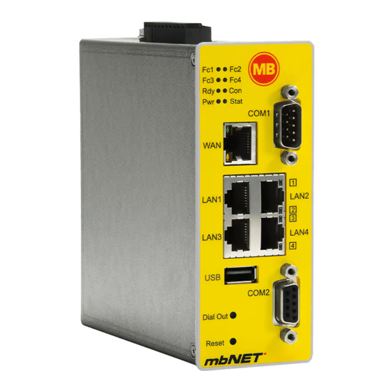
Page 9: Displays, Controls And Connections
5 Displays, controls and connections X1 | X2 I4 I3 I2 I1 P M O2 O1 Power supply connection 10-30V DC – 0V DC connection Digital input I4 (10-30V) Digital input I3 (10-30V) Digital input I2 (10-30V) Digital input I1 (10-30V) Fuse-protection 10-30V DC 0V DC connection Digital output A2 COM1 Digital output A1 MDH814, MDH819, MDH834, MDH849, MDH850, MDH855, MDH858, MDH859... - Page 10 Label Status Description Router power source is switched off or router is not connected to LED off power source / power pack. (Power) LED on Power source is connected to terminal block and switched on. The Ready LED does this for approx. 35 seconds when the de- LED flashing vice is switched on. After this, flashing indicates boot sequence. This may take up to 90 seconds depending on the type of device. (Ready) LED on The router is ready. LED off Serial interface COM1 not receiving data. (Function 1) LED on Serial interface COM1 receiving data. LED off Serial interface COM1 not sending data. (Function 2) LED flashing Serial interface COM1 sending data. LED off Serial interface COM2 not receiving data. Serial interface COM2 receiving data. (Function 3) LED flashing On if MPI: bus communication OK. LED off Serial interface COM2 not sending data. Serial interface COM2 sending data. (Function 4) LED flashing If MPI: bus transferring data.
- Page 11 Label Status Description LED off Router working without errors. Router error. Diagnostics under System Status (Error) LED on (see Status - System)� Router WAN port. (customer network, DSL modem ...) LED green Network connection available. lights WAN-LED LED flashing Network data transfer active. orange LAN 1 - 4 Local network ports (e.g. machine network). LED green Network connection available. LAN-LED lights 1- 4 LED flashing (Dual LED) Network data transfer active. orange Portable USB drive port.
-
Page 12: First Time Operation
6 First time operation Connect, depending on device type, an antenna, and insert a SIM card. Before connecting the router to a network or PC, first ensure that it is properly connected to a power supply, otherwise it may cause damage to other equipment. • Connect equipotential bonding to the grounding lug on the router’s top panel. I4 I3 I2 I1 P M O2 O1 | | X2 | • Connect the (10-30V DC) power supply to the X1 terminal of the router. Achten Sie auf die richtige Polung! ◦ After switching on the supply voltage the Pwr LED lights up and the device performs a system check. ◦ After about 25 sec., both LED Pwr and LED Err light up. ◦ After another 25 sec., LED Err turns off and the LED Rdy flashes. ◦ After a total of about 90 sec., both LED Pwr and LED Rdy light up. T + 25 Sek. T + 50 Sek. T + 90 Sek. -
Page 13: Initial Configuration
7 Initial configuration Requirements: • You have a user account on the web portal mbCONNECT24 V 1.7.x or the Remote Service Portal RSP RSP mbCONNECT24 V 2.x If you do not have a user account on mbCONNECT24, please contact your system administrator or authorized sales partner. For more information about mbCONNECT24 see www.mbconnectline.com in our Download Portal.. • Windows PC with remote client software mbDIALUP * installed . With mbDIALUP you establish a secure VPN connection to mbCONNECT24� * The latest version can be downloaded on www.mbconnectline.com Generally following procedure applies: • Add the mbNET in the portal mbCONNECT24 as a new device. • Enter the necessary basic data, so that the device can connect to the portal (for example, device name, network settings, connection information, etc.). • Transfer the device configuration from the portal into the mbNET� • After the mbNET has been connected to the portal, it can be configured completely there� More information about configuring devices, see the mbNET Manual (download under www.mbconnectline.com) or in the mbCONNECT24 online help. - 13 -... -
Page 14: Initial Configuration Via Mbconnect24 V 1.7
7.1 Initial confi guration via mbCONNECT24 V 1.7 7.1.1 Login mbCONNECT24 mbDIALUP ADVICE: Change unconditionally and without delay the default login information! 7.1.2 Create a device For the initial confi guration following information / settings are necessary: • Description: Device Name und Type • Network: LAN IP and LAN Netmask bzw. WiFi settings • Internet: WiFi WAN Settings - 14 -... -
Page 15: Creating The Configuration
Save your settings� Click 7.1.3 Creating the Confi guration Confi guration Click mbconnect24.mbn Then click in the Device Administration on the disk icon and select “Download to PC“ option. Save the confi guration fi le on a USB stick - directly in the root directory. - 15 -... -
Page 16: Transfer Configuration To The Mbnet
7.1.4 Transfer confi guration to the mbNET When the mbNET is ready to operate, insert the USB stick into the USB port of the device. As soon the mbNET recognizes the confi guration fi le, both LED Fc1 + LED Fc2 are fl ashing� COM1 Press immediately and hold down the Dial Out Dial Out button until LED Fc3 fl ashes � LAN1 LAN2 Release the Dial Out button � LAN4 LAN3 LAN3 Dial Out The settings from mbCONNECT24 are now automatically copied to the mbNET and the device... -
Page 17: Initial Configuration Via Rsp Mbconnect24 V 2.X
7.2 Initial confi guration via RSP mbCONNECT24 V 2.x 7.2.1 Login mbCONNECT24 mbDIALUP ADVICE: Change unconditionally and without delay the default login information! Navigation: Administration > Users 7.2.2 Creating a project Navigation: Administration > Projects In the project overview, click the plus and assign the next screen a Project Name (all other inputs / information can be made up later)� - 17 -... -
Page 18: Create A Device
7.2.3 Create a device Navigation: Administration > Projects > Project Alpha (selected project) In the selected project, click the plus and select “Create new device“. For the basic confi guration, you only need to select your “Device Type“ and enter a unique device „Name“. You can create your own name for the Device. Following numbers and letters are allowed: 0 to 9, A to Z, a to z (avoid blanks). After saving your settings you will be automatically redirected to the device settings� For the initial confi guration here the “Interfaces“ menu is relevant. - 18 -... -
Page 19: Configuring The Device (Connection Data)
7.2.4 Confi guring the device (connection data) Navigation: Administration > Projects > Project Alpha (selected project) > NewDecice (selected device) Here the following menus are relevant for the initial confi guration: • LAN (all devices) Make sure that the LAN IP and the WAN IP are in diff erent address ranges. • WiFi (devices with WiFi modem) • Internet (all devices) For the initial confi guration, it is advisa- ble to select “Always“... -
Page 20: Creating A Configuration
7.2.5 Creating a confi guration Navigation: Administration > Projects > Project Alpha (selected project) > NewDecice (selected device) After entering all necessary data, you must transfer the confi guration to the mbNET. Therefor connect an USB stick to your confi guration PC (the USB stick must have the fi le format FAT!)� and select “Download to PC“� Click the Sync icon The confi guration fi le “mbconnect24.mbn“ can now be downloaded to the USB stick. IMPORTANT: The downloaded confi guration fi le “mbconnect24.mbn“ must not be renamed and must be in the root directory of the USB stick! - 20 -... -
Page 21: Transfer Configuration To The Mbnet
7.2.6 Transfer confi guration to the mbNET When the mbNET is ready to operate, insert the USB stick into the USB port of the device. As soon the mbNET recognizes the confi guration fi le, both LED Fc1 + LED Fc2 are fl ashing� COM1 Now press and hold down the Dial Out button Dial Out until LED Fc3 fl ashes � LAN1 LAN2 Release the Dial Out button � LAN4 LAN3 LAN3 Dial Out The settings from mbCONNECT24 are now automatically copied to the mbNET and the device... -
Page 22: Access The Web Interface Of The Mbnet
8 Access the web interface of the mbNET On the web interface of the mbNET a Status page and a Diagnostic page is available. On the Status page, five steps with additional information are displayed, which must be run through when connecting the mbNET with the portal. The Diagnostic page helps you in case of a failed connection establishment in trobleshooting. Requirements: • The configuration PC and the mbNET must be in the same IP address range. Depending on the LAN IP that you assigned to the device in the portal, you may need to assign the configuration PC to the same address range. If you assigned the mbNET e.g. the LAN IP 192.168.2.200, you need the configuration PC to assign the same address range (192.168.2.X). This applies to both the IP address and subnet mask. • The mbNET must be accessible via the LAN interface of the configuration PC. Start a browser and enter the LAN IP you have assigned in the portal to the mbNET� To log on to mbNET enter the following data: Username: admin Password: (no password needed) - 22 -... -
Page 23: Device State
8.1 Device State After a successful login you will see on the status page the “Device State“� Among other things, the five steps are dis- played that are required so that the device can connect to the portal. = everything OK = processing = Error Click on the icon to the right of each progress to get details / information about this step. If all five steps have been completed successfully, the mbNET is connected to the portal mbCONNECT24� - 23 -... -
Page 24: 8�2 Diagnostics
8.2 Diagnostics In case of a failed connection setup, the diagnostic page supports for trobleshooting. The respective result of the individual, independent functions / commands you need, inter alia in case of support� 9 Loading the factory settings Before you reset the device to its factory settings, note the following: • The IP address will reseted to the default (192.168.0.100). You may need to modify the network settings of the confi guration PC accordingly. • There must be no USB fl ash drive be connected to the device. • The device must be operational (LED Pwr + Rdy light up). - 24 -... - Page 25 Press and release the Reset button and wait Reset (approx. 30 seconds) until LED Rdy flashes � Then press the Dial Out button immediately Dial Out and hold it pressed until LED Fc4 lights � COM1 Press the Dial Out button again Dial Out => LED Fc3 lights up � LAN1 LAN2 Press the Dial Out button again Dial Out => LED Fc2 lights up � LAN4 LAN3 Press one last time the Dial Out button COM2 Dial Out => LED Fc2, Fc3 and Fc4 are off - Dial Out...
-
Page 26: Factory Settings On Delivery
(MDH800 – MDH859) is in complies Fernwartungssysteme with the essential requirements and other relevant pro- Winnettener Str. 6 visions of directives 2014/35/EU and 2014/53/EU. The 91550 Dinkelsbühl complete declaration of conformity can be found at: Germany www.mbconnectline.com + 49 (0) 700 / MBCONNECT + 49 (0) 700 / 62 26 66 32 www.mbconnectline.com © MB CONNECT LINE 2017 - 26 -...
Need help?
Do you have a question about the mbNET Series and is the answer not in the manual?
Questions and answers