Table of Contents
Advertisement
Advertisement
Table of Contents

Related Manuals for ATEQ F620


Summary of Contents for ATEQ F620
- Page 1 ATEQ F620 Quick Start Guide...
-
Page 2: Table Of Contents
2 / 02 Safety advisory / Warranty Good practices and safety instructions Air quality requirements Preamble ATEQ F620, a universal leak tester Leak test Principle of a cycle Your ATEQ F620 Front panel Connectors on the back panel (with all options) - Page 3 ATEQ Manufacturer Plants - Measurement Solution, Global Leader. 3 / 46 ATEQ info@ateq.com T.: +33 1 30 80 1020 15, rue des Dames, Z.I. ateq.com F.: +33 1 30 54 1100 78340 LES CLAYES-SOUS-BOIS FRANCE ATEQ K.K. info@ateq.co.jp T.: +81 566-84-4670 3 –...
-
Page 4: Safety Advisory / Warranty
Recommendations for the test environment Keep the test area as clean as possible. Recommendations for operators ATEQ recommends that the operators who use the devices have training and a level of qualification that correspond to the job to perform. General recommendations —... -
Page 5: Air Quality Requirements
For this purpose we strongly recommend that a suitable airtight filter is installed between the part under test and the instrument. ATEQ recommends the following characteristics for the air supplied into the device. Air characteristics ISO standard 8573 class Grain size and concentration 0.1 μm and 0.1 mg/m3... -
Page 6: Preamble
Preamble 6 / 46 ATEQ F620, A UNIVERSAL LEAK TESTER ATEQ F620 is a leak detector that tests the airtightness of parts. ATEQ F620 can memorise 128 different test programs. QSG_F620.283.00_EN_01 / 2019-02-20... -
Page 7: Leak Test
LEAK TEST Direct measurement principle 7 / 46 The part under test 3 and the reference part 5 are filled to an identical pressure. A differential sensor 4 measures the pressure variation between the part under test 3 and the reference part 5. In some applications, the reference part can be replaced by a cap. -
Page 8: Principle Of A Cycle
PRINCIPLE OF A CYCLE The measurement cycle is made of 4 main phases: fill, stabilization, test, dumping. 8 / 46 Pressure Time Cycle start Cycle end Waiting phase Fill phase Stabilization phase Test Dumping QSG_F620.283.00_EN_01 / 2019-02-20... -
Page 9: Your Ateq F620
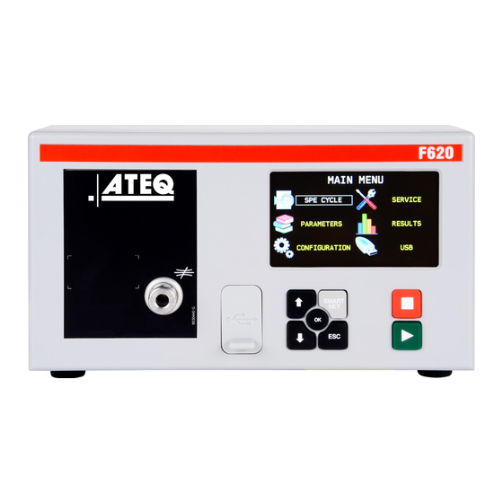
Your ATEQ F620 9 / 46 FRONT PANEL The user interface is located on the front panel. Display Cycle keys Navigation keys USB connectors Quick connector Mechanical Regulator For more information, refer to User interface QSG_F620.283.00_EN_01 / 2019-02-20... -
Page 10: Connectors On The Back Panel (With All Options)
CONNECTORS ON THE BACK PANEL (WITH ALL OPTIONS) 10 / 46 QSG_F620.283.00_EN_01 / 2019-02-20... - Page 11 Name Description Analog outputs - pressure and leak (option) 11 / 46 Fieldbus connector Extender (not operational) Program selection extension connector (option) Printer RS232 connector / Modbus (option) or Profibus (option) Reference part connector Not used Exhaust output Differential sealed part connector (option) Input connector to the air filter (valves or regulator air supply) Pilot pressure input or test pressure input (according configuration)
-
Page 12: Power Supply Connectors
POWER SUPPLY CONNECTORS The device can be connected to an external power supply (24 V DC - 2 A) or provided with an internal power supply (100 / 240 V AC) (option). 12 / 46 External supply 24 V DC connector (J7) The device can be connected to a 24 V DC - 2 A power supply through a M12 4 pins type connector. - Page 13 Internal supply only 100 / 240 V AC connector (J7) (option) 13 / 46 The device can be connected to a 100 / 240 V AC power supply (option). This connector has a ON/OFF button. It is mandatory to connect the device to the ground with a good link to the ground, to protect against electric hazard or electrocution.
-
Page 14: Digital Links
DIGITAL LINKS PC USB connectors (on front face) 14 / 46 USB connectors can be used for connecting miscellaneous compatible USB devices. The USB connectors are located under the rubber cover 1 (see figure). Rubber cover USB connector to PC USB connector to USB key Do not connect two USB devices at the same time. - Page 15 VP (supply) Not used Data line B Not used Devicenet connectors (J5) (J6) (option) M12 type connector - 5 pins male connector (J5) (Devicenet input) For connection to others ATEQ devices. Pin number Signal Drain CAN_H CAN_L M12 type connector - 5 pins female connector (J6) (Devicenet output) For connection to others ATEQ devices.
- Page 16 Profinet connectors (J5 + J6) (option) M12 D coded type connector - 4 pins female connector (J5 + J6) 16 / 46 Pin number Signal Ethernet Tx + (Transmit Data +) Ethernet Rx + (Receive Data +) Ethernet Tx - (Transmit Data -) Ethernet Rx - (Receive Data -) Ethernet connector (J5 + J6) (option) Standard connection Ethernet TCP / IP protocol.
-
Page 17: Analog Outputs
ANALOG OUTPUTS M12 type connector - 8 pins female connector (J1) 17 / 46 Pin number Signal Ground Pressure 0 - 10 V DC Pressure Ground Pressure (Diff) 0 - 10 V DC Pressure (Diff) Signal contact event Ground contact event Other options Other options QSG_F620.283.00_EN_01 / 2019-02-20... -
Page 18: Digital Inputs/Outputs
DIGITAL INPUTS/OUTPUTS The 24V DC power supply for the digital inputs can be provided by 2 means: — The internal power supply of the device (0.3A max) 18 / 46 — An external power supply provided by the customer. Inputs default mode is PNP. NPN mode is available on request. Relay board connector (J11) (option) Characteristics —... - Page 19 Pin number Inputs / outputs Description Output Warning Output End of cycle 19 / 46 Ground The device can be energized through the J11 connector of the relay board (except if internal supply option): 0 V to the pin 16 24 V DC to the pin 2 or 4. Program selection extension connector (J10) (option) The J10 connector is an extension of the J11 connector that enables the selection of 128 programs.
- Page 20 Program selection (J11 and J10) The connectors J11 and J10 (option) enable you to select a program from digital inputs. Combinations of connector pins to activate for program selection 20 / 46 Program number Pin 5 Pin 6 Pin 7 Pin 8 Pin 9 Pin 1...
- Page 21 Valve codes and auxiliary outputs board connector (J9) (option) Characteristics 21 / 46 — Outputs: 24 V DC - 100 mA max per output. • — Inputs: Activation: + 24 V DC. • Pin number Inputs / outputs Description + 24 V DC Common (outputs 1, 2,3) Output 1 Open collector...
-
Page 22: Pneumatic Connectors
22 / 46 Pneumatic supply The pneumatic supply has to meet specific requirements recommended by ATEQ. Refer to Good practices and safety instructions section. A specific filter may be necessary. The air is supplied via the filter located on the back panel of the device. - Page 23 Quick connector (on front face) (option) Use this function to check the calibration. 23 / 46 As this connector is part of the measurement circuit, all its connections must be air tight. Test and reference outputs The outputs enables parts to be connected (test and reference) Test connector Reference connector Not used...
- Page 24 Other inputs / outputs The outputs enables parts to be connected (test and reference) Pilot pressure input or test pressure 24 / 46 input (according configuration) Test pressure output (indirect mode) (from 0.5 to 2 MPa (72.5 to 290 PSI) according configuration) Pneumatic input or output (according configuration) Exhaust output (indirect mode)
-
Page 25: Pneumatics Configuration
PNEUMATICS CONFIGURATION 25 / 46 Direct mode - Low range Pressure: from 0 to 500 kPa (72.5 PSI) Connections Connection Option / description 6 to 1 Connection of the reference output to the reference part 5 to 4 Connection of the test output to the part under test Air supply to 2 Connection of the air supply to the filter input (0.6 MPa (87 PSI)) Vacuum to 3... - Page 26 Direct mode - Medium range Maximum pressure: 1 MPa (145 PSI) 26 / 46 Connections Connection Option / description 6 to 1 Connection of the reference output to the reference part 5 to 4 Connection of the test output to the part under test Regulator air supply to 2 Connection of the regulator air supply to the filter input (1.2 MPa (174 PSI))
- Page 27 Direct mode - High range Maximum pressure: 2 MPa (290 PSI) 27 / 46 Connections Connection Option / description 6 to 1 Connection of the reference output to the reference part 5 to 4 Connection of the test output to the part under test Air supply to 2 Connection of the air supply to the filter input (0.6 MPa (87 PSI)) Regulator air supply to 3...
- Page 28 Indirect mode Maximum pressure: 1 MPa (145 PSI) 28 / 46 Connections Connection Option / description Connection of the regulator air supply to the filter input (1.2 MPa Regulator air supply to 1 (174 PSI)) Air supply to 2 Connection of the air supply (0.6 MPa (87 PSI)) 3 to 5 Connection of the regulator output to the part under test 8 to 6...
- Page 29 Direct mode - Sealed part test Pressure: from 0 to 500 kPa (72.5 PSI) 29 / 46 This configuration can be used for test of small test part volumes. Protect volumes and pipes from air blowing and temperature variations. Connections Connection Option / description 9 to 1 Connection of the reference output to the reference part 8 to 7...
- Page 30 Direct mode - Sealed part differential volume test Pressure: from 0 to 500 kPa (72.5 PSI) 30 / 46 Connections Connection Option / description 2 to 1 Connection of the reference output to the reference part 9 to 8 Connection of the test output to the part under test 8 Or 9 to 11 Connection of the test output to the bell 11 including the part under test 10 for differential volume test...
- Page 31 Direct mode - Option test check by pressure drop Pressure: from 0 to 500 kPa (72.5 PSI) 31 / 46 Connections Connection Option / description 2 to 1 Connection of the reference output to the reference part 7 to 6 Connection of the test output to the part under test 6 Air supply to 3 Connection of the air supply to the filter input (0.6 MPa (87 PSI)) 4 to 5...
-
Page 32: User Interface
User interface 32 / 46 OVERVIEW The user interface comprises a display and user keys located on the front panel. Display Cycle keys Navigation keys KEYS Cycle keys The cycle keys are used to start and to stop a measurement cycle. Name Function Start... -
Page 33: Display
Navigation keys The navigation keys are used to select menus/options and change parameter values. 33 / 46 Name Function Up key Scrolls up or increases numerical values. Down key Scrolls down or decreases numerical values. Returns to the MAIN MENU screen or opens menus and options, validates parameters. - Page 34 The Measurement cycle screen The Measurement cycle screen displays the different values of the current test (or last one). Test pressure measurement 34 / 46 Test result or step phase Test reject value TEST 0.742 Vertical line test result Remaining time of the current phase or ready status 1.3 s Pr 1...
-
Page 35: Starting Up
Starting up 35 / 46 POWER UP 1. Make sure that all the necessary connections are in place. Electrical: such as power supply, inputs/outputs Pneumatic: including line pressure supply 2. Power up your device. When power-up is completed, the Program screen is Pr 001 displayed with last program used on screen. -
Page 36: Modifying A Parameter
CONFIGURING THE ASSOCIATED MEASUREMENTS 3. Select a measurement type and press The parameters of the selected measurement type are 36 / 46 PARAM / Pr 001 TYPE : LEAK TEST displayed. COUPL. A 0.0 s FILL TIME 2.0 s 4. Define the measurement cycle parameters. STAB TIME 2.0 s TEST TIME... -
Page 37: Selecting A Program
SELECTING A PROGRAM If necessary, you can select another program. 37 / 46 1. Press up/down Pr 001 LEAK TEST STARTING AND STOPPING CURRENT CYCLE Use the front panel keys to start/stop a measurement cycle. With the desired program displayed on the Program screen: STARTING A MEASUREMENT CYCLE 1. -
Page 38: User Adjustments
User adjustments 38 / 46 OPTIONS OF THE MENUS Different menus are accessible on the MAIN MENU screen. For more information, refer to the Reference Manual. SPE CYCLE menu Use this menu to carry out specific procedures necessary to ensure the proper operation of specific measurement cycles (for example, adjustment of pressure regulator). - Page 39 TO START SPECIAL CYCLES... 1. On the SPECIAL CYCLE MENU screen, select a 39 / 46 cycle, and press to validate. 2. Press Start to start the cycle. 3. To stop the current cycle press Reset PARAMETERS menu Use this menu to configure the measurement cycle associated to each test program. PARAM / Pr 001 TYPE : LEAK TEST COUPL.
- Page 40 Label Parameter Description PRE-FILL Pre fill time Time to pressurise the part under test (Pre fill function) 40 / 46 REJECT CALC. Reject calculation Define raw unit to calculate flow unit (Flow unit) Set FILL Set fill Fill pressure instruction (Fill function or electronic pressure regulator) Set PreFILL Pre fill pressure...
- Page 41 Label Function Description REF. VOLUME Reference volume Adjust the reference volume value with flow units only 41 / 46 REWORK LIMIT Rework limits Additional levels for specific reworkable parts Sd Part Sealed part Several optional ways to test sealed parts SD PART 2 SD PART 3 SEALED DIFF...
- Page 42 CONFIGURATION menu Use this menu to configure your ATEQdevice. 42 / 46 MAIN /CONFIGURATION LANGUAGE PNEUMATIC AUTOMATISM SECURITY MISCELLANEOUS Label Function Description LANGUAGE Language Selection of the language displayed on the screen PNEUMATIC Pneumatics Configuration of the pneumatics functions of the device > AUTO VOL Configuration of volume calculation for automatic program selection (option)
- Page 43 SERVICE menu Use this menu to do the maintenance of your device (status check, internal tests...). 43 / 46 MAIN /SERVICE CAN STATUS I/O STATE VALVE COUNTER DEVICE INFOS SERVICE CYCLES RESET PARA Label Function Description CAN STATUS Internal network state State of the internal network of the device I/O STATE Inputs/outputs state...
- Page 44 USB menu This section describes save and restore parameters on an external USB device. 44 / 46 MAIN /USB Save parameters Restore parameters Label Description Save parameters Save parameters on an external USB memory device for restoring later Restore parameters Restore parameters from an external USB memory device QSG_F620.283.00_EN_01 / 2019-02-20...
-
Page 45: Specifications
Specifications 45 / 46 CHARACTERISTICS Technical characteristics of the device. Main characteristics Characteristics Values Case dimensions: Height x Width x Depth 150 x 250 x 270 mm (5.91 x 9.84 x 10.63") Overall dimensions 150 x 250 x 360 mm (5.91 x 9.84 x 14.17") Format Half 19-inch rack Mass... - Page 46 46 / 46 QSG_F620.283.00_EN_01 / 2019-02-20...
Need help?
Do you have a question about the F620 and is the answer not in the manual?
Questions and answers