Table of Contents
Advertisement
Advertisement
Table of Contents

Related Manuals for ATEQ F6 Profinet Series


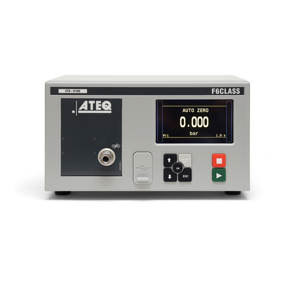
Summary of Contents for ATEQ F6 Profinet Series
- Page 1 F6 Series – Profinet Manual...
- Page 2 Basic notions ..........................5 Hardware installation Hardware configuration ........................ 7 Cabling ............................8 Configuration of the ATEQ device (slave) Setup of the station name ......................9 Setup of the Profinet configuration mode ................... 10 Setup of the IP address ....................... 11 Configuration of the master Installation of the Profinet module .....................
- Page 3 ATEQ Manufacturer Plants – Measurement Solution, Global Leader 2 / 75 ATEQ 15, rue des Dames, Z.I. info@ateq.com T.: +33 1 30 80 1020 78340 LES CLAYES-SOUS-BOIS ateq.com F.: +33 1 30 54 1100 FRANCE ATEQ K.K. 3 – 41 ATEQ Building, Ikehata info@ateq.co.jp...
- Page 4 ATEQ is at your disposal for any information concerning the use of the device under maximum safety conditions. We draw your attention to the fact that ATEQ cannot be held responsible for any accident related to a misuse of the measuring instrument, the workstation or non-compliance of the installation with safety rules.
- Page 5 Preamble INTRODUCTION This manual intends to help you for the configuration and the use of your ATEQ F6 device on the 4 / 75 Profinet network. For more information on your ATEQ equipment, refer to the Quick Start Manual. FG_F6_PROFINET_EN_04 / 2020-06-17...
- Page 6 Long format (Signed Double word) A Long format data is coded with two words (of 16 bits). In the memory range of the ATEQ device or when they are transmitted, both words are coming in the following order: — The first word is the least significant word —...
- Page 7 Numerical value All the numerical values are treated with the Long format with fixed comma (10 Thus, their value is expressed in thousandths of unit. So, this value must be multiplied by 1000 to get the value in units. For example, a value of 207055 represents 207.055. So, any numerical value must be divided by 1000 to get the real value: —...
- Page 8 Hardware installation HARDWARE CONFIGURATION Connect your ATEQ equipment to the Profinet fieldbus using its Profinet connectors and compatible 7 / 75 cables. Your device has a Profinet internal board and two Profinet connectors. The Profinet internal board is located inside your device. Two versions are available: —...
- Page 9 CABLING M12 - RJ45 cable Cable with male M12 D coded type connector and an RJ45 connector (4 or 8 pins) 8 / 75 Male M12 Pin RJ45 - 4 pins Pin RJ45 - 8 pins Pin Wire color Signal number number number...
- Page 10 Use this procedure to set the name and the configuration mode of your device. 9 / 75 This configuration can be done with the front panel of your ATEQ device or with the ATEQ Fieldbus Configurator software. SETUP OF THE STATION NAME The station name must be the same on slave and master.
- Page 11 40h-5Fh Exchange zone: cycle result reading or 10 parameters management 60h-FFh Exchange zone: cycle result reading or 20 parameters management From the MAIN MENU screen of your ATEQ device: ➢ CONFIGURATION ➢ AUTOMATISM ➢ FIELDBUS ➢ ACCESS FG_F6_PROFINET_EN_04 / 2020-06-17...
- Page 12 — IP: IP address 11 / 75 — SM: Network mask — GW: Gateway address From the ATEQ device From the MAIN MENU screen of your ATEQ device: ➢ CONFIGURATION ➢ AUTOMATISM ➢ FIELDBUS From the ATEQ Fieldbus Configurator software...
- Page 13 12 / 75 Identification of the version of the Profinet module You can identify the hardware configuration using your ATEQ device or using a fieldbus configuration software. For the installation and configuration of the Profinet module, you have to select the component that corresponds to the firmware (see Configuration files).
- Page 14 Configuration files to use for the configuration of the master instrument. Profinet hardware and software compatibilities The table below gives the configuration file to use according the hardware reference of the Profinet 13 / 75 internal board of your ATEQ device (Hilscher hardware reference). Profinet Hilscher Hilscher...
- Page 15 SELECTION OF THE MASTER CARD The screenshots used in this manual correspond to the ATEQ Fieldbus Configurator software. Nevertheless, you may use your own software to configure the master. From the Device Assignment screen, select the master card: 14 / 75...
- Page 16 SETUP OF THE STATION NAME The screenshots used in this manual correspond to the ATEQ Fieldbus Configurator software. Nevertheless, you may use your own software to configure the master. Select the Device Table screen to set up the station name of the slave instrument: 15 / 75 The station name must be the same on slave and master.
- Page 17 SETUP OF THE IP ADDRESS The screenshots used in this manual correspond to the ATEQ Fieldbus Configurator software. Nevertheless, you may use your own software to configure the master. Setup of the IP address of the master 16 / 75...
- Page 18 Setup of the IP address of the slave Select the Scanlist screen to set up the IP address of the slave instrument: 17 / 75 FG_F6_PROFINET_EN_04 / 2020-06-17...
- Page 19 SETUP OF THE PROFINET CONFIGURATION MODES Five configuration modes are available according to the bytes number available (see Configuration of the ATEQ device (slave)). Setup of the Standard mode (normal) 18 / 75 The parameters configuration must be like the following ones:...
- Page 20 Setup of the Standard less mode The parameters configuration must be like the following ones: Input_Data (IB) 96 bytes total: IB = 32 bytes IB = 64 bytes Output_Data (QB) 96 bytes total: QB = 32 bytes 19 / 75 QB = 64 bytes FG_F6_PROFINET_EN_04 / 2020-06-17...
- Page 21 Setup of the Medium more mode The parameters configuration must be like the following ones: Input_Data (IB): IB = 64 bytes Output_Data (QB): QB = 64 bytes 20 / 75 FG_F6_PROFINET_EN_04 / 2020-06-17...
- Page 22 Setup of the Medium mode The parameters configuration must be like the following ones: Input_Data (IB): IB = 32 bytes Output_Data (QB): QB = 32 bytes 21 / 75 FG_F6_PROFINET_EN_04 / 2020-06-17...
- Page 23 Setup of the Light mode The parameters configuration must be like the following ones: Input_Data (IB): IB = 16 bytes Output_Data (QB): QB = 16 bytes 22 / 75 FG_F6_PROFINET_EN_04 / 2020-06-17...
- Page 24 Functional description of an ATEQ device INTRODUCTION 23 / 75 — R/W*: reading and writing — W*: writing only — R*: reading only FG_F6_PROFINET_EN_04 / 2020-06-17...
- Page 25 Write table Writing table structure 0x00 Commands 24 / 75 0x01 0x02 Reserved 0x04 0x06 The program number (Running and Edit) Special cycle 0x09 0x0A Reserved 0x1F 0x20 Exchange table: Config Bits or Functions Bits or Parameters FG_F6_PROFINET_EN_04 / 2020-06-17...
- Page 26 Details writing table structure Address (bytes) Description Bit 0 = 1 > Reset (stop the current cycle). Bit 1 = 1 > Start (starting a test cycle). 25 / 75 Bit 2 = 1 > Special cycle (start a special cycle, example: regulator adjust). Bit 3 = 1 >...
- Page 27 Read table Reading table structure 0x00 State of the unit: 26 / 75 Echo / Error code command Status Current program Number of results available 0x0F Program step 0x10 Real time measurements. 0x1F 0x20 Exchange table: FIFO Results or Last Result or Parameters FG_F6_PROFINET_EN_04 / 2020-06-17...
- Page 28 Results status: (@: 00h – 0Fh) Echo: Acknowledgement of delivery of the master command allowing to determinate in which state is the slave (current command or command realised). Error code: In case of command execution error, the corresponding command error bit is activated. 27 / 75 Address (bytes) Description...
- Page 29 Address (bytes) Description Bit 0 = 1 > Pass part. (OK) Bit 1 = 1 > Fail test part. (NOK) Bit 2 = 1 > Fail reference part. (NOK) Bit 3 = 1 > Alarm. Bit 4 = 1 > Pressure error. 28 / 75 0Ch –...
- Page 30 Real time measurements: (@: 10h – 1Fh) Description Address (bytes) Pressure current value 10h – 13h Example: reading of 524000 (7FEE0h) = 524 x 1000, thus the real value is 524. 29 / 75 Pressure unit code Example: reading 6000 (1770h) = 6 x 1000, thus the value is 6 which corresponds to 14h –...
- Page 31 Reminder: "h" indicates a hexadecimal code, "(d)" indicates a decimal code. ATEQ device using Base procedure for using an ATEQ instrument. 30 / 75 If the number of results in the FIFO = 0, the results are erratic, do not read them.
- Page 32 Fieldbus progress chart 31 / 75 FG_F6_PROFINET_EN_04 / 2020-06-17...
- Page 33 CONFIGURATION General configuration Table of the configuration / extended menus bits 32 / 75 Reminder: “h” indicates a hexadecimal code, “(d)” indicates a decimal code. The bits below are mostly present in the CONFIGURATION or More functions... menus. They are only used to allow the access to other parameters according to the configuration, depending on the configuration, these are active or not.
- Page 34 Mask Word Bit n° Meaning Menu Hexa 0001 Calibration check. +Funct 0002 Valve codes (output codes). +Funct 33 / 75 0004 Sealed component (Leak unit always +Funct PA, not changeable). 0008 Stamping. +Funct 0010 Reserved. 0020 N test. +Funct 0040 Reserved.
- Page 35 Mask Word Bit n° Meaning Menu Hexa 0001 Unit type. +Funct 0002 Automatic reset piezo 2. Conf 0004 Reserved. 34 / 75 0008 Electronic regulator mode. Conf 0010 Auxiliary codes activation. +Funct 0020 Filtering. +Funct 0040 Reserved. 0080 Quick automatic reset activation. Conf 0100 Permanent electronic regulator.
- Page 36 Mask Word Bit n° Meaning Menu Hexa 0001 Buzzer function. +Funct 0002 Long test (x100) function. +Funct 0004 Permanent blowing. Conf 35 / 75 0008 Sealed Diff component function. +Funct 0010 Test or Ref Mode. +Funct 0020 Display optional. +Funct 0040 Pressure Drop.
- Page 37 Reading of the configuration / extended menu bits Master Slave — Activate the “Read extended menu bits” command: Write at the address 00(h), the value 0200(h) Byte 0 = 00(h) 36 / 75 Byte 1 = 02(h) (Bit 1 = 1) Acknowledgement Command echo: —...
- Page 38 Writing of the configuration / extended menu bits Master Slave — Write the extended menu bits at the address 20(h) — Activate the “Write extended menu bits” command: 37 / 75 Write at the address 00(h), the value 0800(h) Byte 0 = 00(h) Byte 1 = 08(h) (Bit 3 = 1) Acknowledgement Command echo:...
- Page 39 Program Program selection command on the ATEQ device Master Slave — Write 1 word at the address 06(h) corresponding to the program number to be selected: 38 / 75 @06(h) = 0001(h) (= program n°2) — Activate the “Program selection” command:...
- Page 40 Function Table of the function bits Table of the function bits per program. Reminder: “h” indicates a hexadecimal code, “(d)” indicates a decimal code. 39 / 75 The bits below are present in the FUNCTIONS menu of each program, if these have been previously validated in the More functions...
- Page 41 Mask Word Bit n° Meaning Menu Hexa 0001 External valve code 6 function. Funct 0002 Internal valve code 1 function. Funct 0004 Internal valve code 2 function. Funct 0008 Stamp function. Funct 40 / 75 0010 Pass part stamp function. Funct 0020 Fail test part stamp function.
- Page 42 Mask Word Bit n° Meaning Menu Hexa 0001 Start after reading bar code function. Funct 0002 ATR3 function. Funct 0004 Absolute value function. Funct 0008 Bypass valve function. Funct 41 / 75 0010 Reserved. 0020 Inverted sealed component function. Funct 0040 Inverted sealed component 2 function.
- Page 43 Mask Word Bit n° Meaning Menu Hexa 0001 Old Flow Calcultion. Funct 129>143 Reserved. Example: bit number 46 (Offset function) activated on 1, will put to "4000h" the value in the third 42 / 75 word. 4000h is equivalent to 16384 in decimal and 0100000000000000 in binary. In the Modbus frame, the words will follow as such: word 1 + word 2 + …..
- Page 44 Reading of the function bits Master Slave — Select the program number on which the functions bits have to be read — Activate the “Read functions bits” command: Write at the address 00(h), the value 0400(h) 43 / 75 Byte 0 = 00(h) Byte 1 = 04(h) (Bit 2 = 1) Acknowledgement Command echo:...
- Page 45 Writing of the function bits Master Slave — Select the program number on which the functions bits have to be read. — Write the functions bits at the address 20(h) — Activate the “Write functions bits” command: 44 / 75 Write at the address 00(h), the value 1000(h) Byte 0 = 00(h) Byte 1 = 10(h) (Bit 4 = 1)
- Page 46 Parameters Downloading of the parameters All the parameters values below have a tratment by the ATEQ device as Long format with fixed comma ). A Long is a two words set. 45 / 75 Identifier N° Meaning Value Hexa “FILL TIME”...
- Page 47 Identifier N° Meaning Value Hexa “Press. UNIT” 0035 Refer to Unit table. Pressure unit. “Test FAIL” 003C 0 > 9999 Natural reject value of the test part “TestREWORK” 46 / 75 003D 0 > 9999 Natural reject level of the test part in recovery “Ref.
- Page 48 Identifier N° Meaning Value Hexa ‘IN7:” Refer to the “Configurable input Function attributed to the entry of the special 0070 values” table at the end of this cycles (input 7) chapter “Set Blow” 0075 - 9999 > 9999 Permanent blowing pressure instruction. 47 / 75 “REJECT CALC.”...
- Page 49 Identifier N° Meaning Value Hexa “Volume UNIT” 00A1 Refer to Unit table. Volume unit. “NEXT PROG.” 00A4 1 > 128 Number of the following program in sequencing. “N. OF CYCLES”(PIEZO AUTO AZ menu) 48 / 75 00A5 0 > 9999 Number of cycles between two automatic reset.
- Page 50 Identifier N° Meaning Value Hexa “DUMP TIME” (AUTO VOL menu) 0165 0 > 650 seconds Dump time in program selection by volume function “PRESSU. VOL” (AUTO VOL menu) 0166 Internal volume in program selection by volume 0 > 9999 function 49 / 75 “Ref.
- Page 51 Identifier N° Meaning Value Hexa Supervision 0000 Printer 1000 “USB:” 017B Bar code 2000 USB mode (printer or supervision) Auto 3000 None 4000 50 / 75 “Press. UNIT“(Indirect menu) 017C Refer to Unit table Pressure unite for recovery test “TRANSF.TIME” (Sealed Diff menu) Sealed Diff, 0195 0 >...
- Page 52 Identifier N° Meaning Value Hexa “EXT. ACCES” Security by external access (Fieldbus/Modbus) Read/Write 0000 Reset value with Modbus: 01 E5 Read Only 1000 → Writing at address 0xC1E5 No Access 2000 Reset value with Fieldbus: 51 / 75 → Writing one word with ID = 0xC1E5 “OFFSET”...
- Page 53 F6 V2.XXX Input value Value code Input value Value code Program Selection 0000 Chck+Lrn Cust. Unit 24000 Diff Temp. Check (*) 8000 Atr Learning Cycle 25000 Direct P. Check (*) 9000 Sd Prt Pass Learn 26000 P1 Reg1 Check (*) 10000 Sd Prt Fail Learn 27000...
- Page 54 Unit table This list gives all the units used in the instrument in hexadecimal code. Unit code Unit Decimal Hexadecimal 0000 0000 53 / 75 1000 03E8 /min 2000 07D0 3000 0BB8 4000 0FA0 Calibrated Pascal (Pa) 5000 1388 Calibrated Pascal/second (Pa/s) 6000 1770 Pascal (Pa)
- Page 55 Unit code Unit Decimal Hexadecimal 62000 F230 Liter (l) 63000 F618 Inch 64000 FA00 Feet 68000 01 09A0 oz(US)/s 54 / 75 69000 01 0D88 oz(US)/mn 70000 01 1170 oz(US)/h 71000 01 1558 oz(UK)/s 72000 01 1940 oz(UK)/mn 73000 01 1D28 oz(UK)/h 74000 01 2110...
- Page 56 Reading of the parameters The reading of the parameters is carried out by data exchange in the corresponding area depending on the configuration mode of the slave. Each parameter is identified by one identifier. See identifiers tables. This table is an example based on the reading of two parameters: —...
- Page 57 Master Slave — Read the parameters at the address 20(h): Word 1 = identifier number of the first read parameter. Word 2 and Word 3 = first parameter value x1000 (long format). Word 4 = second identifier number of the read 56 / 75 parameter.
- Page 58 Writing of the parameters The writing of the parameters is carried out by data exchange in the corresponding area depending on the configuration mode of the slave. Each parameter is identified by one identifier. See identifiers tables. This table is an example based on the reading of two parameters: —...
- Page 59 Master Slave — Wait the end of the command: command echo = 0040(h) command error code ≠ FFFF(h) (end of command) — Deactivate the “Write parameters” command: Write at the address 00(h) the value 0000(h) Byte 0 = 00(h) (Bit 6 = 0) 58 / 75 Byte 1 = 00(h) The master instrument must always set to zero the command bit.
- Page 60 Reading of the program name Master Slave — Select the program whose name you want to read — Activate the “Read program name” command: Write at the address 00(h), the value 2000(h) Byte 0 = 00(h) 59 / 75 Byte 1 = 20(h) (Bit 5 = 1) Acknowledgement Command echo: —...
- Page 61 Writing of the program name Master Slave — Select the program whose name you want to modify — Write the program name of 12 characters/bytes maximum at the address 20(h). — 60 / 75 Activate the “Write program name” command: Write at the address 00(h), the value 4000(h) Byte 0 = 00(h) Byte 1 = 40(h) (Bit 6 = 1)
- Page 62 CYCLE Standard command cycle Start cycle command on the ATEQ device 61 / 75 Master Slave — Select the program you want to start — Activate the “Start” command: Write at the address 00(h), the value 0002(h) Byte 0 = 02(h) (Bit 1 = 1)
- Page 63 62 / 75 Start command = On Acknowledge by ATEQ = (Echo command = On) and (Error code command = FFFFh) Wait end of Start command = (Echo command = On) and (Error code command ≠ FFFFh) Start command = Off Acknowledge by ATEQ = (Echo command = Off) and (Error code command ≠...
- Page 64 Reset command on the ATEQ device Master Slave — Activate the “Reset” command: — Write at the address 00(h), the value 0001(h) Byte 0 = 01(h) (Bit 0 = 1) Byte 1 = 00(h) Acknowledgement 63 / 75 Command echo: —...
- Page 65 Special cycles Special cycle table Write the identifier number of the wanted special cycle at the address 04(h) and its instruction if necessary. @08(h) = identifier number of the special cycle 64 / 75 @09(h) = instruction for the special cycle Numb Special cycle Numb...
- Page 66 Auto-zero on the ATEQ device Master Slave — Select the program on which you want to make the auto zero — Write at the address 08(h) the identifier number of the special cycle for an auto zero — Activate the “Start” and the “Start special cycle”...
- Page 67 RESULTS FIFO results FIFO list results structure 66 / 75 At the end of each cycle, a result is stored as an array of 40 words contained in a FIFO of 8 results. This result includes the final state of the instrument (relays position, alarm signal, indicators state…), but also of the test (units, values measured for pressure and flow).
- Page 68 Words Meaning Type Bytes Coeff V2.xxx Only Pa – Pa/s Leak result low part word Long x1000 Pa – Pa/s Leak result high part word 27 - 36 Unused Atmospheric pressure in hPa low part word Long x1000 67 / 75 Atmospheric pressure in hPa high part word Temperature in °C low part word Long...
- Page 69 Step table This table represents the codes of the steps in the cycle. Code Steps Decimal Hexadecimal 0000 Pre-fill. 68 / 75 0001 Pre-dump. 0002 Sealed component fill. 0003 Sealed component stabilization. 0004 Fill. 0005 Stabilization. 0006 Test. 0007 Dump. 65535 FFFF No steps in progress.
- Page 70 Alarm codes table This list gives all the alarms in hexadecimal code. Identifier n° Alarm Decimal Hexadecimal 0000 No alarm. 69 / 75 0001 Pressure switched alarm (test pressure too high). 0002 Pressure switch (test pressure too small). 0003 Large leak on TEST (EEEE). 0004 Large leak on REF (MMMM).
- Page 71 Cycle results reading (last 8 results in FIFO) Master Slave — Read the number of available results in the FIFO at the address 08(h): 08(h) = 0000(h) → no results 08(h) > 0000(h) → results available — 70 / 75 Activate the “Read FIFO results”...
- Page 72 Reset FIFO results This command resets the 8 last cycle’s results available in the FIFO. Master Slave — Activate the “Reset FIFO results” command: Write at the address 00(h), the value 0080(h) Byte 0 = 80(h) (Bit 7 = 1) 71 / 75 Byte 1 = 00(h) Acknowledgement...
- Page 73 Last results Last results structure At the end of each cycle, the last result is as an array of 40 words. This result includes the final state of the instrument (relays position, alarm signal, indicators state…), but also of the test (units, values measured for the pressure and the flow).
- Page 74 Words Meaning Type Bytes Coeff V2.xxx Only Pa – Pa/s Leak result low part word Long x1000 Pa – Pa/s Leak result high part word 27 - 36 Unused Atmospheric pressure in hPa low part word Long x1000 73 / 75 Atmospheric pressure in hPa high part word Temperature in °C low part word Long...
- Page 75 Last results reading For using this function, it is important to: — Having done a start on the instrument before (“End of cycle” bit on in the relay status) — Not having done a reset of the FIFO 74 / 75 Master Slave —...
- Page 76 Real time Status and real time measures The real time measurement is used for display curve or values during the cycle and not for the final measurement. Do not take or use the final results in this section, it is just to see the status of the device for the “Cycle 75 / 75 end”...
Need help?
Do you have a question about the F6 Profinet Series and is the answer not in the manual?
Questions and answers