Table of Contents
Advertisement
Advertisement
Table of Contents

Related Manuals for ATEQ F28+


Summary of Contents for ATEQ F28+
- Page 1 ATEQ F28+ Quick Start Guide...
-
Page 2: Table Of Contents
2 / 02 Safety advisory / Warranty Good practices and safety instructions Air quality requirements Preamble ATEQ F28+, a universal leak tester Leak test Principle of a cycle Your ATEQ F28+ Front panel Connectors on the back panel (with all options) - Page 3 ATEQ Manufacturer Plants - Measurement Solution, Global Leader. 3 / 42 ATEQ info@ateq.com T.: +33 1 30 80 1020 15, rue des Dames, Z.I. ateq.com F.: +33 1 30 54 1100 78340 LES CLAYES-SOUS-BOIS FRANCE ATEQ K.K. info@ateq.co.jp T.: +81 566-84-4670 3 –...
-
Page 4: Safety Advisory / Warranty
Recommendations for the test environment Keep the test area as clean as possible. Recommendations for operators ATEQ recommends that the operators who use the devices have training and a level of qualification that correspond to the job to perform. General recommendations —... -
Page 5: Air Quality Requirements
For this purpose we strongly recommend that a suitable airtight filter is installed between the part under test and the instrument. ATEQ recommends the following characteristics for the air supplied into the device. Air characteristics ISO standard 8573 class Grain size and concentration 0.1 μm and 0.1 mg/m3... -
Page 6: Preamble
Preamble 6 / 42 ATEQ F28+, A UNIVERSAL LEAK TESTER ATEQ F28+ is a leak detector that tests the airtightness of parts. ATEQ F28+ can memorise 128 different test programs. QSG_F28+.394.00_EN_01 / 2019-02-25... -
Page 7: Leak Test
LEAK TEST Direct measurement principle 7 / 42 The part under test 3 and the reference part 5 are filled to an identical pressure. A differential sensor 4 measures the pressure variation between the part under test 3 and the reference part 5. In some applications, the reference part can be replaced by a cap. -
Page 8: Principle Of A Cycle
PRINCIPLE OF A CYCLE The measurement cycle is made of 4 main phases: fill, stabilization, test, dumping. 8 / 42 Pressure Time Cycle start Cycle end Waiting phase Fill phase Stabilization phase Test Dumping QSG_F28+.394.00_EN_01 / 2019-02-25... -
Page 9: Your Ateq F28
Your ATEQ F28+ 9 / 42 FRONT PANEL Name Description 24 V DV power supply Power on indicator Program selection extension connector Not used 0.6 MPa (87 PSI) air valve supply Regulated air pressure input 1 (option) Regulated air pressure input 2 (option) -
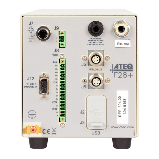
Page 10: Connectors On The Back Panel (With All Options)
CONNECTORS ON THE BACK PANEL (WITH ALL OPTIONS) 10 / 42 Name Description Reference part connector Not used Exhaust output Differential sealed part connector (option) Quick connector Calibration check by volume variation connector (option) Differential sealed part connector (option) Pneumatic output or A automatic connector (option) Test part connector Pressurization output QSG_F28+.394.00_EN_01 / 2019-02-25... -
Page 11: Power Supply Connectors
POWER SUPPLY CONNECTORS 24 V DC connector (J7) 11 / 42 The device can be connected to a 24 V DC - 2 A power supply through a M12 4 pins type connector. Pin number Signal + 24 V DC Not connected Ground: 0 V Not connected QSG_F28+.394.00_EN_01 / 2019-02-25... -
Page 12: Digital Links
DIGITAL LINKS PC USB connectors 12 / 42 USB connectors can be used for connecting miscellaneous compatible USB devices. The USB connectors are located under the rubber cover 1 (see figure). Rubber cover USB connector to PC (J2) USB connector to remote control (J3) Do not connect two USB devices at the same time. - Page 13 Profibus connector (JX) (option) Profibus - SubD 9 pins female connector 13 / 42 Profibus: SubD 9 pins female connector Pin number Signal PE (ground) Not used Data line A CNTR - A (repeater control signal) DGND (logic ground) VP (supply) Not used Data line B Not used...
- Page 14 Devicenet connectors (J5) (J6) (option) M12 type connector - 5 pins male connector (J5) (Devicenet input) 14 / 42 For connection to others ATEQ devices. Pin number Signal Drain CAN_H CAN_L M12 type connector - 5 pins female connector (J6) (Devicenet output) For connection to others ATEQ devices.
- Page 15 Ethernet connector (J5 + J6) (option) Standard connection Ethernet TCP / IP protocol. 15 / 42 One of these network protocols is available: — Ethernet IP — Profinet — Ethercat (J5 = Input J6 = Output). QSG_F28+.394.00_EN_01 / 2019-02-25...
-
Page 16: Digital Inputs/Outputs
DIGITAL INPUTS/OUTPUTS The 24V DC power supply for the digital inputs can be provided by 2 means: — The internal power supply of the device (0.3A max) 16 / 42 — An external power supply provided by the customer. Inputs default mode is PNP. NPN mode is available on request. Relay board connector (J8) (option) Characteristics —... - Page 17 Pin number Inputs / outputs Description Output Warning Output End of cycle 17 / 42 Ground Program selection extension connector (J9) The J9 connector is an extension of the J8 connector that enables the selection of 128 programs. Characteristics — Inputs Activation: + 24 V DC. •...
- Page 18 Program selection (J8 and J9) The connectors J8 and J9 enable you to select a program from digital inputs. Combinations of connector pins to activate for program selection 18 / 42 Program number Pin 5 Pin 6 Pin 7 Pin 8 Pin 9 Pin 1 Pin 2...
- Page 19 19 / 42 Pin number Inputs / outputs Description + 24 V DC Common (outputs 1, 2,3) Output 1 Open collector Output 2 Open collector Output 3 Open collector + 24 V DC Common (outputs 4, 5, 6) Output 4 Open collector Output 5 Open collector...
-
Page 20: Pneumatic Connectors
20 / 42 Pneumatic supply (on front panel) The pneumatic supply has to meet specific requirements recommended by ATEQ. Refer to Good practices and safety instructions section. The air is supplied via the 0.6 MPa (87 PSI) valve air supply input (1). - Page 21 Test and reference outputs The outputs enables parts to be connected (test and reference) Test connector 21 / 42 Reference connector Not used Exhaust output Pressurization output Metallic fitting available for test (1) and reference (2) connectors: — 2.7/4 mm — 3/5 mm —...
- Page 22 Differential sealed part connectors (option) (V1 and V2) External volume (closed tube) connection. Metallic fitting available for V1 and V2 22 / 42 connectors: — 2.7/4 mm Pneumatic output 0.6 MPa (87 PSI) (option) Pneumatic output or A automatic connector option. QSG_F28+.394.00_EN_01 / 2019-02-25...
-
Page 23: Pneumatics Configuration
PNEUMATICS CONFIGURATION 23 / 42 Direct mode - Test with external regulator From vacuum until 2 MPa (290 PSI) Connections Connection Option / description Air supply to 1 Connection of the air supply to the valve air supply input 3 to 2 Connection of an external regulator to the regulated air pressure input 1 5 to 4 Connection of an external regulator to the regulated air pressure input 2... - Page 24 Direct mode - Test with internal regulator From vacuum until 0.5 MPa (72.5 PSI) 24 / 42 Connections Connection Option / description Air supply to 1 Connection of the air supply to the valve air supply input Vacuum supply to 2 Connection of the vacuum supply to the regulated air pressure input 2 (option) 4 to 3 Connection of the reference output to the reference part...
- Page 25 Direct mode - Test with internal regulator From 0.6 MPa (87 PSI) until 2 MPa (290 PSI) 25 / 42 Connections Connection Option / description Air supply to 1 Connection of the air supply to the valve air supply input Air supply to 2 Connection of the air supply to the internal pressure regulator Connection of the air supply to the internal vacuum regulator Vacuum supply to 3...
- Page 26 Direct mode - Option test check by pressure drop Maximum pressure: 0.4 MPa (58 PSI) 26 / 42 Connections Connection Option / description Air supply to 1 Connection of the air supply to the valve air supply input 3 to 2 Connection of the reference output to the reference part 7 to 8 Connection of the test output to the part under test 4 to 5...
- Page 27 Direct mode - Sealed part differential volume test Maximum pressure: 1 MPa (145 PSI) 27 / 42 This configuration can be used for test of small test part volumes. Protect volumes and pipes from air blowing and temperature variations. Connections Connection Option / description Air supply to 1...
-
Page 28: User Interface (Remote Control)
The ATEQ F28+ can be set up and supervised using a remote control (option) connected 28 / 42 to the USB connector. The ATEQ F28+ can also be set up and supervised on a PC with a specific software (Winateq 300). OVERVIEW Display... -
Page 29: Keys
KEYS Cycle keys 29 / 42 The cycle keys are used to start and to stop a measurement cycle. Name Function Start On the Program screen, starts a measurement cycle and opens the Measurement cycle screen. Reset Stops the measurement cycle in progress and returns to the Program screen. -
Page 30: Display
DISPLAY The device uses three main screens. 30 / 42 The Program screen Use the Program screen to select a test program. Current program name (here NAME) NAME Current program number (here 001) Pr 001 Test type (here LEAK TEST) LEAK TEST Access at start-up of the instrument or by pressing several times Esc The Measurement cycle screen The Measurement cycle screen displays the different values of the current test (or last one). - Page 31 The MAIN MENU screen gives access to different sections for managing the device and the test parameters. Access: from the Program screen, press 31 / 42 MAIN MENU SPE CYCLE SERVICE PARAMETERS RESULTS CONFIGURATION Option Description SPE CYCLE Specific procedures necessary to ensure the proper operation of measurement cycles (for example, adjustment of a pressure regulator).
-
Page 32: Starting Up
Starting up 32 / 42 POWER UP 1. Make sure that all the necessary connections are in place. Electrical: such as power supply, inputs/outputs Pneumatic: including line pressure supply 2. Power up your device. When power-up is completed, the Program screen is Pr 001 displayed with last program used on screen. -
Page 33: Modifying A Parameter
CONFIGURING THE ASSOCIATED MEASUREMENTS 3. Select a measurement type and press The parameters of the selected measurement type are PARAM / Pr 001 33 / 42 TYPE : LEAK TEST displayed. COUPL. A 0.0 s FILL TIME 2.0 s 4. Define the measurement cycle parameters. STAB TIME 2.0 s TEST TIME... -
Page 34: Selecting A Program
SELECTING A PROGRAM If necessary, you can select another program. 34 / 42 1. Press up/down Pr 001 LEAK TEST STARTING AND STOPPING CURRENT CYCLE Use the front panel keys to start/stop a measurement cycle. With the desired program displayed on the Program screen: STARTING A MEASUREMENT CYCLE 1. -
Page 35: User Adjustments
User adjustments 35 / 42 OPTIONS OF THE MENUS Different menus are accessible on the MAIN MENU screen. SPE CYCLE menu Use this menu to carry out specific procedures necessary to ensure the proper operation of specific measurement cycles (for example, adjustment of pressure regulator). SPECIAL CYCLE MENU none Regulator adjust. - Page 36 PARAMETERS menu Use this menu to configure the measurement cycle associated to each test program. 36 / 42 PARAM / Pr 001 TYPE : LEAK TEST COUPL. A 0.0 s FILL TIME 2.0 s STAB TIME 2.0 s TEST TIME 2.0 s DUMP TIME 1.0 s...
- Page 37 Label Function Description DUMP OFF Dump off Disable the dump phase in the program parameters 37 / 42 END OF CYCLE End of cycle Several automatism case depending on fail part management EXT. DUMP External dump The test part is vented to atmosphere through an external valve FILL MODE Fill types...
- Page 38 CONFIGURATION menu Use this menu to configure your ATEQdevice. 38 / 42 Label Function Description LANGUAGE Language Selection of the language displayed on the screen PNEUMATIC Pneumatics Configuration of the pneumatics functions of the device > AUTO VOL Configuration of volume calculation for automatic program selection (option) > ELEC.
- Page 39 SERVICE menu Use this menu to do the maintenance of your device (status check, internal tests...). 39 / 42 MAIN /SERVICE CAN STATUS I/O STATE VALVE COUNTER DEVICE INFOS SERVICE CYCLES RESET PARA Label Function Description CAN STATUS Internal network state State of the internal network of the device I/O STATE Inputs/outputs state...
-
Page 40: Usb Menu
USB menu This section describes save and restore parameters on an external USB device. 40 / 42 MAIN /USB Save parameters Restore parameters Label Description Save parameters Save parameters on an external USB memory device for restoring later Restore parameters Restore parameters from an external USB memory device QSG_F28+.394.00_EN_01 / 2019-02-25... -
Page 41: Specifications
Specifications 41 / 42 CHARACTERISTICS Technical characteristics of the device. Main characteristics Characteristics Values Dimensions: height x width x depth 157 x 299 x 136 mm (6.18 x 11.77 x 5.35") Weight About 3.5 kg (7.70 lb) Electrical power supply 24 V DC - 2A Overvoltage category Pressure range... - Page 42 42 / 42 QSG_F28+.394.00_EN_01 / 2019-02-25...
Need help?
Do you have a question about the F28+ and is the answer not in the manual?
Questions and answers