Table of Contents
Advertisement
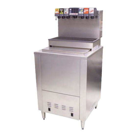
COLD CARB ICE COOLED DISPENSER
SERIES 2308 - DROP IN
Installation and Service Manual
PN 28-0720/05
11/10/09
LANCER
6655 Lancer Blvd.
San Antonio, Texas 78219
To order parts, call
Customer Service: 800-729-1500
Warranty/Technical Support: 800-729-1550
Email: custserv@lancercorp.com
ISO 9001:2000 Quality System Certified
www.lancercorp.com
"Lancer" is the registered trademark of Lancer © 2009 by Lancer, all rights reserved.
Advertisement
Table of Contents

Subscribe to Our Youtube Channel
Related Manuals for lancer 2308 Series


Summary of Contents for lancer 2308 Series
- Page 1 LANCER 6655 Lancer Blvd. San Antonio, Texas 78219 To order parts, call Customer Service: 800-729-1500 Warranty/Technical Support: 800-729-1550 Email: custserv@lancercorp.com ISO 9001:2000 Quality System Certified www.lancercorp.com “Lancer” is the registered trademark of Lancer © 2009 by Lancer, all rights reserved.
-
Page 2: Table Of Contents
TABLE OF CONTENTS SPECIFICATIONS..............................3 1. INSTALLATION OF LANCER ICE COOLED DISPENSER................3 RECEIVING............................3 UNPACKING ............................3 SELECTING A COUNTER LOCATION ....................3 WATER SUPPLY ..........................3 ELECTRICAL SUPPLY ........................4 INSTALLATION OF THE DISPENSER AND PUMP DECK ...............4 CONNECTION OF THE EQUIPMENT ....................5 START UP ............................5 ADJUSTING WATER FLOW ......................6... -
Page 3: Specifications
(45.46 kg) Pouring coffee, tea, and like substances into the drain can cause clogging. WARNING! 1. INSTALLATION OF LANCER ICE COOLED DISPENSER RECEIVING Each unit is tested under operating conditions and inspected before shipment. At the time of shipment, the carrier accepts responsibility for the unit. Upon receiving the unit, carefully inspect the carton for visible damage. -
Page 4: Electrical Supply
Use a filter in the water line to avoid damage to the dispenser. WARNING! C. The carbonator pump is equipped with a strainer on the inlet side. A water supply containing any appreciable quantity of silt, fine sand, or other debris requires a filter ahead of the pump deck. Clean the filter cartridge periodically, depending on the condition of the water. -
Page 5: Connection Of The Equipment
C. After the counter cutout is made, lower the dispenser into the counter. NOTE: In order to ensure unit drainage and proper carbonation, it is necessary for the dispenser to be level, front to back and side to side. D. Position the pump deck under the counter within close proximity to the dispenser. The pump deck must be on a level surface and have adequate electrical utilities available. -
Page 6: Adjusting Water Flow
D. Remove the nozzle by twisting counterclockwise and pulling down. E. Remove the diffuser by pulling down. F. Install Lancer yellow syrup separator (PN 54-0031) in place of the nozzle. G. Activate the dispensing valve to fill the separator syrup tube. -
Page 7: Adjusting Water To Syrup Ratio (Brix)
1.10 ADJUSTING WATER TO SYRUP RATIO (BRIX) A. Hold the brix cup under the syrup separator and activate valve. Check ratio (brix). B. To obtain the proper ratio, use screwdriver to adjust syrup flow control (see Figure 2). C. Remove syrup separator. D. -
Page 8: Mvu Operation
2. MVU OPERATION MVU PLUMBING DIAGRAM - MAKING CONNECTIONS TO THE MVU A. Valves 1-3 and 6-8 are in the normal positions on the tower; however, the MVU is plumbed as shown in the diagram below. Position A is syrup inlet #4 on the cold plate. Position D is syrup inlet #5. -
Page 9: Program Multi Valve Unit (Mvu)
PROGRAM MULTI VALVE UNIT (MVU) Set MVU Buttons as Carbonated, Non-Carbonated, or Flavor Shot Only. The MVU can be programmed to serve soda or plain water beverages as well as a flavor shot from each of the beverage positions on the valve. To enter the programming mode on the MVU and assign water type to each individual brand (Carbonated or Non-carb): A. -
Page 10: Set Mvu For Flavor Shots
E. Press the Pour/Cancel button to lock the changes place exit programming mode. NOTE: The Program will save automatically in 60 seconds if no additional changes are made in that time frame; however, you can exit any time within the 60 second window by pressing Pour/Cancel. - Page 11 D. Press “Shot” again to return to “Drink Type Selection” E. Press the Pour/Cancel Button to lock the changes place exit programming mode. NOTE: The Program will save automatically in 60 seconds if no additional changes are made in that time frame; however, you can exit any time within the 60 second window by pressing Pour/Cancel.
-
Page 12: Flow Rate Check
FLOW RATE CHECK The Dispenser’s water flow rate can be checked/calibrated using the on board computer as a timer. To check/adjust flow rate: A. Remove splashguard and module cover to expose flow controls and solenoids. 1. All active brands should have their shutoffs in the open position as illustrated below. CW = Carbonated Water (sparkling) PW = Plain Water (still) B. -
Page 13: Ratio Process
C. Remove outer nozzle and insert syrup separator. 1. This is important to do during flow rate check so you can determine if the separator has been properly installed. NOTE: Water will leak through to the syrup chamber if not properly installed. D. -
Page 14: Portion Control Programming (Mvu) (No Topoff)
PORTION CONTROL PROGRAMMING (MVU) (NO TOP-OFF) A. Press the S and XL at the same time for five seconds to enter the portion setting mode. 1. The Pour/Cancel light will illuminate and the shot light will blink two times. Press the Brand button. 1. -
Page 15: Portion Control Programming With Top-Off (Mvu)
D. Repeat this step for each of the other size cups. E. Select other brands and repeat these steps for each of them. F. Press the “Pour/Cancel” button to save programming. NOTE: The Program will save automatically in 60 seconds if no additional changes are made in that time frame;... - Page 16 B. Press the brand button. 1. The selected brand’s LED will illuminate. 2. Multiple brands can be programmed at the same time to pour the same amounts for each size during this step. Do this by selecting several brand buttons; however, the first button selected will illuminate and only its beverage will pour.
-
Page 17: Shot Size Programming
SHOT SIZE PROGRAMMING Flavor shot portions can be adjusted using the MVU touchpad and a graduated cylinder. To adjust flavor shots: A. While in Portion Control Programming, press the Shot button. 1. Pressing the Shot button again will exit Shot Size Programming. B. -
Page 18: Dispenser Operation
F. Press Pour/Cancel to save the settings. NOTE: The Program will save automatically in 60 seconds if no additional changes are made in that time frame; however, you can exit any time within the 60 seconds window by pressing Pour/Cancel. The changes you’ve made will be saved. 2.10 DISPENSER OPERATION Crew Serve Beverage Dispensing Flavor Shot Dispensing - Portion Control... -
Page 19: Final Assembly
Beverages - Manual Dispense on Portion Control A. Press the brand button. 1. Button stays active for ten seconds or until another brand is pressed. B. Press and hold the pour/cancel button. 1. The beverage continues to pour until the button is released. -
Page 20: Recommended Services And Maintenance
CLEANING AND SANITIZING SYSTEMS A. General Information (1) Lancer equipment (new or reconditioned) is shipped from the factory cleaned and sanitized according to NSF guidelines. The operator of the equipment must provide continuous maintenance as required by this manual and state and local health department guidelines to maintain proper operation and sanitization. -
Page 21: Cleaning And Sanitizing Bag-In-Box (Bib) Systems
CLEANING AND SANITIZING BAG-IN-BOX (BIB) SYSTEMS A. Disconnect syrup quick disconnect coupling from syrup packages and connect coupling to a bag valve removed from an empty Bag-in-Box package. B. Place end of syrup inlet line, with bag valve attached, in a clean container filled with clean, potable, room-temperature water. -
Page 22: Ice Bin Compartment On All Ice Chests
ICE BIN COMPARTMENT ON ALL ICE CHESTS A. Clean and sanitize the ice bin compartment of the dispenser thoroughly at least once every month. Use the following procedure: B. Prepare cleaning solution and sanitizing solution described in Section 3.2. C. Using the cleaning solution and a clean soft cloth, wash down the sides of the ice bin and the surface of the aluminum casting. -
Page 23: Troubleshooting
4. TROUBLESHOOTING TROUBLE CAUSE REMEDY 4.1 No carbonation. A. Carbonator motor not running. A. Check power supply to see if plugged in. Check if LED light is blinking. If so, reset by unplugging and re-plugging power supply. B. Absence of CO gas. -
Page 24: Led Blinking 4 Blinks Per Second
TROUBLE CAUSE REMEDY 4.4 LED blinking 4 blinks per A. No water to pump. A. Ensure water supply is on, second. carbonator pump motor is connected, and probe is not damaged. Reset by unplugging and re-plugging power supply. 4.5 LED blinking 1 blink per A. - Page 25 NOTES P.N. 28-0720/05...
-
Page 26: Illustrations, Parts Listings And Wiring Diagrams
5. ILLUSTRATIONS, PARTS LISTINGS, AND WIRING DIAGRAMS 5.1 SERIES 2300 DROP-IN P.N. 28-0720/05... - Page 27 5.1 SERIES 2300 DROP-IN - PARTS LIST ITEM PART NO. DESCRIPTION 42-0100 Tank Assy, High Performance 30-9231 Liner, Tank Wrapper, Back 30-10057 Tank Wrapper 51-6225 Rim Assy 30-9267 Lid, Ice Bin 19-0353/02 LEV , 4.5, Portion Control ® 05-2586 Drip Tray 23-0797/02 Cup Rest 30-5424 Splash Plate...
-
Page 28: Remote Pump Assembly
5.2 REMOTE PUMP ASSEMBLY P.N. 28-0720/05... - Page 29 5.2 REMOTE PUMP ASSEMBLY - PARTS LIST ITEM PART NO. DESCRIPTION 01-2700 Adapter, Plastic, 1/2x3/8 Fitting 04-0032/01 Nut, Nylock, 1/4-20 04-0033/01 Washer, Flat, 1/4 x .062 04-0034 Nut, Lock, 1/4-20 04-0236 Screw, 10/21 x .375 04-0247 Isolator, 1/4-20 04-0520/01 Screw, 1/4-20 x .500 06-0075-1 Nameplate, Vinyl 06-3087...
-
Page 30: Tower Assembly, Bevariety Mvu
5.3 TOWER ASSEMBLY, BEVARIETY MVU P.N. 28-0720/05... - Page 31 5.3 TOWER ASSEMBLY, BEVARIETY MVU - PARTS LIST ITEM PART NO. DESCRIPTION 30-10098 Structure, MVU Tower 51-6259 Weldment Assy, Front Cover 17-0622-1 Body Assy, Solenoid, 2-Pack 17-0622-2 Body Assy, Shut-off, 2-Pack 17-0623-1 Body Assy, FC, 3.0, Syrup 17-0623-2 Body Assy, FC, 3.0, SY/WTR 04-0481 Scr, 8-32x1.125, PH, PH/SL, RL 64-5011/02 PCB Assy, Controller, MVU...
-
Page 32: Mvu Assy
5.4 MVU ASSEMBLY ITEM PART NO. DESCRIPTION 05-2748 Adaptor, 1/4 Barb x Dole 02-0005 O-Ring, 2-010, 97-0999 07-0446 Clmp, STPLS, Oetkr, 13/32 07-0433 Clp, STPLS, Oetkr, 1/2 08-0523/01 MVU, Tube, Formed 08-0029 Tubing, Innerbrd, .250ID 54-0481 Nozzle, Hybrid MultiFlavor 05-2766 Lock, Hose, HMFN 01-1280/01 Tee, SS, 1/4 Barb 10 08-0526/01 Tube, Formed, MVU, Inj, 4, 3... -
Page 33: Ice Cooled Universal Wiring Diagram With Bin Lid Switch
5.6 ICE COOLED UNIVERSAL WIRING DIAGRAM WITH BIN LID SWITCH P.N. 28-0720/05... -
Page 34: Ice Cooled Universal Wiring Diagram With Bin Lid Switch And Mvu
5.7 ICE COOLED UNIVERSAL WIRING DIAGRAM WITH BIN LID SWITCH AND MVU P.N. 28-0720/05... -
Page 35: Accessories
5.8 ACCESSORIES Illuminated Merchandiser Illuminated Marquee PN 85-2304 PN 85-2302-20 Splash Guards Kit Water Spigot for Ambient PN 82-3899 Temperature Water Kit PN 82-3903 P.N. 28-0720/05... - Page 36 LANCER To order parts, call Customer Service: 800-729-1500 Warranty: 800-729-1550 Email: custserv@lancercorp.com www.lancercorp.com...
Need help?
Do you have a question about the 2308 Series and is the answer not in the manual?
Questions and answers