Table of Contents
Advertisement
Advertisement
Table of Contents

Related Manuals for lancer bridge tower


Summary of Contents for lancer bridge tower
- Page 1 Bridge Tower Operation Manual Lancer Corporation Technical Support/Warranty 6655 Lancer Blvd. 800-729-1550 San Antonio, Texas 78219 custserv@lancercorp.com 800-729-1500 lancercorp.com PN: 28-0941/01 “Lancer” is the registered trademark of Lancer © 2015 by Lancer, all rights reserved.
-
Page 2: Table Of Contents
TABLE OF CONTENTS ABOUT THIS MANUAL BEFORE GETTING STARTED This booklet is an integral and essential part of the product and Each unit is tested under operating conditions and is thoroughly should be handed over to the operator after the installation and inspected before shipment. -
Page 3: Important Safety Instructions
IMPORTANT SAFETY INSTRUCTIONS ! Intended Use F Power • The dispenser is for indoor use only • Follow all local electrical codes when making connections. • This appliance is intended to be used in commercial applications such as restaurants or similar. •... -
Page 4: Specifications And Features
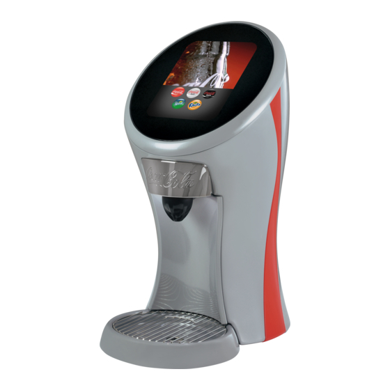
SPECIFICATIONS AND FEATURES 610 mm A. Touch Screen B. Nozzle C. Splash Plate D. Cup Rest E. Drip Tray F. Front Panel 439 mm 325 mm DIMENSIONS PLAIN WATER SUPPLY Width: 325 mm (12.8 inches) Min Flowing Pressure: 20 PSIG (0.137 MPA) Depth: 439 mm (17.3 inches) Max Static Pressure: 50 PSI (0.345 MPA) Height: 610 mm (24 inches) -
Page 5: General System Overview
General System Overview Syrup Line Line Plain Water Line Drain Line Electrical Carb Water Line Carb Water Return A. Water Source B. CO Source C. High Pressure CO Regulator D. Low Pressure CO2 Regulator Manifold E. Electrical Outlet F. Tower (Dispenser) G. -
Page 6: Read This Manual
Read This Manual This manual was developed by Lancer Corporation as a reference guide for the owner/operator and installer of this dispenser. Please read this manual before installation and operation of this dispenser. Please see pages 22-24 for troubleshooting or service assistance. If the service cannot be corrected please call your Service Agent or Lancer Customer Service. -
Page 7: Dispenser/Chiller Installation
Dispenser/Chiller Installation Carefully lift unit and using a screwdriver, seperate the Place gasket at the bottom of the drain then re-attach drain mounting plate from the tower and drip tray. fitting to drip tray, removed in Step 2. Remove the drain fitting from the drip tray. First, unscrew the lower section then press firmly from the bottom to remove the upper portion of the drain fitting. -
Page 8: Dispenser Setup
NOTE 11. Plug in power cord to power supply then route power supply cord to the designated grounded electrical outlet. Unit is designed to be supported by a remote chiller ! WARNING system or remote ice cooled system. Please see the manufacturer’s specifications and instructions for DO NOT PLUG UNIT INTO GROUNDED ELECTRICAL installation. - Page 9 Press one of the top retaining clips, located on the inside 11. Verify all Bag-in-Box contain syrup and check for leaks. of the front panel, and simaltaneously pull forward on the 12. Open the pressure relief valve located on the remote chiller panel to unhook from the retaining clip.
- Page 10 - Tap Four Corners of Screen 19. A keypad will appear, enter the designated pin number to access the service menu. NOTE Contact Lancer Technical Support for the units’ designated pin number. 20. From the service menu press the maintenance button. A. Purge Tab B.
-
Page 11: Adding New Brand/Flavor Module
Adding New Brand/Flavor Module In order to add a new brand or flavor module, the module Press the Configure button under any of the activated brand must first be activated. or flavor modules to open its Configuration Page. From the Service menu, press the Configuration button. Press the Valve Type tab on the far left side of the screen, then select any of the inactive modules. -
Page 12: Calibration And Maintenance
NOTE 10. Once a brand/flavor has been selected to a corresponding Each brand has a default water type and ratio already module, press the Configuration button to return to the set when they are selected. The water type and ratio Configuration Screen. -
Page 13: Calibrating Brand Syrup Modules
Calibrating Brand Syrup Modules NOTE There are two ways that the syrup modules can be calibrated on this unit. Either by using a timed pour and adjusting each valve with the help of a graduated cylinder, or by using a syrup separator and ratio cup with a target flow rate of 44 ml/sec. Both processes are outlined below: NOTE The refrigeration unit should have been running for at least one (1) hour before attempting to set flow rates on valves. The drink temperature should be no higher than 40°F (4.4°C) when flow rates are set. This is best done after the remote chiller has already made an ice bank. Graduated Cylinder: From the Service menu, press the Maintenance button. - Page 14 (See pages 11-12, Adding New Brand/Flavor Module) A. Syrup Seperator in Place of Nozzle Using a Lancer ratio cup, activate the brand syrup module by pressing and holding the Dispense button. Release the button to deactivate the module and capture a sample. A. Flow Rate/Ratio B.
-
Page 15: Calibrating Flavor Modules
Verify that the syrup level is even with the water level in the Repeat steps 7 and 8 if any more brand syrup flow ratio cup. If the dispensed syrup and water levels are not adjustment that is necessary. level, remove the protective cap from the corresponding 10. -
Page 16: Scheduled Maintenance
Scheduled Maintenance • Keep exterior surfaces of dispenser (include drip tray and cup rest) clean As Needed using a clean, damp cloth. • Remove outer nozzle and rinse well in warm water. DO NOT use soap or detergent. This will cause foaming and off taste in finished product. •... -
Page 17: Water Buttons
Water Buttons In order to access the plain and/or carbonated water Once a water button has been dragged and placed over its’ modules from the Main Menu, press the Configuration designated water module, a button will appear on the Main button from the Service Menu. -
Page 18: Sold-Out Feature
Sold-Out Feature From the Service Menu, press the Sold Out button. From the Service Menu, press the Configuration button. Manually adjust specific brands to read Ready, Out, or Auto To add the Auto Sold Out feature to a specific brand, press and hold one of the Sold Out Sensors and drag them to a NOTE corresponding brand. -
Page 19: Brand/Flavor Import
Create a USB drive with the created .brand file in a folder named “brands” as shown in the image below. Plug the USB into the Bridge Tower port located underneath the head of the tower. Once the Brands button turns green then the updated brands will be available. -
Page 20: Video/Screen Saver Import
Once both the video file and list.txt file are in the “ss” folder on the USB Drive, plug in the drive into the Bridge Tower Once the Screen Saver Images button turns green, cycle port located underneath the head of the tower. -
Page 21: Cleaning And Sanitizing
General Information • Lancer equipment (new or reconditioned) is shipped from the factory cleaned and sanitized in accordance with NSF guidelines. The operator of the equipment must provide continuous maintenance as required by this manual and/or state and local health department guidelines to ensure proper operation and sanitation requirements are maintained. -
Page 22: Cleaning And Sanitizing Product Lines
Cleaning and Sanitizing Product Lines Disconnect product lines from BIB’s or other product supply. Prepare Sanitizing Solution described above. Place product lines, with BIB connectors, in a bucket of Place product lines into sanitizing solution and activate warm water. each valve to fill lines with sanitizer. Let sit for ten (10) minutes. -
Page 23: Troubleshooting
Check connection between dispense controller has been lost controller and touchscreen This icon appears on screen: Connection with touchscreen has been Contact Lancer Customer Service for more lost information Water leakage around nozzle. O-ring is damaged or missing. Replace o-ring. - Page 24 TROUBLE CAUSE REMEDY Water only dispensed; no Water or product shutoff on mounting block Open shutoff fully. product; or product only not fully open. Remove valve from mounting block, open dispensed, no water Improper or inadequate water or product shutoffs slightly and check water and flow.
- Page 25 TROUBLE CAUSE REMEDY BIB pump does not operate Out of CO , CO not turned on, or low CO Replace CO supply, turn on CO when dispensing valve opened. pressure. supply, or adjust CO pressure to 70-80 PSI (0.483-0.552 MPA) Out of syrup.
-
Page 26: Illustrations And Part Listings
ILLUSTRATIONS AND PART LISTINGS Main Unit Assembly Item Part No. Description 05-3244 Dynamic Ribbon, Right 05-3249 Bezel Front 04-1689 Screw, M4 04-1689 Screw, M4 05-3252 Splash Plate 82-4895 Cladding Assy, Back 05-3245 Dynamic Ribbon, Left 23-1674 Cup Rest 04-1689 Screw, M4 05-3373 Snapfit Panel Fastener, Riblok 82-4896... -
Page 27: Plumbing Assembly
Plumbing Assembly Item Part No. Description 01-2991 Coupling, Female, 1/2 PVC 30-12139 Plate, Nozzle, 4-Point 04-1710 Washer, Flat, SS 04-1640 Screw, M3 02-0677 Seal, Washer, Drain 05-1385 Elbow, .5 Dole X .2 Barb 01-2994 Fitting, Drain, 1/2 NPT 54-0473 Outlet Assy, Water 05-3407 Nozzle, Overmold Assy, Low Flow 19-0262... -
Page 28: Electronics Assembly
Electronics Assembly Item Part No. Description 52-3683 LED Strip Assy, Ribbon Light 05-3368 Base, LED Ribbon, Touch Tower 82-4863 Screen Assy, Bridge 64-5061 PCB Assy, Valve Board 04-1640 Screw, M3 64-5104 PCB Assy, Pwer Brd, Tower 04-1640 Screw, M3 52-3661 Drip Tray Dual Light Assy 04-1640 Screw, M3... -
Page 29: Unit Plumbing Diagram
Unit Plumbing Diagram Item Description Syrup Line 1 Syrup Line 2 Syrup Line 3 Syrup Line 4 Syrup Line 5 Syrup Line 6 Syrup Line 7 Syrup Line 8 Syrup Line 9 Syrup Line 10 Plain Water Line Soda Line Recirculation Line... -
Page 30: Unit Wiring Diagram
Unit Wiring Diagram... -
Page 31: Counter Cut-Out
Counter Cut-out 286.18 (11.27) 142.56 (5.61) 17.35 128.14 (0.68) 27.61 (5.04) (1.09) 43.84 (4.73) 69.23 (2.72) 92.69 (3.65) 170.05 (6.69) 234.27 (9.22) 142.56 (5.61) 422.47 (16.63) 111.43 (4.39) 19.35 (0.76) 233.88 (9.21) 96.64 (3.82) 15.56 (0.61) - Page 32 Lancer Corp. 800-729-1500 Technical Support/Warranty: 800-729-1550 custserv@lancercorp.com lancercorp.com...
Need help?
Do you have a question about the bridge tower and is the answer not in the manual?
Questions and answers