Table of Contents
Advertisement
Quick Links
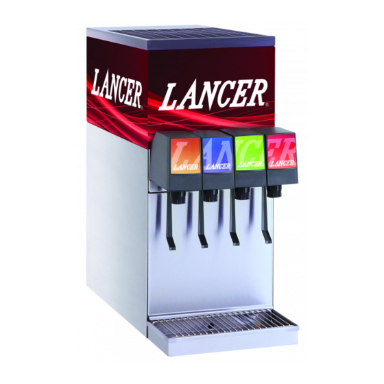
Counter Electric Dispenser
Lancer Series 500
Operation Manual
PN: 28-0063/06
LANCER CORP
6655 Lancer Blvd.
San Antonio, Texas 78219
To order parts, call
Customer Service: 800-729-1500
Warranty/Technical Support: 800-729-1550
Email: custserv@lancercorp.com
ISO 9001:2000 Quality System Certified
www.lancercorp.com
Manual PN: 28-0063/06
"Lancer" is the registered trademark of Lancer © 2013 by Lancer, all rights reserved.
NOVEMBER 10, 2014
FOR QUALIFIED INSTALLER ONLY
Advertisement
Table of Contents

Related Manuals for lancer Series 500


Summary of Contents for lancer Series 500
- Page 1 To order parts, call Customer Service: 800-729-1500 Warranty/Technical Support: 800-729-1550 Email: custserv@lancercorp.com ISO 9001:2000 Quality System Certified www.lancercorp.com Manual PN: 28-0063/06 “Lancer” is the registered trademark of Lancer © 2013 by Lancer, all rights reserved. NOVEMBER 10, 2014 FOR QUALIFIED INSTALLER ONLY...
-
Page 2: Table Of Contents
ABOUT THIS MANUAL This booklet is an integral and essential part of the product and should be handed over to the operator after the instal- lation and preserved for any further consultation that may be necessary. Please read carefully the guidelines and warn- ings contained herein as they are intended to provide the user with essential information for the continued safe use and maintenance of the product. - Page 3 5. DISPENSER DISPOSAL......................19 6. ILLUSTRATIONS, PARTS LISTINGS, AND WIRING DIAGRAMS..........19 INSTALLATION KITS AND OPTIONAL ACCESSORIES............19 CABINET ASSEMBLY....................20-21 COMPRESSOR DECK ASSEMBLY................22-23 500 CED WIRING DIAGRAM, 115V/60HZ, LANCER ELECTRONIC ICE BANK CONTROL...........................24 500 CED WIRING DIAGRAM, 220-240V/50-60HZ, LANCER ELECTRONIC ICE BANK CONTROL...........................25...
-
Page 4: Specifications
TOUCHPOINT SPECIFICATIONS DIMENSIONS WEIGHT CARBONATOR WATER SUPPLY Width: 10 3/8 in (264 mm) Empty: 89 lbs (40.4 kg) Min flowing pressure: 35 PSIG Depth: 25 1/4 in (641 mm) Operating: 125 lbs (55.4 kg) (0.241 BAR) Height (w/out legs): 22 15/16 in Shipping: 108 lbs (49.0 kg) Max static pressure: 60 PSIG (583 mm) -
Page 5: Pre-Intallation Checklist
PRE-INSTALLATION CHECKLIST BEFORE GETTING STARTED Each unit is tested under operating conditions and is thoroughly inspected before shipment. At the time of shipment, the carrier accepts responsibility for the unit. Upon receiv- ing the unit, carefully inspect the carton for visible damage. If damage exists, have the car- rier note the damage on the freight bill and file a claim with carrier. -
Page 6: Warnings/Cautions
WARNING/ADVERTENCIA/AVERTISSEMENT The dispenser is for indoor use only. This appliance is intended for use in commercial applications such as res- taurants, stores or similar. This unit is not a toy. It should not be used by children or infirm persons without supervi- sion. - Page 7 25 PSIG (0.172 MPA). REGLES DE SECURITE POUR L’NSTALLATION DU DISTRIBUTEUR DE SODAS La proprètè da cet ensamable est assurè à I’usine sulvant les spècifications èmis par Lancer . Il est essentiel de respecter les 6 points suivants pour l’installation de l’appareil: 1.
- Page 8 ELECTRICAL WARNING/ADVERTENCIA ELÉCTRICA/ AVERTISSEMENT ÉLECTRIQUE Check the dispenser serial number plate for correct electrical requirements of unit. Do not plug into a wall electrical outlet unless the current shown on the serial number plate agrees with local current available. Follow all local electrical codes when making connections.
- Page 9 AUTOMATIC AGITATION/AGITACIÓN AUTOMÁTICA/ Units are equipped with an automatic agitation system and will activate unexpectedly. Do not place hands or for- eign objects in the water bath tank. Unplug the dispenser during servicing, cleaning, and sanitizing. To avoid personal injury, do not attempt to lift the dispenser without assistance. For heavier dispensers, use a mechanical lift. Las unidades están equipadas con un sistema automático de agitación, por lo que se pueden activar repentina- mente.
-
Page 10: Installation
1. INSTALLATION RECIEVING THE UNIT Each unit is completely tested under operating conditions and thoroughly inspected before ship- ment. At time of shipment, the carrier accepts the unit and any claim for damage(s) must be made with carrier. Upon receiving units from the delivering carrier, carefully inspect carton for visible indication(s) of damage. -
Page 11: Connecting To Electrical Power
A. Using appropriate tubing and fittings, connect tubing assembly to water source. Do not reuse beverage tubing. Installer should provide new beverage tubing that meets the IEC Standard 61770. Do not reuse beverage tubing. Lancer beverage tubing kits are available for purchase. Contact your Sales Representative or Lancer Customer Service for more information. -
Page 12: Connecting To Co
CONNECTING THE CO2 SUPPLY A. Connect high pressure CO2 regulator assembly to CO2 cylinder or bulk system. Use a new CO2 tank washer if regulator does not have built-in o-ring seal. B. Place CO2 cylinder in service location under counter, etc., and secure it with a safety chain. C. -
Page 13: Adjusting Water Flow (Lev®)
1.11 ADJUSTING WATER TO SYRUP (RATIO) BRIX (LEV ® A. Hold the Lancer brix cup under the syrup separator and activate valve. Check brix. B. To obtain the proper brix, use screwdriver to adjust syrup flow control (see Figure 1). -
Page 14: Yearly
3. DISPENSER CLEANING AND SANITIZATION GENERAL INFORMATION A. Lancer equipment (new or reconditioned) is shipped from the factory cleaned and sanitized in accordance with NSF guidelines. The operator of the equipment must provide continuous maintenance as required by this manual and/or state and local health department guidelines to ensure proper operation and sanitation requirements are maintained. -
Page 15: Valves
VALVES A. Valves may be cleaned and sanitized in the same manner B. Remove cover and disconnect power so not to activate the valve while cleaning. Remove nozzle and diffuser. Wash these parts in cleaning solution, then immerse them in a bath of sanitizing solution for 15 minutes. -
Page 16: Troubleshooting
4. TROUBLESHOOTING TROUBLE CAUSE REMEDY 4.1 Water leakage around nozzle. A. Damaged or improperly installed o-ring A. if damaged, replace. If imporoperly above diffuser. installed, adjust. 4.2 Leakae between upper and lower A. Gap between upper and lower valve A. Tighten all six (6) retaining screws. valve bodies. -
Page 17: No Product Dispensed
TROUBLE CAUSE REMEDY 4.7 No product dispensed A. Water and syrup shutoffs on mounting A. Open shutoff fully. block not fully open. B. The key switch on an electric valve is B. Turn key switch to ON position. in the OFF position. C. -
Page 18: Runs
TROUBLE CAUSE REMEDY 4.11 Compressor does not start (no hum), A. Compressor relay or overload A. Replace compressor relay or overload. but condenser fan motor runs malfunctioning. B. Inadequate voltage. B. Measure voltage across common and run terminal on compressor. Voltage must not drop below 90% of rated voltage. -
Page 19: Compressor And Condenser Fan Motor Will Not Start After Five
4.16 Compressor and Condenser Fan A. Transformer tripped. A. Reset transformer. Motor will not start after five (5) minute Power Off Delay (Lancer EIBC Export B. Relay will not turn on compressor B. Failed relay. Replace Control Board. only) C. Probe unplugged C. -
Page 20: Cabinet Assembly
CABINET ASSEMBLY... - Page 21 CABINET ASSEMBLY (CONTINUED) Item Part No. Description Item Part No. Description 30-5260/01 Wrapper, Cabinet CAGE ASSY Part Numbers 07-0347 Plate, Cover 23-0796/01 2 Valve, Cold, Split 23-1111 Cup Rest 23-0905 2 Valve, Hot, Split 51-0735 Drip Tray Assy 23-1224/02 3 Valve, Cold, Flooded 30-5037 Frame, Drip Tray 23-1225/02...
-
Page 22: Compressor Deck Assembly
COMPRESSOR DECK ASSEMBLY... - Page 23 COMPRESSOR DECK ASSEMBLY (CONTINUED) Item Part No. Description Item Part No. Description 82-2662 Compressor Deck Assy, 52-1258 Fan Motor Assy, 115V/60Hz, 9W 115V/60Hz 52-0915 Fan Motor Assy, 220V/50-60Hz, 82-2665 Compressor Deck Assy, 230V/50Hz 29A 91-0007 Fan Motor, 115V/60Hz, 9W 82-2666 Compressor Deck Assy, 91-0035 Fan Motor, 220V/50-60Hz, 5W...
-
Page 24: 500 Ced Wiring Diagram, 115V/60Hz, Lancer Electronic Ice Bank Control
500 CED WIRING DIAGRAM, 115V/60HZ, LANCER ELECTRONIC ICE BANK CONTROL IMPORTANT WHEN STARTING UNIT OR IF CURRENT IS INTERRUPTED, THERE IS A FIVE (5) MINUTE DELAY BEFORE THE COMPRESSOR/FAN STARTS. OVERLOAD GREEN JCT. BLACK MOTOR WHITE COMPRESSOR AGITATOR MOTOR RELAY... -
Page 25: 500 Ced Wiring Diagram, 220-240V/50-60Hz, Lancer Electronic Ice Bank Control
500 CED WIRING DIAGRAM, 220-240V/50-60HZ, LANCER ELECTRONIC ICE BANK CONTROL IMPORTANT WHEN STARTING UNIT OR IF CURRENT IS INTERRUPTED, THERE IS A FIVE (5) MINUTE DELAY BEFORE THE COMPRESSOR/FAN STARTS. OVERLOAD GREEN BLACK MOTOR WHITE COMPRESSOR AGITATOR MOTOR RELAY 24V LEADS... - Page 26 LANCER To order parts, call Customer Service: 800-729-1500 Warranty: 800-729-1550 Email: custserv@lancercorp.com www.lancercorp.com...
Need help?
Do you have a question about the Series 500 and is the answer not in the manual?
Questions and answers