Table of Contents
Advertisement
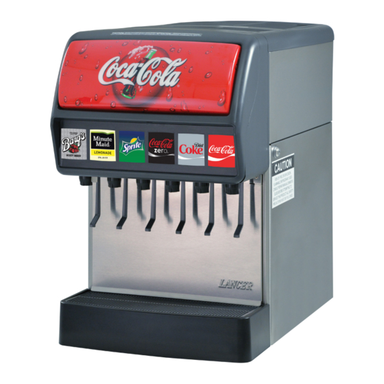
Delta-600 R-290
Counter Electric Dispenser
Operation Manual
Lancer Corporation
Tech Support/Warranty: 800-729-1550
6655 Lancer Blvd.
email: custserv@lancercorp.com
®
San Antonio, Texas 78219
web: lancercorp.com
9000
800-729-1500
Lancer PN: 28-1002/01-01
Revision: 01-1 - February 2019
"Lancer" is the registered trademark of Lancer © 2019 by Lancer, all rights reserved.
Advertisement
Table of Contents

Related Manuals for lancer Delta-600 R-290


Summary of Contents for lancer Delta-600 R-290
- Page 1 Lancer Corporation Tech Support/Warranty: 800-729-1550 6655 Lancer Blvd. email: custserv@lancercorp.com ® San Antonio, Texas 78219 web: lancercorp.com 9000 800-729-1500 Lancer PN: 28-1002/01-01 Revision: 01-1 - February 2019 “Lancer” is the registered trademark of Lancer © 2019 by Lancer, all rights reserved.
-
Page 2: Table Of Contents
TABLE OF CONTENTS ABOUT THIS MANUAL BEFORE GETTING STARTED This booklet is an integral and essential part of the product. Each unit is tested under operating conditions and is thoroughly Please carefully read the guidelines and warnings contained inspected before shipment. At the time of shipment, the carrier herein as they are intended to provide the user with essential accepts responsibility for the unit. -
Page 3: Important Safety Instructions
DO NOT ‘gang’ together with other electrical devices on the • Replace component parts with like components. Only use same outlet. genuine Lancer parts or parts certified by Lancer. • DO NOT locate multiple portable socket-outlets or portable power •... -
Page 4: Pre-Installation
PRE-INSTALLATION Specifications & Features 26.86 in. 25.56 in. A. Bonnet 16.86 in. B. Key Lock Switch C. Merchandiser D. Splash Plate E. Cup Rest F. Drip Tray DIMENSIONS PLAIN WATER SUPPLY Width: 16.86 inches (429 mm) Min Inlet Pressure: 25 psi (0.172 MPa) Depth: 25.56 inches (649 mm) Max Static Pressure: 65 psi (0.448 MPa) Height: 26.86 inches (657 mm) -
Page 5: General System Overview
Conditioning Ducts Drill Oetiker Clamp Fittings Do you have enough space to install the dispenser? BIB SYSTEM: Water Booster (Lancer PN: 82-3401 or MC-163172 Does the counter height meet BIB Rack ADA requirements? Water Regulator (supplied with BIB Syrup Boxes... -
Page 6: Installation
Please read this manual before installation and operation of this dispenser. Please see pages 14 - 16 for troubleshooting or service assistance. If the service cannot be corrected please call your Service Agent or Lancer Customer Service. Always have your model and serial number available when you call. -
Page 7: Dispenser Installation
The dispenser is designed to be installed either permanently to counter or placed on a counter using the legs (included in the Lancer kit, PN 82-1704). NOTE A. Bucket NSF listed units must be sealed to the counter or use B. - Page 8 H WARNING Never energize the machine if there is any trace of damage. Contact Lancer Customer Service for assistance. ! WARNING A. Carbonator B. Carb Water Inlet The dispenser must be properly electrically grounded to avoid serious injury or fatal electrical shock. The...
-
Page 9: Installing Co Supply
Installing CO Supply Connect high pressure CO regulator assembly to CO Connect tubing routed from the syrup pump location to the cylinder or bulk system. second outlet of the low pressure CO regulator manifold. ! ATTENTION Before installing regulator, assure that a seal (washer or o-ring) is present in regulator attachment nut. -
Page 10: Dispenser Setup
10. Activate each valve until a steady flow of carbonated water is achieved. Adjust Water Flow Rate & Syrup/Water Ratio - LEV NOTE Using a Lancer brix cup verify water flow rate (5 oz. in 4 sec.). Use a screwdriver to adjust if needed. Do not set flow rates or dispense from the unit until after a complete ice bank is established. -
Page 11: Volumetric Valve Adjustment
Activate valve to purge syrup until steady flow is achieved. down, then remove diffuser by pulling down. Using a Lancer brix cup, activate the valve and capture a Install Lancer (yellow) syrup separator (PN 54-0031) in place sample. Verify that the syrup level is even with the water of nozzle. -
Page 12: Cleaning And Sanitizing
General Information • Lancer equipment (new or reconditioned) is shipped from the factory cleaned and sanitized in accordance with NSF guidelines. The operator of the equipment must provide continuous maintenance as required by this manual and/or state and local health department guidelines to ensure proper operation and sanitation requirements are maintained. -
Page 13: Cleaning And Sanitizing Nozzles
• Unplug the dispenser from the power source. Monthly • Remove the bonnet and clean the dirt from the gas cooler using a soft brush. • Replace the bonnet and plug in the unit. • Clean and sanitize the unit using the appropriate procedures outlined in the Cleaning and Every Six Months Sanitizing section of this manual. -
Page 14: Troubleshooting
TROUBLESHOOTING Dispenser Troubleshooting TROUBLE CAUSE REMEDY Water leakage around nozzle. O-ring not properly installed above diffuser Install or replace o-ring correctly. O-ring is damaged or missing. Replace o-ring. Leakage between upper and Gap between upper and lower valve Tighten all six (6) retaining screws. lower bodies. - Page 15 TROUBLE CAUSE REMEDY Water only dispensed; no syrup; Water or syrup shutoff on mounting block Open shutoff fully. or syrup only dispensed, no water not fully open. Remove valve from mounting block, open Improper or inadequate water or syrup shutoffs slightly and check water and flow.
- Page 16 Post-Mix Troubleshooting TROUBLE CAUSE REMEDY BIB pump does not operate when Out of CO , CO not turned on, or low CO Replace CO supply, turn on CO dispensing valve opened. pressure. supply, or adjust CO pressure to 70-80 Psi (0.483-0.552 MPa) Out of syrup.
-
Page 17: The Electronic Ice Bank Control
THE ELECTRONIC ICE BANK CONTROL (EIBC) Checking the Normal PCB Operation ! WARNING Terminal block has ac line voltage and, when servicing the unit, should be covered with tape. Tape should cover bare electrical connections to prevent electrical shock. Turn power OFF or insure that power has been disconnected from dispenser 24 VAC Disconnect leads from the terminal block that connect to the PCB, noting their specific location for re-connection. Ice Bank Probe Disconnect both the Ice Bank probe (J6) and the Carbonator probe (J3) (if equipped) connections from board. -
Page 18: Illustrations And Part Listings
ILLUSTRATIONS AND PART LISTINGS Main Unit Assembly Item Part No. Description 54-0292 Merchandiser Assembly 05-3711 Drip Tray 30-7619 Bonnet Face 05-1585 Cup Rest 23-1255 Bonnet Assembly 19-0359 LEV, Self-Service Lever 12-0097 Key-switch Assembly 05-1110 Upper Body, GMV 51-6711 Wrapper Assembly 82-0274 Back-block 30-13199... -
Page 19: Refrigeration Deck Assembly - R290
Refrigeration Deck Assembly - R290 Item Part No. Description 82-5211 Refrigeration Deck Assy (115H) 83-0082 Compressor Assembly (115V) 82-5227 Refrigeration Deck Assy (230V) 83-0083 Compressor Assembly (230V) 52-1773 EIBC Probe Assembly 82-5215 Agitator Assembly (115V) 30-5866 Fan Shroud Bottom 82-5216 Agitator Assembly (230V) 30-5865 Fan Shroud Top... -
Page 20: Carbonator, Water/Syrup Line Assembly
Carbonated, Water/Syrup Line Assemblies Item Part No. Description 23-1514 Water/Soda Cage Assembly 48-0478 Tubing Assembly, Syrup #6/5/4, 6/5/4V 01-0252 Connector 54-0066 Relief Valve Assembly 48-0473 Tubing Assembly, Syrup #1 17-0469 Check Valve Assembly 48-0474 Tubing Assembly, Syrup #2, 6V 52-0909 Carbonator Probe 48-0475 Tubing Assembly, Syrup #3... -
Page 21: Carbonator Deck/Pump Bracket Assembly
Carbonator Deck/Pump Bracket Assemblies Item Part No. Description 91-0063 Carbonator Motor (115V) 91-0065 Carbonator Motor (230V) 07-0017 Clamp with Screw 86-0084 Carb Pump 30-6800 Deck Plate... -
Page 22: Control Housing Assembly
Control Housing Assembly Item Part No. Description 64-5132/02 PCB Assy, R290, Refr., Control 06-3584 Wire Diagram Label, 115/60 HZ, 230/50 HZ, 220/60 Hz, Delta 06, 05-1678 Standoff, PCB, Rev Locking R290 12-0660 Rocker Switch, Sealed, 04-0072 Rivet, 0.125 Dia X 0.312, SS 250 VAC, 16A 06-4011 ON/OFF Label, R290 Electrical... -
Page 23: Wiring Diagram
Wiring Diagram... -
Page 24: Plumbing Diagram
Plumbing Diagram PRESSURE SETTINGS 75 psi WATER 50 psi PLAIN WATER COILS CARB. HIGH PRESSURE WATER PUMP ® PLUMBING DIAGRAM DELTA III 9000 PLAIN WATER INLET TO CARBONATOR Lancer Corp. 800-729-1500 Technical Support/Warranty: 800-729-1550 custserv@lancercorp.com lancercorp.com...
Need help?
Do you have a question about the Delta-600 R-290 and is the answer not in the manual?
Questions and answers