lancer 2200 Series Manual
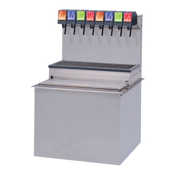
Ice cooled drop-in
Hide thumbs
Also See for 2200 Series:
- Operation manual (42 pages) ,
- Installation manual (13 pages) ,
- Operation manual (28 pages)
Table of Contents
Advertisement
Quick Links
FOR QUALIFIED INSTALLER ONLY. This basic installation sheet is an initial release. If a complete operations
manual (for the unit being installed) is required or needed, please refer to the Lancer web site (lancerworldwide.
com) for immediate access, or for your convenience, scan this QR code with a mobile device (app required) for
immediate access to other Technical Documents and alternative translations (if available) pertaining to this unit.
Contact Lancer Customer Service for assistance as required.
ABOUT THIS GUIDE
This guide is an integral and essential part of the product and
should be handed over to the operator after the installation to
keep as a reference. Please read carefully the guidelines and
warnings contained herein as they are intended to provide the
user with essential information for the continued safe use and
maintenance of the product. In addition, it provides GUIDANCE
ONLY to the user on the correct services and site location of the
unit.
The installation or relocation of this product must be carried out by qualified personnel with up-to-date safety
and hygiene knowledge and practical experience, in accordance with current regulations.
IMPORTANT SAFETY INSTRUCTIONS
! Intended Use
The dispenser is for indoor use only. This unit is not a toy. Children should be supervised not to play with appliance. It should not
be used by children or infirm persons without supervision. This appliance can be used by children aged from 8 years and above
and persons with reduced physical, sensory or mental capabilities or lack of experience and knowledge if they have been given
supervision or instruction concerning use of the appliance in a safe way and understand the hazards involved. Cleaning and
user maintenance shall not be performed by children without supervision. The min/max ambient operating temperature for the
dispenser is 40°F to 105°F (4°C to 41°C) at a max altitude of 16,400 ft (5,000 m). Do not operate unit outside these conditions.
Should freezing occur, cease operation of the unit and contact authorized service technician. Service, cleaning, and sanitizing
should be accomplished only by trained personnel. During installation, old hose sets should not be reused to connect the unit to
the water mains; new hose sets should always be used. Applicable safety precautions must be observed. Instruction warnings on
the product being used must be followed.
F Electrical Warning
Check the dispenser nameplate label, located behind the splash plate, for the correct electrical requirements of unit.
into a wall electrical outlet unless the current shown on the serial number plate agrees with local current available. Follow all local
electrical codes when making connections. Each dispenser must have a separate electrical circuit. Do not use extension cords
with this unit. Do not 'gang' together with other electrical devices on the same outlet.
lets or portable power supplies at the rear of the appliance.
primary. Always disconnect electrical power to the unit to prevent personal injury before attempting any internal maintenance. The
resettable breaker switch should not be used as a substitute for unplugging the dispenser from the power source to service the
unit. Only qualified personnel should service internal components of electrical control housing. Make sure that all water lines are
tight and units are dry before making any electrical connections!
Lancer
is a registered trademark of Lancer Corp.
®
For more Information visit
6655 Lancer Boulevard • San Antonio, TX 78219 • custserv@lancerworldwide.com • ©2022 Lancer Corp. • Lancer PN: 28-0484 • Revision 05-1, 09/14/22
BEFORE GETTING STARTED
Each unit is tested under operating conditions and is thoroughly
inspected before shipment. At the time of shipment, the carri-
er accepts responsibility for the unit. Upon receiving the unit,
carefully inspect the carton for visible damage. If damage exists,
have the carrier note the damage on the freight bill and file a
claim with carrier. Responsibility for damage to the dispenser lies
with the carrier.
The key-switch does not disable the line voltage to the transformer
lancerworldwide.com
Ice Cooled Drop-In
Series: 2200, 2300, 23300
Do not locate multiple portable socket-out-
or call Tech Support/Warranty: 800-729-1550
Do not plug
Advertisement
Table of Contents

Related Manuals for lancer 2200 Series


Summary of Contents for lancer 2200 Series
- Page 1 Lancer Corp. ® For more Information visit lancerworldwide.com or call Tech Support/Warranty: 800-729-1550 6655 Lancer Boulevard • San Antonio, TX 78219 • custserv@lancerworldwide.com • ©2022 Lancer Corp. • Lancer PN: 28-0484 • Revision 05-1, 09/14/22...
-
Page 2: Specifications
5 Carbon Dioxide (CO ) Warning • Carbon Dioxide (CO ) is a colorless, noncombustible gas with a light pungent odor. High percentages of CO may displace oxygen in the blood. • Prolonged exposure to CO can be harmful. Personnel exposed to high concentrations of CO gas will experience tremors which are followed by a loss of consciousness and suffocation. - Page 3 ICDI 2300 Standard Performance DIMENSIONS WEIGHT PLAIN WATER SUPPLY Width: 25.2 inches (640 mm) Shipping: 215 lbs (98 kg) Min Flowing Pressure: 40 psi (0.276 MPa) Depth: 25.2 inches (640 mm) Operating (with Ice): 258 lbs (117 kg) Max Flowing Pressure: 80 psi (0.552 MPa) Height: 42.4 inches (1077 mm) Ice Capacity: 100 lbs (45 kg) CARBON DIOXIDE (CO...
-
Page 4: Unpacking The Dispenser
Read This Guide This guide was developed by Lancer Worldwide as a reference for the owner/operator and installer of this dispenser. Please read this guide before installation and operation of this dispenser. Please see Troubleshooting section for service assistance. If the service cannot be corrected please call your Service Agent or Lancer Customer Service. - Page 5 The unit can extend up to 23 inches (58.42 cm) below the counter, including the shipping risers, which Lancer recommends be left attached to the unit. Should the dispenser ever require removal, the shipping risers will protect the inlet tubes from being damaged.
- Page 6 13. Attach BIB connectors on syrup supply line to BIB. Repeat 16. Install drain lines to both front and back drain fittings. for each syrup line/pump. ! ATTENTION Use proper connector for syrup manufacturer. A. Syrup Supply Line 17. Route drain hoses to designated open type drain. B.
- Page 7 Install water regulator and filter to water line and, if riser legs in the back of the unit. necessary, install water booster (Lancer PN MC-163172) between water supply and the unit. Using tubing cutters, cut soda water line and install remote carbonator per manufacturer’s specifications.
- Page 8 11. Connect each syrup line to appropriate syrup inlet in the 15. Install threaded drain fitting (PN: 01-1612), included in front of the unit (see Plumbing Diagrams on the front of the accessory kit, to front drain line. unit or on pages 17-20 for reference). ! ATTENTION If installing a 6-Valve unit, two of the syrup lines will be capped.
- Page 9 Installing CO Supply Connect high pressure CO regulator assembly to CO Turn the knob on the CO regulator, at the source, all the cylinder or bulk system. way to the left (counterclockwise) to close the regulator. Repeat for CO regulator at the syrup pumps. ! ATTENTION Before installing regulator, ensure that a seal (washer A.
-
Page 10: Dispenser Setup
Dispenser Setup Turn on water source. Turn on CO at the source then turn the knob on the CO regulator at source to the right (clockwise) until regulator Place enough ice in the ice bin to fill approximately 1/2 of reads 105 psi (0.724 MPa). - Page 11 11. Remove the Valve ID Panel for the first valve. 12. Use a Lancer ratio cup to verify water flow rate (5 oz. in 4 sec.). Use a screwdriver to adjust if needed. Increase Decrease A. Flow Control, Water A. Valve ID Panel B.
-
Page 12: Cleaning And Sanitizing
General Information GENERAL INFORMATION Lancer equipment is shipped from the factory after being cleaned and sanitized in accordance with the National Sani- tation Foundation (NSF) guidelines. The operator of the equipment must provide continuous maintenance as required by this manual and/or state and local health department guidelines to ensure proper operation and sanitation require- ments are maintained. -
Page 13: Cleaning And Sanitizing Nozzles
Cleaning and Sanitizing Nozzles Prepare the cleaning and sanitizing solutions as described in Remove diffuser by pulling down. “Cleaning and Sanitizing Solutions” section. Rinse nozzle and diffuser with warm water. Disconnect power, so as to not activate valve while clean- Wash nozzle and diffuser with cleaning solution then ing. -
Page 14: Dispenser Troubleshooting
TROUBLESHOOTING Dispenser Troubleshooting TROUBLE CAUSE REMEDY No product when valve Keyswitch is off or keyswitch harness is Turn keyswitch on and/or reconnect keyswitch is activated. disconnected. harness. No power to dispenser. Check internal breaker and incoming power. Malfunctioning switch assembly. Replace switch assembly. - Page 15 TROUBLE CAUSE REMEDY Low or no carbonation. Low or no CO Check CO supply. Adjust CO pressure to 90 PSI - 110 PSI (0.621 MPA - 0.758 MPA). Low water pressure. Need water booster kit. Worn or defective carbonator pump. Replace carbonator pump.
-
Page 16: Dispenser Disposal
TROUBLE CAUSE REMEDY Water in ice bin. Cold plate drain is obstructed. Remove obstruction from drain wire. Noisy/cavitating carbon- Insufficient incoming water supply pressure. Verify incoming supply water pressure to ator pump. carbonator pump is 40 PSI (0.276 MPA) and Loose pump coupling. -
Page 17: Plumbing Diagrams
Plumbing Diagrams 2200, Standard Performance, 5 Valve & 6 Valve, (3-1-2) & (2-1-2) 2200, Standard Performance, 6 Valve, (3-2-1) - Page 18 2300, 6 Valve, Standard Performance 2300, 8 Valve, Standard Performance 2300, 10 Valve, Standard Performance...
- Page 19 2300, 6 Valve, High Performance Plumbing Diagram 2300, 8 Valve, High Performance Plumbing Diagram 2300, 10 Valve, High Performance Plumbing Diagram...
- Page 20 Tower Plumbing Diagrams 2300, Standard Performance 6 Valve 2300, Standard Performance 8 Valve 2300, Standard Performance 10 Valve...
-
Page 21: Wiring Diagrams
Wiring Diagrams ICE COOLED UNIVERSAL Ice Cooled Universal Wiring Diagram with Bin Lid Switch WIRING DIAGRAM WITH BIN LID SWITCH WATER SPIGOT BUTTON SYRUP OUT LIGHT KIT REPLACES INTERNAL CHERRY SWITCH HARNESS PRESSURE SWITCH ON SPRITE VALVE SOLENOID BLACK BLACK WHITE BLACK WHITE... -
Page 22: Counter Cutout Diagrams
Counter Cutout Diagrams 2200 Cutout 23 1/4" (591 mm) 17" 15 1/4" FRONT (432 mm) (387 mm) 25" (635 mm) SIDE (View Looking Down) 2323 Cutout 23 1/4" (591 mm) 25.5" 23 1/4" (648 mm) (591 mm) 25.25" (641 mm) 3023 Cutout 30 1/4"...
Need help?
Do you have a question about the 2200 Series and is the answer not in the manual?
Questions and answers