lancer 2200 Series Operation Manual
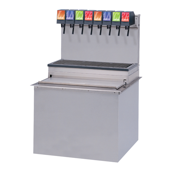
Ice cooled dispener
Hide thumbs
Also See for 2200 Series:
- Operation manual (42 pages) ,
- Manual (23 pages) ,
- Installation manual (13 pages)
Table of Contents
Advertisement
Quick Links
Ice Cooled Dispener 1523 Series 2200
Operation Manual
PN: 28-0086/03
Lancer Corp.
6655 Lancer Blvd.
San Antonio, Texas 78219
800-729-1500
Technical Support/Warranty: 800-729-1550
custserv@lancercorp.com
lancercorp.com
Manual PN: 28-0086/03
11/03/97
MODEL NO.
FOR QUALIFIED INSTALLER ONLY
"Lancer" is the registered trademark of Lancer © 2014 by Lancer, all rights reserved.
Advertisement
Table of Contents

Related Manuals for lancer 2200 Series


Summary of Contents for lancer 2200 Series
- Page 1 PN: 28-0086/03 Lancer Corp. 6655 Lancer Blvd. San Antonio, Texas 78219 800-729-1500 Technical Support/Warranty: 800-729-1550 custserv@lancercorp.com lancercorp.com Manual PN: 28-0086/03 11/03/97 MODEL NO. FOR QUALIFIED INSTALLER ONLY “Lancer” is the registered trademark of Lancer © 2014 by Lancer, all rights reserved.
-
Page 2: Table Of Contents
The installation and relocation, if necessary, of this product must be carried out by qualified personnel with up-to-date safety and hygiene knowledge and practical experience, in accordance with current regulations. TABLE OF CONTENTS SPECIFICATIONS..........................3 PRE-INTALLATION CHECKLIST......................4 WARNINGS/CAUTIONS........................5-8 1. INSTALLATION OF LANCER ICE COOLED DISPENSER............9 UNPACKING.........................9 SELECT A COUNTER LOCATION..................9 WATER SUPPLY........................9 ELECTRICAL SUPPLY......................10 SYRUP CONTAINERS.......................10 INSTALLATION OF THE UNIT....................10... -
Page 3: Specifications
ICD 1523 SPECIFICATIONS DIMENSIONS WEIGHT PLAIN WATER SUPPLY Width: 15 inches (381 mm) Operating: 166 lbs (75 kg) Min flowing pressure: Depth: 23 inches (584 mm) Shipping: 130 lbs (59 kg) 20 PSI (0.138 MPA) Height: 33.375 inches (848 mm) Max flowing pressure: 50 PSI (0.345 MPA) COUNTER CUT-OUT... -
Page 4: Pre-Intallation Checklist
PRE-INSTALLATION CHECKLIST BEFORE GETTING STARTED Each unit is tested under operating conditions and is thoroughly inspected before shipment. At the time of shipment, the carrier accepts responsibility for the unit. Upon receiv- ing the unit, carefully inspect the carton for visible damage. If damage exists, have the car- rier note the damage on the freight bill and file a claim with carrier. -
Page 5: Warnings/Cautions
WARNING/ADVERTENCIA/AVERTISSEMENT The dispenser is for indoor use only. This unit is not a toy. Children should not be supervised not to play with appliance. It should not be used by children or infirm persons without supervision. This appliance is not intended for use by persons (including children) with reduced physical, sensory or mental capabilities, or lack of experience and knowledge, unless they have been given supervision or instruction concerning use of the appliance by a person responsible for their safety. - Page 6 20 PSIG (0.138 MPA). REGLES DE SECURITE POUR L’NSTALLATION DU DISTRIBUTEUR DE SODAS La proprètè da cet ensamable est assurè à I’usine sulvant les spècifications èmis par Lancer . Il est essentiel de respecter les 6 points suivants pour l’installation de l’appareil: 1.
- Page 7 ELECTRICAL WARNING/ADVERTENCIA ELÉCTRICA/ AVERTISSEMENT ÉLECTRIQUE Check the dispenser serial number plate for correct electrical requirements of unit. Do not plug into a wall electrical outlet unless the current shown on the serial number plate agrees with local current available. Follow all local electrical codes when making connections.
- Page 8 AUTOMATIC AGITATION/AGITACIÓN AUTOMÁTICA/ Units are equipped with an automatic agitation system and will activate unexpectedly. Do not place hands or for- eign objects in the water bath tank. Unplug the dispenser during servicing, cleaning, and sanitizing. To avoid personal injury, do not attempt to lift the dispenser without assistance. For heavier dispensers, use a mechanical lift. Las unidades están equipadas con un sistema automático de agitación, por lo que se pueden activar repentina- mente.
-
Page 9: Installation Of Lancer Ice Cooled Dispenser
1. INSTALLATION OF LANCER ICE COOLED DISPENSER UNPACKING A. The Lancer Ice Cooled Dispenser is shipped in a corrugated shipping carton. B. Carefully remove the corrugated shipping carton from the unit. C. Remove parts from the Ice Compartment. D. Inspect unit for concealed damage(s). If evident, notify delivering carrier and file a claim against same. -
Page 10: Electrical Supply
NOTE: Remember that the unit can extend up to 23 inches (58.42 cm) below the counter, including the shipping risers, which Lancer recommends be left attached to the unit. Should the dispenser ever require removal, the shipping risers will protect the inlet tubes from being damaged. -
Page 11: Connection Of The Unit
CONNECTION OF THE UNIT A. Position the CO2 gas tank in the desired location. Assemble the high pressure regulator to the CO2 gas tank and run jumper line to low pressure regulator. B. Attach the CO2 gas line to the carbonator by attaching the line from the high pressure regulator to the single check valve marked “gas”... -
Page 12: Adjusting Water Flow
G. Activate dispensing valve to fill the separator syrup tube. H. Hold a Lancer BRIX cup (PN 05-0090) under the syrup separator and dispense water and syrup into the BRIX cup for four (4) seconds. Divide the number of ounces (ml) of water in the cup by four (4) to determine the water flow rate per second. -
Page 13: Replenishing Syrup Supply (5 Gallon Tanks)
CLEANING AND SANITIZING SYSTEMS A. General Information 1. Lancer equipment (new or reconditioned) is shipped from the factory cleaned and sanitized in accordance with NSF guidelines. The operator of the equipment must provide continuous maintenance as required by this manual and/or state and local health department guidelines to ensure proper operation and sanitation requirements are maintained. -
Page 14: Cleaning And Sanitizing Figal Systems
4. Recommended Preparation of Sanitizing Solutions. a. Sanitizing solutions should be prepared in accordance with the manufacturer’s written recommendations and safety guidelines. For example, mix Diversol CX in clean, potable water at a temperature of 90 to 110 degrees Fahrenheit so that the solution provides 200 parts per million (PPM) available chlorine. -
Page 15: Celaning And Sanitizing Bag-In-Box (Bib) Systems
N. Fill a tank with sanitizing solution. Connect syrup line to the tank. Connect CO2 supply hose to tank and pressurize. O. Remove dispensing valve nozzle (twist and pull down) and pull out center mixing baffle. Using a plastic bristle brush and detergent soap solution scrub the nozzle, mixing baffle, bottom of dispensing valve, and cup lever. -
Page 16: Valves
CAUTION FOLLOWING SANITIZATION, RINSE WITH END-USE PRODUCT UNTIL THERE IS NO AFTERTASTE. DO NOT USE A FRESH WATER RINSE. THIS IS A NSF REQUIREMENT. RESIDUAL SANITIZING SOLUTION LEFT IN THE SYSTEM CREATES A HEALTH HAZARD. PRECAUCIÓN DESPUÉS DE LA ESTERILIZACIÓN, ENJUAGUE CON EL PRODUCTO FINAL HASTA QUE ELIMINAR EL SABOR QUE QUEDA. -
Page 17: Troubleshooting
3. TROUBLESHOOTING TROUBLE CAUSE REMEDY 3.1 No carbonation. A. Carbonator motor not running. A Check power supply. Be sure toggle switch is in ON position. B. Absence of CO2 gas. B. Replace with full tank of CO2 gas. C. Gas only from valves. C. - Page 18 NOTES...
-
Page 19: Illustrations, Parts Listings, And Wiring Diagrams
5. ILLUSTRATIONS, PARTS LISTINGS, AND WIRING DIAGRAMS LANCER ICE COOLED DISPENSER -- ACCESSORIES Illuminated Merchandiser Illuminated Marquee PN 85-2304 PN 85-2301 Splash Guards Kit PN 82-2479... -
Page 20: Series 1500 Drop-In (Pre-Mix)
SERIES 1500 DROP-IN (PRE-MIX) - Page 21 SERIES 1500 DROP-IN (PRE-MIX) (CONTINUED) Item Part No. Description 07-0360 Plug 30-5985 Tower Cap, with Holes 04-0148 Screw, 10 - 32 X 0.250 51-5538 Tower Body C-15-0794-100 Yoke Fitting 01-0222 Fitting 07-0438 Clamp, Oetiker 08-0263 Tubing, Red Line 88-0118 Insulation 07-0405 Plug 06-0645-204...
-
Page 22: Series 1500 Drop-In
SERIES 1500 DROP-IN... - Page 23 SERIES 1500 DROP-IN (CONTINUED) Item Part No. Description 07-0360 Plug 30-5985 Tower Cap, with Holes 04-0148 Screw, 10 - 32 X 0.250 48-0810 Foamed Manifold (4 Valve, 3-1) 48-1108 Foamed Manifold (5 Valve, 3-1 - 1) 48-1054 Foamed Manifold (6 Valve, 3-2-1) 48-0894 Foamed Manifold (5 Valve, 2-1-2) 48-0895...
-
Page 24: Series 1500 Plug-In Drop-In Sabre
SERIES 1500 PLUG-IN DROP-IN SABRE... - Page 25 SERIES 1500 PLUG-IN DROP-IN SABRE (CONTINUED) Item Part No. Description 06-0234 Coca Cola Sabre Sign 05-0332 Graphic Panel 51-5505 Sabre Tower 05-1516 Plug 48-1148 Manifold Assy (5 Valve, Sabre) 12-0097 Key Lock 81-0126 Keys 06-0645-255 Name Plate 51-5605 Base 51-5503 82-2112 Switch/Bracket Assy 02-0003...
-
Page 26: Ice Cooled Universal Wiring Diagram With Bin Lid Switch
ICE COOLED UNIVERSAL WIRING DIAGRAM WITH BIN LID SWITCH... -
Page 27: Ice Cooled Universal Wiring Diagram Without Bin Lid Switch
ICE COOLED UNIVERSAL WIRING DIAGRAM WITHOUT BIN LID SWITCH... - Page 28 Lancer Corp. 800-729-1500 Technical Support/Warranty: 800-729-1550 custserv@lancercorp.com lancercorp.com...
Need help?
Do you have a question about the 2200 Series and is the answer not in the manual?
Questions and answers