Table of Contents
Advertisement
Installation instructions
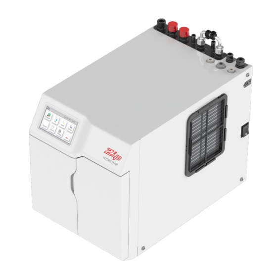
Zip HydroTap G4
®
Filtered boiling, chilled and sparkling drinking water for residential kitchens.
Chilled sparkling model
Boiling, chilled sparkling model
Command-Centre
.
TM
Command-Centre
.
TM
Affix model number label
here
802005UK
802005UK - Residential (Boiling),chilled and sparkling installation instructions - Aug 2015 - v2.01
Page 1 of 40
Advertisement
Table of Contents

Related Manuals for Zip HydroTap G4 Boiling, chilled sparkling Command-Centre


Summary of Contents for Zip HydroTap G4 Boiling, chilled sparkling Command-Centre
- Page 1 Installation instructions Zip HydroTap G4 ® Filtered boiling, chilled and sparkling drinking water for residential kitchens. Chilled sparkling model Boiling, chilled sparkling model Command-Centre Command-Centre Affix model number label here 802005UK 802005UK - Residential (Boiling),chilled and sparkling installation instructions - Aug 2015 - v2.01...
- Page 2 Tap options The G4 series offers a range of interchangeable taps to suit the customer's needs Classic HydroTap G4 range ® These standalone taps are directly compatible with the G4 Command-Centre Arc / Cube range Elite range The mixer tap range may be used in conjunction with any of the above to provide mixed hot and cold water for sanitary use.
-
Page 3: Table Of Contents
Index HydroTap G4 specifications ® Installation check list ........................4 General product features ......................5 Important safety instructions ......................6 Warnings ............................7 Major components and accessories ..................... 8 Technical specification ......................... 9 Before installation and site requirements ..................10 Installation instructions Step 1 - Measure and cut all the tap holes before fitting the taps. -
Page 4: Installation Checklist
Installation checklist Before installation • Read the instructions and check if there is adequate space to mount all of the components. Note Not all fittings are supplied with the appliance kit. Isolation valves are not supplied. • • Check the mains water pressure is within min / max requirements (see page 9). •... -
Page 5: General Product Features
General product features Thank you for purchasing a Zip HydroTap G4. Please read and follow these instructions carefully to ensure ® safe and trouble free operation. If help and advice is required, please call 0845 6 005 005 or 0345 6 005 005. -
Page 6: Important Safety Instructions
Important safety instructions This manual contains important safety and installation instructions for the Zip HydroTap ® Please read all warnings, installation requirements and installation instructions before installing any Zip HydroTap G4. This system must be installed in accordance with water supply byelaws, ®... -
Page 7: Warnings
• All installation and service work must be completed by trained and suitably qualified tradespeople. Faulty operation due to unqualified persons working on this product, or any other Zip product may void warranty coverage. • As the installer, it is your responsibility to supply (if necessary) and install all valves as required by local regulations and relevant standards. -
Page 8: Major Components And Accessories
For Zip HydroTap 160/125 &160/175 models, a 220-240Vac, 10A GPO will be BCH240/175G4 required. For Zip HydroTap 240/175 models, two 220-240Vac, 10A GPOs will be SPIDER required. (One GPO is for the Zip HydroTap and the other for the Booster heater). CLAMP NOTE: feed each of the three tubes and AV160/125G4... -
Page 9: Technical Specification
Technical specifications Chilled and sparkling HydroTap G4 range ® HydroTap ® Chilled, sparkling and filtered. Elite Classic Arc / Cube Boiling Chilled and sparkling HydroTap G4 range ® HydroTap ® Boiling, chilled, sparkling and filtered. Elite Classic Arc / Cube Mixer taps Boiling, chilled, sparkling and filtered together with mixed hot &... -
Page 10: Before Installation And Site Requirements
9 for dimensions. Make allowance for a booster if required. See sections 3 to 4, pages 22 to 27 for installation instructions. For Zip HydroTap G4 boiling, chilled and sparkling models, 1 x 220-240V AC • ®... -
Page 11: Installation Instructions
Position the tap such that it dispenses into the sink bowl with ample clearance for a cup or tea pot. Alternatively, the tap could be mounted away from the sink using a Zip Font , available as an accessory.(see Major components and accessories, page 8). -
Page 12: Hydrotap
HydroTap G4 - Tap installation ® (See page 29,30,33 for Command-Centre connections). All thread rod Clearance envelope Black plastic spacer Stainless steel spacer Spider clamp Apply a light smearing of silicon sealant on the underside of the spacer to ensure a watertight fit. -
Page 13: Installation Instructions
Installation instructions Stainless steel Black washer Fit the plastic spacer stainless steel Spider clamp washer, spider clamp, and nut. 35mm hole Ø Note Feed each of the three tubes and USB cable evenly in between the legs of the spider Pass all the hoses, tubes and USB clamp during installation. -
Page 14: Hydrotap
HydroTap G4 Arc & Cube - tap installation ® The HydroTap Arc/Cube has a spout that may be fixed in one of 6 angular positions (depending on the position of the rotary control) and fixed in one of two height positions. The spout is fixed and does not swivel. To reduce the risk of scalding, Position *A should not be selected with any of the boiling water units. -
Page 15: Installation Instructions
Installation instructions 1.7 Height adjustment (fixed position options) 50mm 1.8 Angular adjustment (fixed position options) Right hand control Left hand control 1.9 Mounting (See hole positioning, page 11 ) Upper o-ring Base Ring Cut a 35mm hole in the work / sink top. Ø... -
Page 16: Mixer Tap Installation
Mixer tap installation (See page 30 for Command-Centre connections). 1.10 Upper rubber washer Braided Lower rubber hose x 3 washer Clearance envelope Washer 1.11 Cut a 35mm hole in the worktop / sink. Ø Ø35mm Upper rubber washer Note Make sure the tap location will allow the tap spout to drain into the sink. -
Page 17: All-In-One Tap 'Mains' Installation
All-in-One tap 'Mains' installation (see page 31 for Command-Centre connections). 1.12 Clearance O-ring envelope Base block spider USB cable Base block nut 1.13 Cut a 50mm hole in the worktop / sink. Ø Ø50mm Note Make sure the tap location will allow the tap spout to drain into the sink. - Page 18 Installation instructions (see page 31 for Command-Centre connections) 1.14 Base block spider markings and silicone tube positions (viewed from underneath). Blue marking Red marking Braided hose with Braided hose with blue marking red marking Red silicone tube Blue silicone tube USB cable Clear silicone tube Installing the All-in-One 'Mains' tap...
-
Page 19: All-In-One Tap 'Vented' Installation
All-in-One tap 'Vented' installation (see page 32 for Command-Centre connections) 1.16 Clearance O-ring envelope Base block spider USB cable Base block nut 1.17 Cut a 50mm hole in the worktop / sink. Ø Ø50mm Note make sure the tap location will allow the tap spout to drain into the sink. - Page 20 Installation instructions 1.18 Base block spider markings and silicone tube positions (viewed from underneath). White marking Blue marking Braided hose with Braided hose with white marking blue marking Braided hose with red marking Red silicone tube Blue silicone tube USB cable Clear silicone tube Installing the All-in-One ‘Vented’...
-
Page 21: Section 2 - Ventilation
Section 2 Ventilation 2.1 Ventilation for all models • The clearance envelope dimensions stated in the specification sheets and installation instructions must be observed. • Adequate ventilation must be provided to ensure that the cupboard space temperature does not exceed 2.2 Preferred arrangement 4mm door buffers (at the four corners of each door) supplied with the Command-Centre should be used to... -
Page 22: Product Details And Installation Procedure
Booster system 3.1 Product description The booster system is a compact electronically controlled auxiliary water heater. It is intended to provide pre-heating of water before it enters the Zip HydroTap G4 boiling tank. The booster is supplied ® as standard with ‘vented’ All-in-One and mixer tap models. -
Page 23: Section 3 - Booster Installation
Booster installation 3.2 Installation procedure Site requirements • Booster must only be installed in a frost-free area. Never expose booster to frost. • The booster is designed for wall mounted installation and must be installed with water connectors facing upwards. •... - Page 24 Note 1 This appliance is intended for use with the Zip HydroTap G4 Command-Centre ® Note 2 Water connections must be pointing vertically upwards. Note 3 The booster unit should be installed as close as possible to the Zip HydroTap G4 as the 500mm ® connection hoses cannot be lengthened.
-
Page 25: Mount The External Filter / Softener (If Required) 3.5 Mounting The Filter Head And Cartridge Installation
Filter / softener installation An external filter / softener may be fitted to reduce the incidence of scale build up in the hot tank or may be supplied at the customer’s request. (Scale filter head fitting kit order code ZT200G4 ). 3.5 Mounting the filter head •... -
Page 26: Cylinder
Section 4 Cylinder STORAGE WARNING WARNING! The cylinder ( containing 1kg of CO ) should be installed in a well ventilated area of area no less than 38m If more than 1 gas cylinder containing 1kg of CO is present within the same location, the recommended ventilation area should be in proportion to the number of gas cylinders stored in that location. - Page 27 Regulator ON - OFF knob. Green indicator. Note When removing hose, take care not to lose plastic olive from the fitting. Leak Test After replacing a cylinder or after making a gas connection, perform a leak test Stage 1 1. Turn the gas off. 2.
-
Page 28: Section 5 - Command-Centre
Section 5 Command-Centre installation 5.1 External bypass valve The diverter bypass valve allows the user to choose to have the boiling feed water bypass the internal filter and only be filtered by the external filtration. This diverter valve is located at the rear panel of the Command-Centre , see the diagram below. -
Page 29: Boiling, Chilled And Sparkling Hydrotap ® G4 Models
Installation instructions 5.3 Boiling, chilled and sparkling Hydrotap G4 models ® (for Arc / Cube, also refer to the tube kit assembly instructions supplied with the tap head). Elite Classic Arc / Cube MAINS MIXER MIXER BOILING BYPASS VENT BYPASS POWER CABLE CHILLED... -
Page 30: Boiling, Chilled And Sparkling Hydrotap ® G4 And Mixer Tap Combinations
Installation instructions 5.4 Boiling, chilled and sparkling Hydrotap G4 and mixer tap combinations ® (for Arc / Cube, also refer to the tube kit assembly instructions supplied with the tap head). Elite Classic Arc / Cube Classic Cube Booster HydroTap Connections Mixer Connections... -
Page 31: Boiling, Chilled And Sparkling All-In-One 'Mains' Tap
Installation instructions 5.5 All-in-One 'Mains' tap MAINS MIXER MIXER BOILING BYPASS VENT BYPASS POWER CABLE CHILLED SPARKLING Note Mains hose length is 750mm. Electrical power cable length is 1800mm. Position the Command-Centre according to the hose and cable lengths supplied. (Supplied) Note All plastic / silicon tubes must be trimmed to size. -
Page 32: Boiling, Chilled And Sparkling All-In-One 'Vented' Tap
Installation instructions 5.6 All-in-One 'Vented' tap Booster Connections HydroTap Mixer Connections MAINS MIXER MIXER BOILING BYPASS VENT BYPASS POWER CABLE CHILLED SPARKLING Note Mains hose length is 750mm. Electrical power cable length is 1800mm. Position the Command-Centre according to the hose and cable lengths supplied. -
Page 33: Chilled And Sparkling Hydrotap ® G4 Models
Installation instructions 5.7 Chilled and sparkling Hydrotap G4 models (for Arc / Cube, also refer to the tube kit assembly ® instructions supplied with the tap head). Elite Classic Arc / Cube Note All plastic / silicon tubes must be trimmed to size. -
Page 34: Section 6 - Commissioning
• After commissioning, the system may be customised by selecting further options in section G - Settings, of the user guide. Commissioning 6.1 Select the language Language selection screen Initial commissioning screen Zip BC Sparkling Zip BC Sparkling 6.2 - CO purge • Press the [MENU] button for main menu. -
Page 35: Boiling Calibration
Commissioning • Press [START] / [STOP] button to start and stop the filter flush. • Open the flush stop cock. • Allow at least 10 litres of water to flush through the filter. • Once the filter flush is finished, Close the stop cock then press [STOP] to end filter flush mode. -
Page 36: Safety Sensor Calibration
Commissioning 6.6 - To enable a booster, when installed Press the [MENU] button for main menu. • Press the [Install] button. • Press the [Boost] button. • In the next screen, select [YES] to enable the booster. • Before connecting the power to the booster, water •... -
Page 37: Trouble Shooting
Flow Sensor Fault Internal fault Call Zip Service Call an electrician, a plumber, or Zip on 0845 6 005 005 or 0345 6 005 005 for assistance, service, spare parts or enquiries. End of life disposal The use of this crossed out wheeled bin logo indicates that this product needs to be disposed of separately to any other household waste. - Page 38 Notes Page 38 of 40 802005UK - Residential (Boiling),chilled and sparkling installation instructions - Aug 2015 - v2.01...
-
Page 39: Warranty
Furthermore this warranty does not displace any statutory warranty, but, to the extent to which Zip is entitled to do so, the liability of Zip under any statutory warranty will be limited at Zip’s option to the replacement of the... -
Page 40: Contact Details
The terms “Zip” and “HydroTap” are registered trade marks of Zip Heaters (Aust) Pty Ltd. Zip products described in this publication are manufactured under one or more of the following patents: AU675601, AU637412, AU635979, GB0422305, GB2065848, US4354049, US5103859, US5099825 and SA2006/08043. Other patents are in force and patent applications are pending.
Need help?
Do you have a question about the HydroTap G4 Boiling, chilled sparkling Command-Centre and is the answer not in the manual?
Questions and answers